
Related Manuals for Kogan SMARTERHOME KASHSAC26TA


Summary of Contents for Kogan SMARTERHOME KASHSAC26TA
- Page 1 KOGAN SMARTERHOME™ INVERTER SPLIT SYSTEM AIR CONDITIONER (2.6KW, 3.5KW & 7.0KW) (REVERSE CYCLE) KASHSAC26TA, KASHSAC35TA & KASHSAC70TA...
-
Page 2: Table Of Contents
Safety & Warnings Overview Installation Connect to SmarterHome™ App Google Home Control Amazon Alexa Control Operation Cleaning & Care Troubleshooting Notes... -
Page 3: Safety & Warnings
SAFETY & WARNINGS • Read this guide before installing and using the appliance. • During the installation of the indoor and outdoor units, access to the working area should be forbidden to children. Unforeseeable accidents could happen. • Ensure that the base of the outdoor unit is firmly secured. •... - Page 4 • The appliance must be installed in accordance with national wiring regulations. • This appliance can be used by children aged from 8 years and above and persons with reduced physical, sensory or mental capabilities or lack of experience and knowledge if they have been given supervision or instruction concerning use of the appliance in a safe way and understand the hazards involved.
- Page 5 • Do not bend, tug, or compress the power cord, as this could cause damage. A damaged power cord can lead to electrical shocks or fire. The power cord must only be replaced by a qualified trade professional should replace the power cord. •...
-
Page 6: Overview
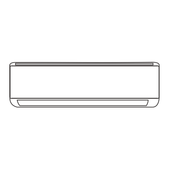
OVERVIEW Indoor Unit Mounting plate Front panel Emergency button Air filter Air outlet Air deflector and flap Refrigerant connecting pipe Outdoor Unit (With the Protective Cover Removed) Air inlet Wiring cover Air outlet Drainage pipe Connection wiring Valve protective cover Gas valve (low pressure valve) Liquid valve (high... - Page 7 Indoor Display Icon Function Time display. This is the indicator for the timer, temperature and error codes. Timer indicator. Sleep mode indicator. This indicator illuminates when the appliance is turned on and disappears when the appliance is turned off. Power indicator. The symbol illuminates when the power is on. Note: The shape and position of buttons and indicators may be different according to the model, but their function is the same.
- Page 8 Remote control display: Symbol Meaning Battery indicator Auto mode Cool mode Dry mode Fan only mode Heat mode Eco mode Timer Temperature indicator Fan speed: Auto/ low/ low-mid/ mid/ mid- high/ high Mute function Turbo function Up-down auto swing Left-right auto swing Sleep function Health function I Feel function...
- Page 9 Remote control buttons: Button Function Turn the air conditioner on/off. Press to increase the temperature or Timer setting hours. Press to decrease the temperature or Timer setting hours. MODE Press to select the mode of operation (Auto, Cool, Dry, Fan, Heat). Press to activate/deactivate the ECO function.
-
Page 10: Installation
INSTALLATION Important Considerations • The air conditioner must be installed by a licensed trade professional. • When filling the combustible refrigerant, incorrect operation may cause serious injury or damage to the appliance. • A leak test must be done after installation is completed. •... - Page 11 Table GG.2 – Minimum Room Area (m Charge amount (M) (kg) Category (kg/m Minimum room area (m 1.224 1.386 2.448 3.672 4.896 6.12 7.956 0.306 Installation Safety Principles Site safety: Open flames prohibited Ventilation necessary Operation safety: Mind static Must wear protective clothing and anti- Don`t use mobile electricity static gloves...
- Page 12 15 minutes. If the product is damaged, cease use immediately and contact help.Kogan.com for support. Welding the refrigerant pipe or performing other operations on-site is strictly prohibited.
- Page 13 Suggested Tools Tool Picture Tool Picture Tool Picture Standard Vacuum Pipe cutter spanner pump Screw drivers Adjustable/ Safety crescent (Phillips glasses wrench head & flat head) Manifold Torque Work wrench gloves gauges Refrigerant Allen key Level scale Drill & drill Micron Flaring tool bits...
- Page 14 Pipe Length and Additional Refrigerant Inverter models 9K-12K 18K-24K 30K-36K capacity (Btu/h) Length of pipe with standard charge 16ft 16ft 16ft 16ft 16ft 16ft Length of pipe with 7.5m/ 7.5m/ 7.5m/ 7.5m/ 7.5m/ 7.5m/ standard charge (Like: 24ft 24ft 24ft 24ft 24ft 24ft...
- Page 15 Torque Parameters Newton meter (N x Pound-force foot Kilogram-force Pipe size (lbs-ft) meter (kgs-m) 1/4 (∅6.35) 15-20 11.1 – 14.8 1.5-2.0 3/8 (∅9.52) 31-35 22.9-25.8 3.2-3.6 1/2 (∅12) 45-50 33.2-36.9 4.6-5.1 5/8 (∅15.88) 60-65 44.3-48.0 6.1-6.6 Dedicated Distribution Device and Wire for Air Conditioner Min.
- Page 16 • The indoor unit is out of reach of children. • A mounting wall strong enough to withstand four times the full weight and vibration of the unit. • The filter can be easily accessed for cleaning. • Leave enough free space to allow access for routine maintenance. •...
- Page 17 Step 2: Install the Mounting Plate Take the mounting plate from the back of the indoor unit. Ensure you meet the minimum installation dimension requirements as described in step 1. Based on the size of the mounting plate, determine the position and stick the mounting plate close to the wall.
- Page 18 Step 3: Drill the Wall Hole A hole in the wall should be drilled for refrigerant piping, the drainage pipe and connecting cables. Determine the location of the wall hole based on the position of the mounting plate. The hole should have a diameter of at least 70mm and a slight oblique angle to facilitate drainage.
- Page 19 Step 4: Connecting the Refrigerant Pipe Based on the wall hole position, select the appropriate piping mode. There are three optional piping modes for indoor units, as shown in the figure below. In Piping Mode 1 or Piping Mode 3, a notch should be made by using scissors to cut the plastic sheet of the piping outlet and cable outlet on the corresponding side of the indoor unit.
- Page 20 Wrap the joint with the insulation pipe. Note: For R32 refrigerant, the connector should be placed outdoors. Indoor Outdoor The connector should be outdoor Step 5: Connect Drainage Hose Adjust the drainage hose (if applicable). In some models, both sides of the indoor unit are provided with drainage ports.
- Page 21 Wrap the joint firmly with Teflon tape to ensure no leaks. Note: Ensure the pipes are free from twists or dents and are positioned with a downward slope to prevent blockages and ensure proper drainage. Step 6: Connect Wiring Choose the appropriate cable size based on the maximum operating current indicated on the nameplate (refer to the Installation Precautions section).
- Page 22 Step 7: Wrap Piping and Cable After the refrigerant pipes, connecting wires, and drainage hose are all installed, they must be bundled with insulating tape before passing them through the wall hole. This will save space, protect, and insulate them. Arrange the pipes, cables, and drainage hose as shown in the following figure.
- Page 23 If the refrigerant pipes were already embedded in the wall or if you want to connect the pipes and wires on the wall, follow these steps: Hook the top of the indoor unit onto the mounting plate without piping and wiring. Lift the indoor unit away from the wall, unfold the bracket on the mounting plate, and use this bracket to prop up the indoor unit, creating a larger space for operation.
- Page 24 Step 2: Install Drainage Hose This step only for heat pump models or RCACs. Insert the drainage joint to the hole at the bottom of the outdoor unit. Connect the drainage hose to the joint and make the connection well enough. Drainage joint Drainage hose Step 3: Fix Outdoor Unit...
- Page 25 Step 4: Install Wiring Use a Phillips head screwdriver to unscrew the wiring cover, then gently grasp and press it down to remove it. Unscrew the cable clamp and remove it. According to the wiring diagram inside the wiring cover, connect the wires to the corresponding terminals and ensure all connections are firm and secure.
- Page 26 Step 5: Connect the Refrigerant Pipe Unscrew the valve cover, then gently grasp and press it down to remove it (if applicable). Remove the protective caps from the ends of the valves. Remove the plastic cover from the pipe ports, check for any debris on the port of the connecting pipe, and ensure the port is clean.
- Page 27 Step 6: Vacuum Pumping Use a spanner to remove the protective caps from the service port, low-pressure valve, and high-pressure valve of the outdoor unit. Connect the pressure hose of the manifold gauge to the service port on the outdoor unit's low-pressure valve. Connect the charge hose from the manifold gauge to the vacuum pump.
- Page 28 Replacing the Remote Control Batteries Remove the battery cover plate from the back of the remote control by sliding it in the direction indicated by the arrow. Install the batteries according to the ‘+’ and ‘-’ directions shown on the remote control.
- Page 29 DIP Switch For some remote control models, open the battery cover to reveal a manual switch at the bottom. You can then select either the Cooling Only or Heat Pump mode. Position the switch according to the table below. DIP Switch Position Function °C The display is adjusted in Celsius.
-
Page 30: Connect To Smarterhome™ App
CONNECT TO SMARTERHOME™ APP Install App Download the “Kogan SmarterHome” app from the Play Store (Android) or App Store (iOS). Play Store (Android) App Store (iOS) To register: If you already have a SmarterHome account, select ‘Log In’. To register a new account, select ‘Sign Up’. - Page 31 Add device through network Once registered, power on the indoor unit, no need to launch the air conditioner. Tap the “+” in the upper right corner, press "Scan", and then scan below QR code. Click “Add”. Enter your Wi-Fi details. It is important that your SmarterHome™...
- Page 32 Follow the in-app prompts to continue AP Mode connection, which will pair your mobile phone to the device’s Wi-Fi hotspot to ensure a connection. This may be named ‘SL-KoganSmart”, “SmartLife-XXXX’, or another similar name. Note: If the Wi-Fi hotspot does not appear on your phone in the list of available networks, your device may not be set in AP Pairing Mode correctly.
-
Page 33: Google Home Control
GOOGLE HOME CONTROL Note: You will need to have set up a Google Home account prior to linking your Kogan SmarterHome™ device. Adding “SmarterHome” to the Google Home app From the home page of the Google Home app, select the “+” icon (top left corner, see arrow in the below screenshot) to access the ‘Add and manage’... - Page 34 Select the search bar and type ‘Smarter Home’ to locate the Kogan SmarterHome™ service. From here, you will be prompted to sign into your SmarterHome™ account using either your email or mobile phone number, depending on which method you used to register your account.
- Page 35 Tap on any of the devices to view a list of available commands. Note: Please note that Google Home can only control the base/core functions of any compatible SmarterHome™ devices. To make full use of this product’s smart functionality, please use the Kogan SmarterHome™ app.
-
Page 36: Amazon Alexa Control
AMAZON ALEXA CONTROL Note: You will need to have set up an Alexa account prior to linking your Kogan SmarterHome™ device. Adding “SmarterHome” to the Alexa app From the home page of the Alexa app, select the “ ” icon in the bottom-right and select “Skills &... - Page 37 Tap ‘Enable to Use’ to add the Kogan SmarterHome™ skill to Alexa. From here, you will be prompted to sign into your SmarterHome™ account using either your email or mobile phone number, depending on which method you used to register your account.
- Page 38 Once connected, the app will perform a search and display the devices linked to your SmarterHome™ account. When your devices have successfully connected to the Alexa app, you will be able to control your Kogan SmarterHome™ devices via Alexa’s voice commands.
-
Page 39: Operation
OPERATION Cooling Mode • The cooling function allows the air conditioner to cool the room and reduce air humidity at the same time. • To activate the cooling function (COOL), press the ‘MODE’ button until the Cool mode indicator appears on the display. •... - Page 40 Heating Mode • The heating function allows the air conditioner to heat the room. • To activate HEAT mode, press the ‘MODE’ button until the Heat mode indicator appears on the display. • Press the button to set a temperature higher than that of the room. •...
- Page 41 Timer Function ---- Timer On • Automatically switch on the appliance. • When the unit is switched off, you can set the TIMER ON. To set the time for automatic switch-on, follow these steps: Press the ‘TIMER’ button to set the switch-on time. The Timer and Temperature indicators will flash on the remote control display.
- Page 42 Swing Function • Press the button SWING to activate the air deflectors: Press ‘SWING’ to activate the horizontal deflectors to swing up and down. The Up- down auto swing indicator will appear on the remote display. Press again to stop the swing movement at the current angle.
- Page 43 Sleep Function • Pre-set the automatic operating program. • Press the ‘SLEEP’ button to activate the SLEEP function. The Sleep function indicator appears on the display. Press again to cancel this function. • After 10 hours running in SLEEP mode, the air conditioner will change to the previously set mode.
- Page 44 Self-Clean Function • To active this function, turn off the indoor unit, then press both ‘SWING’ buttons at the same time while pointing towards the indoor unit until you hear a beep. ‘AC’ will appear on the remote control display and the indoor LED display. •...
- Page 45 Inverter air conditioner: MODE Heating Cooling Temperature Room temperature 0°C~27°C (32°F~80°F) 17°C~32°C (63°F~90°F) T1 climate: 15°C~50°C (59°F -15°C~24°C (5°F~75°F) ~122°F) (Low temperature cooling: Outdoor (Low temperature -15°C ~50°C (5°F~122°F)) temperature heating: -20°C~24°C T3 climate: 15°C~55°C (-4°F~75°F)) (59°F~131°F) With the power supply connected, restart the air conditioner after shutdown or switch it to another mode during operation and the air conditioner protection device will start.
- Page 46 Emergency button: Open the panel and find the emergency button on the electronic control box when the remote control fails. Always press the emergency button with insulation material. Status Operation Respond Enter mode Press the It beeps briefly Standby. emergency button Cooling mode.
- Page 47 • Ensure ventilation openings clear of obstruction. • Notice: Servicing shall be performed only as recommended by Kogan.com. • Warning: The appliance shall be stored in a well-ventilated area where the room size corresponds to the room area as specified for operation.
- Page 48 Warning • Do not use any means to accelerate the defrosting process or clean the frost on your own. Follow the recommended guidelines from Kogan.com. • The appliance shall be stored in a room without continuously operating ignition sources (for example: open flames, an operating gas appliance or an operating electric heater).
- Page 49 At all times, the maintenance and service guidelines shall be followed. • If in doubt, contact help.Kogan.com for support. • The following checks shall be applied to installations using flammable refrigerants: The charge size is in accordance with the room size within which the refrigerant containing parts are installed.
- Page 50 Checks to electrical devices: Repair and maintenance to electrical components shall include initial safety checks and component inspection procedures. If a fault exists that could compromise safety, then no electrical supply shall be connected to the circuit until it is satisfactorily dealt with. If the fault cannot be corrected immediately but it is necessary to continue operation, an adequate temporary solution shall be used.
- Page 51 Intrinsically safe components are the only types that can be worked on while live in the presence of a flammable atmosphere. The test apparatus shall be at the correct rating. Replace components only with parts specified by Kogan.com. Other parts may result in the ignition of refrigerant in the atmosphere from a leak.
- Page 52 Removal and evacuation: When breaking into the refrigerant circuit to make repairs or for any other purpose conventional procedures shall be used. However, it is important that best practice is followed since in flammability is a consideration. The following procedure shall be adhered •...
- Page 53 • Make sure that the cylinder is situated on the scales before recovery takes place. • Start the recovery machine and operate in accordance with Kogan.com’s instructions. • Do not overfill cylinders. (No more than 80 % volume liquid charge).
- Page 54 Contact help.Kogan.com if in doubt. The recovered refrigerant shall be returned to the refrigerant supplier in the correct recover cylinder and the relevant waste transfer note arranged.
- Page 55 Inspections Before Test Run Description Inspection method • Check whether the power supply voltage complies with specification. • Check whether there is any wrong or missing connection Electrical safety inspection between the power lines, signal line and earth wires. • Check whether the earth resistance and insulation resistance comply with requirements.
- Page 56 Test Run Instructions T urn on the power supply. P ress the Power button on the remote control to turn on the air conditioner. P ress the MODE button to switch between COOL and HEAT modes. Set the temperatures as follows: COOL: Set to the lowest temperature.
-
Page 57: Cleaning & Care
CLEANING & CARE Warning • When cleaning, you must shut down the machine and cut off the power supply for more than 5 minutes. • Under no circumstances should the air conditioner be flushed with water. • Volatile liquid (e.g. thinner or gasoline) will damage the air conditioner, so only use soft dry cloth or wet cloth dipped with neutral detergent to clean the air conditioner. - Page 58 Clean the Filter <40°C (104°F) Clean the filter with soapy Take out the filter from the unit water and air dry it Opposite to the direction of taking out the filter. Replace the filter Note: When you find accumulated dust in the filter, clean the filter promptly to ensure the clean, healthy and efficient operation inside the air conditioner.
-
Page 59: Troubleshooting
TROUBLESHOOTING Problem Possible Causes Power failure/plug pulled out. Damaged indoor/outdoor unit fan motor. Faulty compressor thermomagnetic circuit breaker. Faulty compressor thermomagnetic circuit breaker. The appliance does Loose connections or plug pulled out. not operate. It sometimes stops operating to protect the appliance. Voltage higher or lower than the voltage range. - Page 60 Strange noises during operation. Faulty electronic control board. Switch off the air conditioner Faulty fuses or switches. immediately and cut Spraying water or objects inside the appliance. off the power supply in the event of: Overheated cables or plugs. Very strong smells coming from the appliance. Error Code on the Display In case of an error, the following error codes will illuminate on the indoor unit display.
-
Page 61: Notes
NOTES... - Page 64 Need more information? We hope that this user guide has given you the assistance needed for a simple set-up. For the most up-to-date guide for your product, as well as any additional assistance you may require, head online to help.kogan.com...
Need help?
Do you have a question about the SMARTERHOME KASHSAC26TA and is the answer not in the manual?
Questions and answers