
Related Manuals for Spectris SERVOMEX SERVOPRO HFID


Summary of Contents for Spectris SERVOMEX SERVOPRO HFID
- Page 1 SERVOPRO NOX GAS ANALYZER 221195Q Quick Start Guide PN SERVOPRO HFID Gas Analyzer 221196Q Quick Start Guide PN...
-
Page 2: Table Of Contents
TABLE OF CONTENTS INTRODUCTION ..........................4 SAFETY ............................5 DESCRIPTION ..........................6 Overview ..............................6 Features ..............................6 Heated Oven ............................. 8 Flow System .............................. 8 INSTALLATION ..........................9 Overview of Potential Hazards ......................... 9 Filter Housing Maintenance ........................10 Unpacking Instructions ........................... - Page 3 +1 281 295 5899 (US toll free) f: + 44 (0) 1892 662 253 e: europe_sales@servomex.com americas_sales@servomex.com w: www.servomex.com www.servomex.com © 2018. Servomex Group Limited. A Spectris Company. All rights reserved SERVOPRO HFID Analyzers Quick Start Guide Rev 1 Page 3...
-
Page 4: Introduction
INTRODUCTION About this Quick Start Guide This guide covers the basics of the installation, connections, software interface overview and routine maintenance of the SERVOPRO HFID. It is not intended to be a full installation manual but is a quick guide for those that are familiar with the use and maintenance of analytical or process instrumentation. -
Page 5: Safety
SAFETY Safety information Read this Quick Start Guide and the full SERVOPRO HFID Installation and Operations manual. Make sure you fully understand its contents before you attempt to install or operate the analyzer. The following icons are used throughout the manuals to identify any potential hazards that could cause serious injury to people. -
Page 6: Description
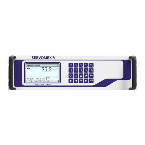
DESCRIPTION OVERVIEW The Servomex SERVOPRO HFID analyzer is an exceptionally accurate Flame Ionization Detection (FID) gas analyzer designed for measuring hydrocarbons concentrations in gaseous samples. The analyzer utilizes a highly sensitive flame ionization detector for measuring volatile hydrocarbon concentrations in industrial stationary source or mobile source (such as vehicle or engine certification) emission applications. - Page 7 • Fast response time • ETL listed – conforms to UL STD 61010-1, certified to CAN/CSA C22.2 STD 61010.1 • EPA 40 CFR Part 1065/1066 and Euro VI HD and Euro 6 LD compliant configurations The analyzer offers four basic factory ranges 30/300/3,000/30,000 (C1 as ppm or mg/m ) or 10/100/1,000/10,000 (C3 as ppm or mg/m ) which can be scaled and preset to either ppm or...
-
Page 8: Heated Oven
then the analyzer performance will be adversely affected and/or it may damage the cutter material. HEATED OVEN The heated sample gas is maintained above its dew point by a self-contained internal oven. The oven temperature is adjusted at the factory to be controlled at 191°C. The sample gas is maintained at this elevated temperature until it exits the analyzer’s bypass outlet, preventing any loss of hydrocarbon concentration in the sample due to condensation. -
Page 9: Installation
INSTALLATION OVERVIEW OF POTENTIAL HAZARDS WARNING: ALWAYS DISCONNECT THE POWER BEFORE CONNECTING OR DISCONNECTING SIGNAL CABLES OR WHEN SERVICING THE EQUIPMENT. Potential Explosion Hazard WARNING: This analyzer uses a fuel that contains a FLAMMABLE LEVEL OF HYDROGEN. Any leakage from this fuel can result in an explosion. -
Page 10: Fuel Requirements
Fuel Requirements The SERVOMEX factory configures the SERVOPRO HFID analyzer for either 100% Hydrogen or 40%/60% Hydrogen/Helium fuel. Please make sure to use the correct fuel as specified on the fuel label affixed to the back panel of the analyzer. WARNING: Use of incorrect fuel will damage the instrument and could cause an explosion. -
Page 11: Unpacking Instructions
2. Always use a second wrench on the body of the filter housing when attempting to inspect or replace the filter. 3. Always allow the filter housing to cool to room temperature before attempting any maintenance. WARNING: Never attempt to disassemble or reassemble the filter housing while it is hot. -
Page 12: Rear Panel
The front panel is designed for mounting into a standard 19-inch rack enclosure. Holes are located on the left and right side to allow the panel to be secured in the rack by screws. Optional rack slides allow the analyzer to be pulled out of the rack enclosure for access. Rear Panel The rear panel includes the following: 1) Sample Gas Bypass outlet (vent) for exhaust of sample ¼-inch (6mm) tube. -
Page 13: Electrical
2. This analyzer is not suitable for installation outdoors. 3. Select a site where the air is clean. Avoid exposing the instrument to corrosive or combustible gases. 4. Do not subject the analyzer to severe vibration. If severe vibration is present, use isolation mounts. -
Page 14: Output Connections
OUTPUT CONNECTIONS See the Analog and Digital Interface section of the Operations Manual for instructions for the various output selection options. Shielded wiring is recommended for output signals. GAS REQUIRMENTS AND HANDLING EQUIPMENT 1. Air (zero calibration gas and burner air, < 1 ppm C) in pressurized cylinder. 2. -
Page 15: Sampling Requirements
tubing should be as short as possible. Optimum tube internal diameter is 0.16 inch (4 mm). Couplings to the instrument use ¼-inch (6mm) tubing. A sample gas bypass fitting is located on the rear panel. Keep pressure at this outlet at atmospheric level. - Page 16 Pressure and Flow Rates The sample gas flow entering the instrument is regulated by an electronic proportional control (EPC) valve to ensure that constant pressure is maintained at the sample capillary. The pressure is factory set for optimal analyzer performance. The fuel and air entering the instrument are also controlled by a factory-set EPC valve.
-
Page 17: Startup And Shutdown
STARTUP AND SHUTDOWN GENERAL STARTUP INFORMATION Before using the SERVOPRO HFID, make sure the external plumbing and wiring have been connected correctly as shown in the Rear Panel description. All connections (combustion air, combustion fuel, zero gas and span gas) should be leak tight, and inlet pressure settings adjusted as previously described. -
Page 18: Storage
STORAGE After power down, allow the heated analyzer components to cool to room temperature before preparing for storage. If the original shipping box was retained, the analyzer should be stored in the box in the packing material supplied. If the original box is not available and another appropriate box cannot be obtained, the analyzer can be placed in a clean, dry plastic bag. -
Page 19: Menu Navigation Chart
MENU NAVIGATION CHART The menu flow chart is a handy reference that will help you familiarize yourself with the operation of the SERVOMEX System SERVOPRO HFID Analyzer. Start by pressing access the Main Menu to quickly find any screen. NOTE: In the diagram below all functions are available except under the Measure Mode (F2) function where the CH Mode (F2) and the THC/CH / NMHC... -
Page 20: Calibration Menu
CALIBRATION MENU SERVOPRO HFID Analyzers Quick Start Guide Rev 1 Page 20... -
Page 21: Range Menu
RANGE MENU SERVOPRO HFID Analyzers Quick Start Guide Rev 1 Page 21... -
Page 22: Diagnostics Menu
DIAGNOSTICS MENU SERVOPRO HFID Analyzers Quick Start Guide Rev 1 Page 22... -
Page 23: Setup Menu
SETUP MENU SERVOPRO HFID Analyzers Quick Start Guide Rev 1 Page 23... -
Page 24: Alarms Menu
ALARMS MENU SERVOPRO HFID Analyzers Quick Start Guide Rev 1 Page 24... -
Page 25: Service Menu
SERVICE MENU SERVOPRO HFID Analyzers Quick Start Guide Rev 1 Page 25... -
Page 26: Security Menu
SECURITY MENU SERVOPRO HFID Analyzers Quick Start Guide Rev 1 Page 26... -
Page 27: Using The Main Menu
USING THE MAIN MENU USING THE KEYPAD When the Measure screen is displayed, the ten Function keys (F1 through F10) are shortcuts to commonly used screens. On other screens, these keys can either be used as function keys or to enter numeric values. -
Page 28: Main Menu Screen
The Enter key: 1. In Function mode (F), the Enter key selects the highlighted function. 2. In Numeric mode (N), when a field is highlighted for numeric input, pressing the Enter key opens the selected field for numeric entry with a blinking cursor. Pressing the Enter key a second time exits the Numeric Entry field. -
Page 29: Shortcut Menu
All software functions of the SERVOPRO HFID analyzer can be reached via the menu above from the Main Menu screen. Operation starts by pressing the Menu key to bring up the Main Menu. Use the Arrow keys to highlight the desired function and press to open the screen. -
Page 30: Measure Screen
Operators can change Span gas concentrations for multiple Span Conc ranges. Allows operators to set or adjust the CH Correction Factors Factors if using the NMHC Model analyzer. MEASURE SCREEN in Function Mode (F) NOTE The Measure Screen provides a visual of the current concentration of the gas being analyzed, along with other pertinent information. -
Page 31: Measure Mode
Please review the following descriptions (corresponding with the callouts on the illustration above) to familiarize yourself with the Measure Screen. Diagram Above Description Call Outs Screen Name The name of the active screen the Analyzer is in; in this case the Measure screen. - Page 32 NOTE The Measure Mode menu is used to select one of three measurement modes: THC, CH or THC/CH /NMHC if using the NMHC Model analyzers otherwise only the THC Mode is allowed. The Measure Mode menu is accessed by pressing the key on the Main Menu.
- Page 33 → → To change to the CH mode, press while in the Measure Mode menu. In CH mode, the sample gas passes through the non-methane cutter and the analyzer measures Methane. THC/CH /NMHC MODE (NMHC MODEL ONLY) → → NOTE The THC/CH /NMHC ode activates the “sample and hold”...
-
Page 34: Analyzer Info
To change to the THC/CH /NMHC mode, press from the Measure Mode menu. The current measuring mode (cycle) is indicated above the analyzer range on the right hand side of the display (Example above: CH The cycle times of the sample read are set on the THC/CH /NMHC Mode Times screen. -
Page 35: Remote/Manual
This screen includes the Model and Serial Number of your analyzer (for easy identification if you are discussing your analyzer with SERVOMEX), factory settings for Sample pressure, Fuel pressure and Air pressure, and the software versions being used. The analyzer’s current IP address appears in the upper-right corner of the screen. -
Page 36: Standby
STANDBY → → NOTE When the analyzer is in Standby Mode, the pump is turned off and the solenoid valves are closed. The SERVOMEX logo is displayed along with the Serial Number. Standby mode is accessed by pressing the key from the Main Menu. IGNITION →... - Page 37 At the start of the ignition sequence the fuel valve will open five seconds before the air valve to prime the burner. The analyzer will try to ignite up to five times (280 seconds). Once the flame temperature reaches above 250° C, the analyzer is lit and will return to the Main Menu. Notes: •...
-
Page 38: Warranty
WARRANTY Servomex instruments are warranted to be free from defects in workmanship and materials. Liability under this warranty is limited to servicing, calibrating, and replacing any defective parts of the instrument returned to an authorized Servomex Service Center for that purpose. Fuses are specifically excluded from any liability. -
Page 39: Maintenance Policy
IMPLIED, BEYOND THOSE SET FORTH HEREIN, and the Seller does not assume any other obligation or liability in connection with the sale or use of said products. MAINTENANCE POLICY In cases when equipment fault is suspected, please notify your representative of the problem and provide them with model and serial numbers.
Need help?
Do you have a question about the SERVOMEX SERVOPRO HFID and is the answer not in the manual?
Questions and answers