
Related Manuals for Spectris PARTICLE MEASURING SYSTEMS AirSentry II


Summary of Contents for Spectris PARTICLE MEASURING SYSTEMS AirSentry II
- Page 1 Without measurement there is no control AirSentry® II Mobile AMC System OPERAT I ON S M A N UA L P/N 1000015778...
- Page 2 AirSentry® II Mobile AMC System Operations Manual HEADQUARTERS BRAZIL JAPAN SINGAPORE 5475 Airport Blvd +55 11 5188 8227 +81 3 5298 8175 +65 6496 0330 Boulder, Colorado 80301 USA pmsbrazil@pmeasuring.com pmsjapan@pmeasuring.com pmssingapore@pmeasuring.com +1 303 443 7100, +1 800 238 1801 CHINA KOREA SWITZERLAND...
- Page 3 AirSentry® II Mobile AMC System Operations Manual Part Number (P/N) 1000015778 Rev G © 2020 by Particle Measuring Systems, Inc. All rights reserved. AirSentry® is a registered trademark of Particle Measuring Systems, Inc. Swagelok® is a registered trademark of Swagelok Company. All trademarks appearing in this manual are the property of their respective owners.
- Page 4 Manual Conventions This manual uses the following conventions that call the reader’s attention to certain text WARNING A warning in the text is used to notify the user of the potential for bodily injury or death. CAUTION A caution in the text is used to highlight an item that if not done, or incorrectly done, could damage the instrument and/or any materials or devices affected by the instrument.
- Page 5 CE – Declaration of Conformity - Declaration of Conformity Application of Council Directive(s): 2014/30/EU, 2014/35/EU, RoHS 2011/65/EU Standard(s) to which Conformity is Declared: EN 61326-1:2013 Safety EN 61010-1:2010, 3rd Ed. Weltall Technology Corp. Manufacturer’s Name: Manufacturer’s Address: No. 7, Lane 82, Gongyuan Rd., East District, Hsin-Chu 300, Taiwan (R.O.C.) Manufacturer’s Telephone/FAX: +866-3-5610528 / +866-3-5619183...
- Page 6 General Safety Instructions • Maintain the machine in a clean and orderly condition to ensure proper and safe operation. • Disconnect the AMC cart from the AC power source, and power-down all CDA air Systems (compressor), and UPS, before carrying out any maintenance, calibration or repair procedures.
- Page 7 This page is intentionally left blank. AirSentry® II Mobile AMC System Operations Manual...
-
Page 8: Table Of Contents
Table of Contents Chapter 1: Introduction - - - - - - - - - - - - - - - - - - - - - - - - - - - - - - - - - - - - - - - - - - - - - 1-1 System Components- - - - - - - - - - - - - - - - - - - - - - - - - - - - - - - - - - - - - - - 1-3 Diagrams - - - - - - - - - - - - - - - - - - - - - - - - - - - - - - - - - - - - - - - - - - - - - - - - 1-4 Pneumatic Diagram - - - - - - - - - - - - - - - - - - - - - - - - - - - - - - - - - - - - - - 1-4... - Page 9 General System Overview- - - - - - - - - - - - - - - - - - - - - - - - - - - - - - - - - - - A-2 Monitor Shelf - - - - - - - - - - - - - - - - - - - - - - - - - - - - - - - - - - - - - - - - - - - - A-3 CDA, Vacuum, Sample Tees, and 24 VAC Connectors- - - - - - - - - - - - - - A-3 Pneumatic Enclosure - - - - - - - - - - - - - - - - - - - - - - - - - - - - - - - - - - - - - - A-4 UPS Controls - - - - - - - - - - - - - - - - - - - - - - - - - - - - - - - - - - - - - - - - - - - - - A-5...
- Page 10 List of Figures Chapter 1: Introduction - - - - - - - - - - - - - - - - - - - - - - - - - - - - - - - - - - - - - - - - - - - - - - - - - - - 1-1 Figure 1-1 AirSentry II Mobile AMC System - - - - - - - - - - - - - - - - - - - - - - - - - - - - - - - - - - - - - - - - - - - - 1-2 Figure 1-2 Pneumatic diagram - - - - - - - - - - - - - - - - - - - - - - - - - - - - - - - - - - - - - - - - - - - - - - - - - - - - - 1-4 Figure 1-3 Electrical diagram - - - - - - - - - - - - - - - - - - - - - - - - - - - - - - - - - - - - - - - - - - - - - - - - - - - - - - 1-5...
- Page 11 Figure 5-20 Exposed wires (left), female spade plugs (right) - - - - - - - - - - - - - - - - - - - - - - - - - - - - - - 5-16 Figure 5-21 Compressor replacement components - - - - - - - - - - - - - - - - - - - - - - - - - - - - - - - - - - - - - 5-17 Figure 5-22 Bolts on top of pump for dual chamber compressor - - - - - - - - - - - - - - - - - - - - - - - - - - 5-17 Figure 5-23 Bottom of middle plate, red gasket and reeds - - - - - - - - - - - - - - - - - - - - - - - - - - - - - - - 5-18...
-
Page 12: Chapter 1: Introduction
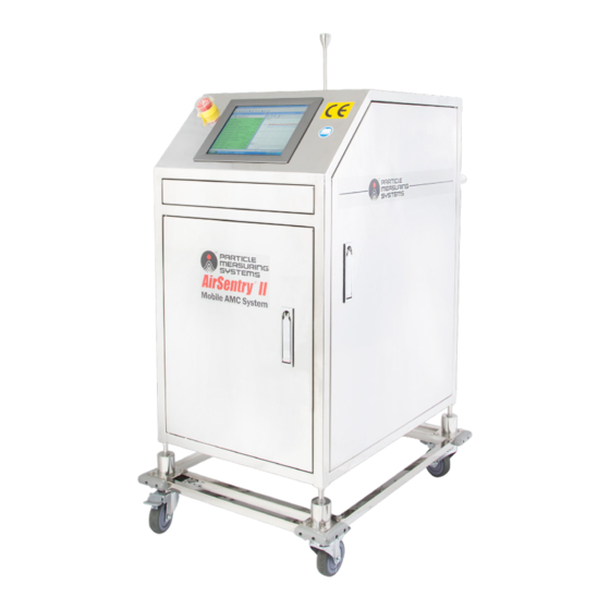
Chapter 1 Introduction The AirSentry II Mobile AMC System is the first truly mobile system for monitoring airborne molecular contamination (AMC) in cleanroom environments and within process equipment. Mobility plays an important part within a strategic AMC monitoring program, allowing potential contamination sources to be quickly and precisely located and quantified, regardless of location. -
Page 13: Chapter 1: Introduction
Chapter 1 : Introduction Figure 1-1 AirSentry II Mobile AMC System AirSentry® II Mobile AMC System Operations Manual... -
Page 14: System Components
System Components Chapter 1 : Introduction System Components The following items are included in the Mobile AMC System: Table 1-1 System Components Item Description Local Touch PC Display With Facility Net software, AirSentry II Service Software, and UPS Management Software Uninterruptable Power Supply Supplies over 30 minutes of power when disconnected from external power source... -
Page 15: Diagrams
Chapter 1 : Introduction Diagrams Diagrams Pneumatic Diagram Figure 1-2 Pneumatic diagram • The first CDA pressure regulator should always be set to 15 psig. • The second CDA pressure regulator should always be set at 5 psig (34.5 kPa). •... -
Page 16: Electrical Diagram
Diagrams Chapter 1 : Introduction Electrical Diagram Figure 1-3 Electrical diagram • Power-in based on ordered configuration: • 110 VAC 60Hz –OR– 230 VAC 50 Hz • Not universal voltage AirSentry® II Mobile AMC System Operations Manual... -
Page 17: Specifications
Chapter 1 : Introduction Specifications Specifications Table 1-2 Specifications CDA quality < -60 °C dew point, chemically filtered CDA capacity > 800 cc/min for < 30 minutes Working time (fully-charged/ 30 minutes, under optimal conditions pressurized Bypass CDA inlet (low vibration 1/4-inch Swagelok®... -
Page 18: Chapter 2: Installation Instructions
Chapter 2 Installation Instructions NOTE: Please refer to Appendix A for reference pictures. The AirSentry II Mobile AMC System cart is delivered with the following items already installed inside: • Uninterruptable power supply • DC Power supply and distribution • Vacuum system •... -
Page 19: Chapter 2: Installation Instructions
Chapter 2 : Installation Instructions To complete the set-up of the AirSentry II Mobile AMC System, follow the instructions listed below. 1. Install provided ULPA filter at bottom of cart. 2. Install the AirSentry II Analyzer(s) - Place up to 3 sensors in the rack. Using the 1/4-inch PFA tubing provided connect the following pneumatic connections. -
Page 20: Chapter 3: Uninterruptable Power Supply (Ups) Monitor Software
Chapter 3 Uninterruptable Power Supply (UPS) Monitor Software UPS Software UPSMON (UPS monitoring software) allows the user to view several settings and performance values of the UPS system. Figure 3-1 UPSMON Main GUI (Connect Button settings shown) The UPSMON main screen interface is divided into 3 areas (see Figure 3-1): 1. -
Page 21: Chapter 3: Uninterruptable Power Supply (Ups) Monitor Software
Chapter 3 : Uninterruptable Power Supply (UPS) Monitor Software UPS Software • Historical Event - Displays table of event times and descriptions. • Record Viewer - Displays run-chart of UPS information, including I/P Frequency, O/P Voltage, and Battery. b. Configuration •... -
Page 22: Figure 3-2 Current Status View
UPS Software Chapter 3 : Uninterruptable Power Supply (UPS) Monitor Software Figure 3-2 Current Status View AirSentry® II Mobile AMC System Operations Manual... -
Page 23: Figure 3-3 Indicators And Functions
Chapter 3 : Uninterruptable Power Supply (UPS) Monitor Software UPS Software 3. UPS System Main Indicators (see Figure 3-3). Figure 3-3 Indicators and Functions AirSentry® II Mobile AMC System Operations Manual... -
Page 24: Chapter 4: Operation
Chapter 4 Operation Operation Modes The AirSentry II (ASII) Mobile AMC System is designed to be operated in one of three modes: 1. Standard Mode - When the ASII is in Standard operation mode, the system will be actively monitoring for airborne molecular contamination at a specific sample location. - Page 25 Chapter 4 : Operation Operation Modes Table 4-1 Component behavior by mode Low- Standard Component Vibration In Transport Mode Operation Mode Mode Compressor/Dryer/Tank/Air Operational and Passive / Operational and producing CDA bypassed producing CDA Dryer Filters the input CDA prior to the CDA entering the Chemical Filter AirSentry II.
-
Page 26: Powering-On/Off The Airsentry Ii Mobile Amc System
Powering-On/Off the AirSentry II Mobile AMC System Chapter 4 : Operation Powering-On/Off the AirSentry II Mobile AMC System To power on the mobile system’s UPS, main and compressor power must be turned on in sequence: 1. Plug in the cart to AC power (unless in Transport Mode). 2. -
Page 27: Figure 4-2 Compressor On-Off Switch (Red Circle) On The Pressure Switch Module
Chapter 4 : Operation Powering-On/Off the AirSentry II Mobile AMC System 3. Turn on the main power switch. The main power switch is located on the main board recessed behind the cover. • Power is distributed through the Power Distribution PCB (called PDB throughout this document). -
Page 28: Pdb Alarm Functionality
PDB Alarm Functionality Chapter 4 : Operation PDB Alarm Functionality The PDB is enabled to detect fault states indicating CDA compression system failures (e.g., pneumatic system leaks, compressor issues, pressure transducer malfunction) and PCB circuitry failures (e.g., thermal breaker trip if the board temperature exceeds 50 °C, other circuitry failures). -
Page 29: Figure 4-3 Back Of System: Switch For "Cart Cda / House Cda
Chapter 4 : Operation Low Vibration Mode 4. In this mode, the compressor will not cycle, and CDA is supplied by the external facilities. This minimizes the internal vibration of the system. 5. To return the instrument to ‘Pump’ mode, reverse steps 1-3. NOTE: When using HOUSE CDA ensure the regulator on the air dryer is set to maximum by adjusting the regulator valve to fully open (counter- Figure 4-3... -
Page 30: Figure 4-4 View Of Regulator At Air Dryer
Low Vibration Mode Chapter 4 : Operation Figure 4-4 View of regulator at air dryer AirSentry® II Mobile AMC System Operations Manual... -
Page 31: Transport Mode
Chapter 4 : Operation Transport Mode Transport Mode In transport mode, the mobile cart supplies its own CDA via the internal CDA System. The sample nozzle will either be exposed to ambient air, or if sampling is not desired in the transport zones, the user can connect the Zero-gas line (internal to the mobile cabinet) to the sample cross-connect to send pure CDA back through all sensor sample inlets. -
Page 32: Performance Specifications
Performance Specifications Chapter 4 : Operation Performance Specifications The limits of detection (LDL) for AirSentry II analyzers when used in conjunction with the AirSentry II Mobile AMC System are as follows: Table 4-2 LDL of ASII sensors in the mobile cart configuration AirSentry II AirSentry II AirSentry II... -
Page 33: Calibration Protocol
Chapter 4 : Operation Calibration Protocol Calibration Protocol Before the AirSentry II analyzers can be used to monitor cleanroom locations for the presence of AMC, they must be calibrated for zero sample and for overall measurement span of a known concentration. A factory calibration has been performed prior to shipment on each analyzer at Particle Measuring Systems. -
Page 34: Chapter 5: Maintenance
Chapter 5 Maintenance Preventative Maintenance (PM) and General Best Practices Filter Elements • Coalescing and Particle Filter Changes - The coalescing filter extracts aerosol water, and other aerosol contaminants, whereas the Particle filter removes airborne particulates from the ambient air produced in the system CDA. Depending on the quality of the ambient air these filters may need to be replaced more or less frequently. -
Page 35: Cda System, Vacuum Pumps, Compressor
Chapter 5 : Maintenance Preventative Maintenance (PM) and General Best Practices CDA System, Vacuum Pumps, Compressor The CDA system will extract water from ambient air and accumulate condensed water at volumetric rates depending upon local humidity levels. The CDA system must release this pure water condensate by way of an electronic drain valve with opening frequency and duration settings (see Figure 5-2). -
Page 36: Tubing And Connectors
Preventative Maintenance (PM) and General Best Practices Chapter 5 : Maintenance Figure 5-2 Electronic drain valve (arrow) and condensation bottle (circled) The vacuum pump requires service every 6 months. It is recommended that a 6-month PM kit is kept in stock at all times. The compressor requires service every 6 months. -
Page 37: Part Replacements
Chapter 5 : Maintenance Part Replacements Part Replacements For a full list of part replacements, see Table 5-1. • PDB/Pressure Transducer - Replace as needed. See PDB/Pressure Transducer Replacement on page 5-5. • UPS - The Uninterrupted Power Supply should be replaced when battery lifetime becomes unacceptable;... -
Page 38: Pdb/Pressure Transducer Replacement
PDB/Pressure Transducer Replacement Chapter 5 : Maintenance PDB/Pressure Transducer Replacement If the Power Distribution Board (PDB) fails in the AirSentry II Mobile Cart, use this step by step procedure to remove and replace the faulty PDB. Particle Measuring Systems recommends the replacement of the CDA tank’s Digital Pressure Transducer at the same time for best practices. -
Page 39: Figure 5-4 Screw Locations On Pdb
Chapter 5 : Maintenance PDB/Pressure Transducer Replacement b. Unscrew four (4) stand-off screws and remove the plastic cover plate so all existing connections are clearly visible. Figure 5-4 Screw locations on PDB c. Prior to dismounting the faulty PDB, note all board connection locations. Take a picture before removing. -
Page 40: Figure 5-6 Fixing Screw Locations
PDB/Pressure Transducer Replacement Chapter 5 : Maintenance e. Remove the fixing screws from the four corners of the PDB. Figure 5-6 Fixing screw locations AirSentry® II Mobile AMC System Operations Manual... -
Page 41: Figure 5-7 Pdb, Shown With Front Cover With Compressor Switch Removed
Chapter 5 : Maintenance PDB/Pressure Transducer Replacement 2. Connect the ASII components to the new PDB. See Figure 5-7 for the PDB’s component list. Figure 5-7 PDB, shown with front cover with compressor switch removed DC Power Distribution AC Power Distribution Digital Pressure Transducer 8. -
Page 42: Figure 5-8 Wiring Configuration For Pressure Transducer, Ac Power To The New Pdb
PDB/Pressure Transducer Replacement Chapter 5 : Maintenance • Wire connection schemes for connection #1 (digital pressure gauge) and #14 (UPS AC Out) are shown in Figure 5-8. Figure 5-8 Wiring configuration for pressure transducer, AC power to the new PDB CAUTION Wire connections must have the lead wires reconnected into the connectors with the same wire polarity schemes. -
Page 43: Figure 5-10 Cda Tank With Pressure Transducer (Left), Pressure Transducer On Stem Connected To Cda Tank (Right)
Chapter 5 : Maintenance PDB/Pressure Transducer Replacement 4. Replace the CDA Tank’s Digital Pressure Transducer. a. Locate the pressure transducer. Figure 5-10 CDA tank with pressure transducer (left), pressure transducer on stem connected to CDA tank (right) b. Remove the lynch pin from the underside of the pressure transducer. c. -
Page 44: Figure 5-12 Pressure Transducer Wire Harness
PDB/Pressure Transducer Replacement Chapter 5 : Maintenance Figure 5-12 Pressure transducer wire harness e. Replace the wire harness with the new wire harness. Connect the new wire harness to the new pressure transducer. g. Mount the pressure transducer on the CDA tank stem. h. - Page 45 Chapter 5 : Maintenance PDB/Pressure Transducer Replacement a. Hold the S button for 2+ seconds to enter Settings mode. b. Enter the F0 function by pressing the S button when F0 is displayed. c. Change MPA to PSI using the up arrow (Δ) button. d.
-
Page 46: Replacing The Fuse
PDB/Pressure Transducer Replacement Chapter 5 : Maintenance Replacing the Fuse If your compressor pump does not start but other electrical components work well, you may need to replace the fuse on the Power Distribution Board (PDB). The fuse is below two relays on the PDB. The PDB takes fuses with the following specification: •... -
Page 47: Ups Replacement And Ups Battery Replacement
Chapter 5 : Maintenance UPS Replacement and UPS Battery Replacement UPS Replacement and UPS Battery Replacement UPS replacement is recommended every two years or as needed. The time for replacement is indicated by the decrease in total discharge time. NOTE: The appropriate UPS must be chosen for the correct AC frequency at the point of use, either 220V or 110V. -
Page 48: Figure 5-18 Components Of Ups Connections
UPS Replacement and UPS Battery Replacement Chapter 5 : Maintenance U PS B A C K PAN E L AC LE AD TE RM INAT IO N BLO CK S (INS IDE BACK OF CART) EXTEN D E D P O WE R L EA D S F RO M U PS Figure 5-18 Components of UPS connections 4. -
Page 49: Figure 5-20 Exposed Wires (Left), Female Spade Plugs (Right)
Chapter 5 : Maintenance UPS Replacement and UPS Battery Replacement c. Connect three female spade plugs to the ends of the exposed green/yellow, white and black power wires. Figure 5-20 Exposed wires (left), female spade plugs (right) 7. Move the UPS into the ASII. Two people are required to lift this component. 8. -
Page 50: Compressor/Vacuum Pump Replacement
Compressor/Vacuum Pump Replacement Chapter 5 : Maintenance Compressor/Vacuum Pump Replacement Before beginning the following procedure, ensure you have the following: a. (1) plastic cylinder b. (2) brass reeds c. (1) circular yellow diaphragm d. (1) black rubber gasket - irregular rectangular e. -
Page 51: Figure 5-23 Bottom Of Middle Plate, Red Gasket And Reeds
Chapter 5 : Maintenance Compressor/Vacuum Pump Replacement 4. On the bottom of the middle plate, locate the red rubber gasket and 0.10 mm reed(s). Figure 5-23 Bottom of middle plate, red gasket and reeds 5. Replace the red gaskets with new gaskets. 6. -
Page 52: Figure 5-25 Gray Circular Piston Plate And Screws
Compressor/Vacuum Pump Replacement Chapter 5 : Maintenance Figure 5-25 Gray circular piston plate and screws 11. Replace the plastic cylinder. 12. Remove and replace the yellow diaphragm with the new diaphragm by placing it on top of the plastic cylinder. Ensure the diaphragm is centered. Figure 5-26 Centered yellow diaphragm AirSentry®... -
Page 53: Figure 5-27 Screws On Piston Plate
Chapter 5 : Maintenance Compressor/Vacuum Pump Replacement 13. Replace the gray circular plate on top of the new yellow diaphragm (centered). a. With slow, even pressure, push the gray circular plate down into the diaphragm so the outer edges form an even seal around the plate as it is pushed down. -
Page 54: Figure 5-29 Internal Housing Surface Inspection
Compressor/Vacuum Pump Replacement Chapter 5 : Maintenance b. Remove and disassemble the silencer and inspect the internal surface and filter for excessive foreign materials in the form of fine particles. Fine particles Figure 5-29 Internal housing surface inspection AirSentry® II Mobile AMC System Operations Manual 5-21... -
Page 55: Air Dryer Relief Valve Replacement
Chapter 5 : Maintenance Air Dryer Relief Valve Replacement Air Dryer Relief Valve Replacement Perform the following procedure when the CDA system has pressurization issues, a defective/torn diaphragm within the valve, or the plastic relief housing is broken. 1. Locate the air dryer and the air dryer relief valve. Figure 5-30 Air dryer and relief valve 2. -
Page 56: Air Dryer Replacement
Air Dryer Replacement Chapter 5 : Maintenance Air Dryer Replacement Air dryer replacement is recommended every two years or as-needed. Use the following procedure to replace the air dryer. 1. Locate the air dryer within the ASII. The air dryer is mounted inside on the top wall of the enclosure. - Page 57 Chapter 5 : Maintenance Air Dryer Replacement 4. Remove the four (4) mounting screws from the dryer’s four corners. 5. Remove the dryer from the ASII. 6. Install the new dryer with mounting screws. 7. Reconnect all tubes and power wire leads. 5-24 AirSentry®...
-
Page 58: Parker Filter Change And Drain Kit Maintenance
Parker Filter Change and Drain Kit Maintenance Chapter 5 : Maintenance Parker Filter Change and Drain Kit Maintenance Use the following procedure to replace the filter change and drain kit. 1. Turn OFF power to the ASII’s compressor and vacuum pump. 2. -
Page 59: Figure 5-37 Using Wrench To Unscrew Compression Fitting
Chapter 5 : Maintenance Parker Filter Change and Drain Kit Maintenance 4. Unscrew the compression fitting located on the bottom of the filter housing. Use a pliers or wrench. Figure 5-37 Using wrench to unscrew compression fitting 5. Unscrew the nut keeping the drain kit in place. Figure 5-38 Using a wrench to unscrew drain kit nut 6. -
Page 60: Figure 5-39 New Parts And Filter Housing
Parker Filter Change and Drain Kit Maintenance Chapter 5 : Maintenance 7. Take the new parts and insert the new drain and o-ring into the filter housing. Drain Filter housing O-ring Figure 5-39 New parts and filter housing 8. Screw on the nut to the outside to hold the drain in place. Figure 5-40 New drain 9. -
Page 61: Figure 5-41 Filter Housing With New Drain Inserted
Chapter 5 : Maintenance Parker Filter Change and Drain Kit Maintenance Figure 5-41 Filter housing with new drain inserted 10. Repeat for the second filter housing. 5-28 AirSentry® II Mobile AMC System Operations Manual... -
Page 62: Figure 5-42 Filters
Parker Filter Change and Drain Kit Maintenance Chapter 5 : Maintenance 11. Replace the tube filter attached to the top of the coalescing filter. See Figure 5-42. The left filter is covered in orange netting and the right is covered in white netting. Figure 5-42 Filters 12. -
Page 63: Figure 5-44 Filter Removed
Chapter 5 : Maintenance Parker Filter Change and Drain Kit Maintenance 13. Remove the filter. Figure 5-44 Filter removed 14. Replace the filter and screw the bottom fitting back on. Figure 5-45 Bottom fitting screwed on 5-30 AirSentry® II Mobile AMC System Operations Manual... -
Page 64: Figure 5-46 Filter Housings Reinstalled
Parker Filter Change and Drain Kit Maintenance Chapter 5 : Maintenance 15. Reinstall the filter housings by screwing them back into the top portion of the parker filters. Figure 5-46 Filter housings reinstalled 16. Reattach the drain tubing to the compression fittings located on the bottom of the filter housings. - Page 65 Chapter 5 : Maintenance Parker Filter Change and Drain Kit Maintenance Table 5-1 Full Preventative Maintenance (PM) and Spare Parts List Rev-3 Preventative Maintenance Procedures for AMC Mobile Cart--Gen III (CE) Frequency Parts Required Quantity Procedure Description Conducting PMS Part Required Part Description this...
- Page 66 Parker Filter Change and Drain Kit Maintenance Chapter 5 : Maintenance Table 5-1 Full Preventative Maintenance (PM) and Spare Parts List Note 1: The frequency of replacement is based on continuous, 24/7 operation of the ASII mobile cart. Note 2: CDA is generated by the mobile cart itself. Therefore, pump service is a consumable part. If the Facility CDA is used, the change frequency can be extended longer.
- Page 67 Chapter 5 : Maintenance Parker Filter Change and Drain Kit Maintenance This page is intentionally left blank. 5-34 AirSentry® II Mobile AMC System Operations Manual...
-
Page 68: Chapter 6: Troubleshooting
Chapter 6 Troubleshooting Table 6-1 Troubleshooting Issue/Symptom Possible Cause(s) Solutions System (UPS) will not turn on 1. The AirSentry II Mobile One or more of the following: AMC System has been 1. Plug the cart back into moved from one building AC outlet monitoring location to 2. - Page 69 Chapter 6 : Troubleshooting Table 6-1 Troubleshooting Issue/Symptom Possible Cause(s) Solutions The compressor runs 1. There is a leak in a tube or 1. Check CDA System for continuously, and the system a fitting is not secure leaks and/or unplugged never pressurizes.
- Page 70 Chapter 6 : Troubleshooting Table 6-1 Troubleshooting Issue/Symptom Possible Cause(s) Solutions CDA quality is poor 1. Delta across the air dryer is 1. Adjust regulator at Air too low dryer inlet to 100PSI. 1. Air Dryer not performing a. Air dryer inlet adequately 2.
- Page 71 Chapter 6 : Troubleshooting This page is intentionally left blank. AirSentry® II Mobile AMC System Operations Manual...
-
Page 72: Appendix A Reference Pictures
Appendix A Reference Pictures System Components Locations of the components inside the cabinet of the AirSentry II Mobile AMC Detection System are illustrated in this Appendix. • Figure A-1 Side door open on the AirSentry II mobile cart on page A-2 •... -
Page 73: General System Overview
Appendix A : Reference Pictures General System Overview General System Overview Figure A-1 Side door open on the AirSentry II mobile cart 1: Sample inlet 4: Vacuum Pump 2: Touchscreen 5: Compressor 3: AirSentry II pull-out drawer 6: CDA storage tank AirSentry®... -
Page 74: Monitor Shelf
Monitor Shelf Appendix A : Reference Pictures Monitor Shelf Figure A-2 AirSentry II mobile cart’s inside shelf CDA, Vacuum, Sample Tees, and 24 VAC Connectors Figure A-3 CDA, vacuum, sample tees, and 24 VAC connectors with removable end caps AirSentry® II Mobile AMC System Operations Manual... -
Page 75: Pneumatic Enclosure
Appendix A : Reference Pictures Pneumatic Enclosure Pneumatic Enclosure Figure A-4 Pneumatic enclosure 1: Primary pressure regulator 4: Vacuum pump 2: Precision pressure regulator 5: Compressor 3: Filter module 6: Condensate bottle AirSentry® II Mobile AMC System Operations Manual... -
Page 76: Ups Controls
UPS Controls Appendix A : Reference Pictures UPS Controls Figure A-5 UPS controls 1: Mode Select 2: Power ON/Battery check • Bypass/UPS ON • Power OFF AirSentry® II Mobile AMC System Operations Manual... - Page 77 Appendix A : Reference Pictures UPS Controls This page is intentionally left blank. AirSentry® II Mobile AMC System Operations Manual...
-
Page 78: Appendix B Wifi Configuration
Appendix B WiFi Configuration The PMS AirSentry II Mobile AMC System is available with an optional Wireless Network Configuration, to enable wireless communication with the customer’s network. NOTE: Due to country-specific communication regulations, this Wireless Configuration may not be available in all countries. This section discusses the steps necessary to connect the AMC cart to the customer’s Wireless Network. -
Page 79: Figure B-1 Attachment Of Wifi Antenna Onto Back Of Mobile Cart
Appendix B : WiFi Configuration The Wireless Network driver and WiFi communication card will be pre-installed at the Factory. Upon start-up and after powering up the AMC cart, the following steps should be followed: 1. Remove two (2) WiFi antennae from the accessory box and screw them on to the back of the mobile cart, as shown in Figure B-1. -
Page 80: Figure B-2 Wireless Network Connection Dialogue Box
Appendix B : WiFi Configuration 2. Click on the Wireless Network Connection dialogue box, and select the appropriate wireless connection, as shown in Figure B-2. Consult with your IT department to determine the appropriate Wireless Network in your facility. Figure B-2 Wireless network connection dialogue box AirSentry®... -
Page 81: Figure B-3 Connecting To Proper Wireless Network
Appendix B : WiFi Configuration 3. After selecting the appropriate Wireless Network, click “Connect”, as shown in Figure B-3. Figure B-3 Connecting to proper wireless network 4. When the prompt for the Wireless Network Security Key appears, type in the proper network security key for the Wireless Network in your facility, as shown in Figure B-4. -
Page 82: Figure B-5 Confirmation Of Wireless Network Connection
Appendix B : WiFi Configuration Figure B-5 Confirmation of wireless network connection AirSentry® II Mobile AMC System Operations Manual... -
Page 83: Wifi Certificates
Appendix B : WiFi Configuration WiFi Certificates WiFi Certificates AirSentry® II Mobile AMC System Operations Manual... - Page 84 WiFi Certificates Appendix B : WiFi Configuration AirSentry® II Mobile AMC System Operations Manual...
- Page 85 Appendix B : WiFi Configuration WiFi Certificates AirSentry® II Mobile AMC System Operations Manual...
-
Page 86: Appendix C: International Precautions
Appendix C International Precautions Hazard Symbols The meaning of hazard symbols appearing on the equipment is as follows: Symbol Nature of Hazard Attention, consult accompanying documents. Dangerous High Voltage Caution Radioactive Material Symboles de risque Des symboles représentant les risques sont placés sur l'appareil. Leur signification est la suivante: Symbole Nature du risque... -
Page 87: Warnschilder
Appendix C : International Precautions Warnschilder Warnschilder Die, an dem Gerät angebrachten Warnschilder haben folgende Bedeutungen: Symbol Gefahrenart Achtung! In den beiliegenden Unterlagen nachschlagen Achtung Hochspannung Vorsicht: Radioaktives Material Simboli di pericolo Il significato dei simboli di pericolo che appaiono sugli strumenti il seguente: Simbolo Natura del pericolo Attenzione. -
Page 88: Appendix D 有毒或有害的物质和元素
Appendix D 有毒或有害的物质和元素 有毒或有害的物质和元素 铅 汞 镉 六价铬 多溴联苯 多溴联苯醚 Part Name 部件名称 (Pb) (Hg) (Cd) (Cr(VI)) (PBB) (PBDE) 电源供应 印刷电路装配 机械部件 电缆 机电 显示器 电池 O: 表示用于部件的所有同族物质中所含的有毒或有害物质低于SJ/T11363-2006规定的限 度要求。 X: 表示用于部件的至少一种同族物质中所含的有毒或有害物质高于 SJ/T11363-2006 规定 的限度要求。 AirSentry® II Mobile AMC System Operations Manual... - Page 89 Appendix D : 有毒或有害的物质和元素 This page is intentionally left blank. AirSentry® II Mobile AMC System Operations Manual...
Need help?
Do you have a question about the PARTICLE MEASURING SYSTEMS AirSentry II and is the answer not in the manual?
Questions and answers