Advertisement
Advertisement
Chapters

Related Manuals for Spectris Malvern Panalytical MASTERSIZER 3000


Summary of Contents for Spectris Malvern Panalytical MASTERSIZER 3000
- Page 1 MASTERSIZER 3000 BASIC GUIDE...
- Page 3 MASTERSIZER 3000 BASIC GUIDE Publication date: 11 June 2019 MAN0475-07-EN-00...
- Page 4 DISCLAIMER Although diligent care has been used to ensure that the information in this material is accurate, nothing herein can be construed to imply any representation or warranty as to the accuracy, correctness or completeness of this information and we shall not be liable for errors contained herein or for damages in connection with the use of this material.
-
Page 5: Table Of Contents
CONTENTS Chapter 1 Introduction Introduction to this manual Where to get help Chapter 2 Health and safety Mastersizer 3000 System: General safety Instrument covers Power cords and power safety Aero Dry dispersion units Hydro Wet dispersion units Moving the system Sample handling warnings Chapter 3 Site requirements Operational environment... - Page 6 Measurement Cell Wet dispersion systems Dry dispersion system Connection and setup overview Chapter 5 Quick start: Using the system Making a Measurement Measuring samples in SOP mode Making a measurement — Wet dispersion units Making a measurement — Dry dispersion units Check the results Check for problems Running a Manual measurement...
-
Page 7: Chapter 1 Introduction
CHAPTER 1 INTRODUCTION Introduction to this manual Where to get help... -
Page 8: Introduction To This Manual
CHAPTER 1 INTRODUCTION Introduction to this manual This manual covers the operation of the Mastersizer 3000 and Mastersizer 3000E particle char- acterization systems. These instruments measure the size of particles contained within a sample, presenting data according to your needs. Manuals available are: The Mastersizer 3000 User Manual Mastersizer 3000 Basic Guide The Basic Guide gives Health and Safety, Maintenance, Troubleshooting and other vital... -
Page 9: Where To Get Help
CHAPTER 1 INTRODUCTION Automatic dry dispersion unit Aero S — Options include stainless steel and ceramic venturi MAZ3500 dispersers Manual dry dispersion unit Aero M — Options include stainless steel and ceramic venturi MAZ3550 dispersers Mastersizer 3000 and Mastersizer 3000E instruments There are two core instruments in the Mastersizer 3000 family: the Mastersizer 3000 and Mastersizer 3000E. - Page 10 CHAPTER 1 INTRODUCTION MiniGuides MiniGuides are available in some Malvern Panalytical software applications. These supplement the Help system, offering tips and advice on how to use your system, and may also contain videos that can be run directly within the tool. Help desk Direct all queries regarding the system to your local Malvern Panalytical representative, provid- ing the following information:...
-
Page 11: Chapter 2 Health And Safety
CHAPTER 2 HEALTH AND SAFETY Mastersizer 3000 System: General safety Instrument covers Power cords and power safety Aero Dry dispersion units Hydro Wet dispersion units Moving the system Sample handling warnings... -
Page 12: Mastersizer 3000 System: General Safety
CHAPTER 2 HEALTH AND SAFETY Mastersizer 3000 System: General safety WARNING! Use of the system in a manner not specified by Malvern Panalytical may impair the pro- tection provided by the system. Site requirements The Mastersizer 3000 has specific Site requirements on page 21 that must be enforced to ensure safe operation of the instrument. - Page 13 CHAPTER 2 HEALTH AND SAFETY WARNING! Use of controls or adjustments or performance of procedures other than those specified herein may result in hazardous radiation exposure. This diagram shows the location of the laser warning labels: CAUTION - CLASS 3R LASER APPAREIL A RAYONNEMENT CLASS 1 RADIATION WHEN OPEN...
- Page 14 CHAPTER 2 HEALTH AND SAFETY Red light specification Table 2.1 Specification of the red light Item Specification Light source He-Ne Laser Power Internal laser maximum output of less than 4 mW (CW) Beam wavelength 632.8 nm Beam divergence 1.3 mrad Blue light specification Table 2.2 Specification of the blue light Item...
-
Page 15: Instrument Covers
CHAPTER 2 HEALTH AND SAFETY WARNING! Never attempt to remove the covers; always contact a Malvern Panalytical representative. PAT testing If PAT testing is required, please contact Malvern Panalytical for advice. Instrument covers WARNING! Under no circumstances should you remove the main cover of the instrument. Failure to follow these guidelines could result in exposure to hazardous voltages or, on some instru- ments, exposure to laser radiation, which can be harmful to the body and cause per- manent eye damage. - Page 16 CHAPTER 2 HEALTH AND SAFETY General requirements The requirements listed below are applicable to all countries: The power cord must be approved by an acceptable accredited agency responsible for evaluation in the country where the power cord set will be installed. The power cord set must have a minimum current capacity of 10A (7A in Japan only) and a nominal voltage rating of 125 or 250 volts AC, as required by each country's power sys- tem.
- Page 17 CHAPTER 2 HEALTH AND SAFETY The power cord supplied is equipped with a grounding connection to ensure grounding integrity is maintained. Advice on use of extension leads Follow this advice when using single or multiple socket extension leads. These are also called trailing sockets.
-
Page 18: Aero Dry Dispersion Units
CHAPTER 2 HEALTH AND SAFETY Advice on use of Uninterruptible Power Supplies (UPS) To help protect the instrument and/or accessory from sudden, transient increases and decreases in electrical power, use a surge suppressor, line conditioner or UPS. Aero Dry dispersion units This section lists safety issues common to the dry dispersion units. - Page 19 CHAPTER 2 HEALTH AND SAFETY Magnetic field WARNING! Magnetic field. Pacemakers or other similar implanted devices may be affected. Wearers must stay back at least 10 cm from instrument.
- Page 20 CHAPTER 2 HEALTH AND SAFETY Warning labels The following warning triangles warn of the potential risk of danger to user or damage to dis- persion unit. Table 2.3 Warning labels Label Text Location Meaning Warning: To prevent electric shock do not Ancillary remove screws.
- Page 21 CHAPTER 2 HEALTH AND SAFETY Dust hazards To provide operator protection, protective filter dust masks and suitable safety spectacles are recommended for handling dry powders. WARNING! Do not use any powders in the dry dispersion units that are hazardous to health when inhaled.
-
Page 22: Hydro Wet Dispersion Units
CHAPTER 2 HEALTH AND SAFETY Hydro Wet dispersion units This section lists safety issues common to each of the wet dispersion units including the Hydro EV, LV, MV, SV and Hydro SM. All Units Fumes Use the system in a fume cupboard if using dispersants that emit hazardous fumes. Contact Mal- vern Panalytical before using dispersants with ignitable vapor. -
Page 23: Moving The System
CHAPTER 2 HEALTH AND SAFETY Cleaning WARNING! Make sure the cuvette is fitted correctly before using the syringe, otherwise you may be sprayed with dispersant or other cleaning chemicals. Eye protection must be used. Moving the system If it is necessary to move the system, follow these guidelines. Moving the optical unit WARNING! The optical unit weighs 30 kg. -
Page 24: Sample Handling Warnings
CHAPTER 2 HEALTH AND SAFETY Disconnect the power supply before attempting to move the dispersion unit. Disconnect and drain or vent any pipes carrying fluids or compressed air, including sample pipes, before moving the dispersion unit. Lift the dispersion unit by holding it under the base. If moving the unit large distances, we recommend repacking the unit in its original pack- aging. - Page 25 CHAPTER 2 HEALTH AND SAFETY Always label samples for analysis using industry standard labelling, particularly if they are handled by a number of staff or stored for long periods. Clearly mark any operator hazard and associated safety precautions that are required for the handling of dangerous mater- ials.
-
Page 27: Chapter 3 Site Requirements
CHAPTER 3 SITE REQUIREMENTS Operational environment Space required for system Services required... -
Page 28: Operational Environment
CHAPTER 3 SITE REQUIREMENTS Operational environment This section outlines the site requirements for a Mastersizer 3000. Make sure all of these are met before the Malvern Panalytical engineer arrives to install and commission the system. Environmental conditions The site must be: Away from strong light sources (e.g. - Page 29 CHAPTER 3 SITE REQUIREMENTS Store/operate the system in the following conditions (accurate measurements are sample- dependent, for example dry powders may stick together in high humidity): Table 3.2 Storage and operational conditions IP rating IP41B Operational conditions 5°C to 40°C (41°F to 104°F) Storage conditions -20°C to 50°C (-4°F to 122°F) Maximum humidity 80% for temperatures up to 31°C, decreasing linearly...
-
Page 30: Space Required For System
CHAPTER 3 SITE REQUIREMENTS Figure 3.1 Instrument tubing. Space required for system Provide enough space to allow easy access to all components of the system. Allow at least 800 mm above the bench surface for access to the cell and dispersion unit. Any drain pipes from the Hydro LV/MV or SM units must not exceed 2.0 m in length. - Page 31 CHAPTER 3 SITE REQUIREMENTS 8 0 0 Figure 3.2 Minimum recommended space for a wet system.
-
Page 32: Services Required
CHAPTER 3 SITE REQUIREMENTS Services required This section describes the services that are required for installing the Mastersizer 3000 sys- tem. General Table 3.4 General requirements Optical Hydro Hydro Hydro Hydro Hydro Aero Requirement bench Power sockets 1 (a) Direct plumbed dis- persant (option) Drain Yes (b) - Page 33 CHAPTER 3 SITE REQUIREMENTS Mastersizer 3000 optical unit 50 W — with no dispersion units connected. 200 W (maximum) — with 2 dispersion units connected. The Mastersizer 3000 can supply up to 96 W to any one dispersion unit, and up to 150 W in total to the dispersion units fitted.
- Page 34 CHAPTER 3 SITE REQUIREMENTS Hydro wet cell water jacket requirements (Hydro LV/MV/EV/SM) The Maximum pressure for water jacket connections is 0.5 bar g. Drain requirements Always dispose of waste dispersant and sample mixtures responsibly. Many local laws forbid dis- posal of chemicals in ways that allow their entry into the water system. Seek local advice on dis- posal of chemical waste.
- Page 35 CHAPTER 3 SITE REQUIREMENTS Air line specification (Aero S/M) WARNING! The air pressure regulator fitted to the Aero has a maximum input pressure limit of 10 bar. If there is any possibility that the air supply could exceed this, fit a protection device. CAUTION! The air line supply must be dry, free from oil and filtered to less than 0.01 mm.
- Page 36 CHAPTER 3 SITE REQUIREMENTS WARNING! Never let the exhaust discharge into an enclosed room. If Malvern Panalytical does not provide the vacuum unit used with the Aero unit, any vacuum unit used must conform to the following specification (minimum specification before exhaust fil- ter fitted).
-
Page 37: Chapter 4 Hardware Features
CHAPTER 4 HARDWARE FEATURES Hardware introduction Mastersizer 3000/3000E compatibility Mastersizer 3000/3000E Optical unit Connection panel Measurement Cell Wet dispersion systems Dry dispersion system Connection and setup overview... -
Page 38: Hardware Introduction
CHAPTER 4 HARDWARE FEATURES Hardware introduction The Mastersizer 3000 is comprised of the main optical unit, one or more dispersion units and a measurement cell. Commonly, a dispersant such as de-ionized water is also connected directly to the dispersion unit. Figure 4.1 Typical system set up Optical unit The optical unit, sometimes referred to as the optical bench, is the heart of the Mastersizer sys-... - Page 39 CHAPTER 4 HARDWARE FEATURES Wet units (Hydro MV/LV/EV/SV/SM) control the dispersion of a sample suspended within a liquid. Dry units (Aero S/M) allow a dry sample to be dispersed and evenly fed to the meas- urement cell within a continuous stream of air. Measurement cell The cell is the interface between the dispersion unit and the optical unit.
-
Page 40: Mastersizer 3000/3000E Compatibility
CHAPTER 4 HARDWARE FEATURES Mastersizer 3000/3000E compatibility The differences between the two Mastersizer variants and software version is shown in the below table. The options are: Mastersizer 3000 Mastersizer 3000E: Basic software set Mastersizer 3000E: Extended software set Table 4.1 Mastersizer 3000 variant compatibility Mastersizer Mastersizer Mastersizer... - Page 41 CHAPTER 4 HARDWARE FEATURES Advanced measurement manager • • functions Measurement sequencing / SOP • • player tool New feature additions and upgrades • • Ability to use the software on multiple • • workstations User workspace functions • • IQ/OQ Validation •...
-
Page 42: Mastersizer 3000/3000E Optical Unit
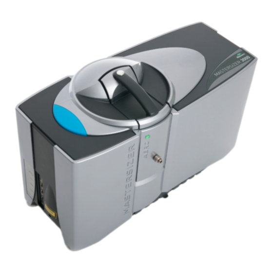
CHAPTER 4 HARDWARE FEATURES Mastersizer 3000/3000E Optical unit The following illustration shows the optical unit, the main component of the Mastersizer 3000 system. 6 4 1 Figure 4.2 The optical unit 1. Optical unit – Directs red and blue light through sample and collects the light scattered by the sample’s particles using detectors. -
Page 43: Connection Panel
CHAPTER 4 HARDWARE FEATURES 7. Adjustable feet – Important: adjust the feet individually to level the instrument on the bench. 8. Drain – Allows any spillages in the cell area to exit onto the laboratory bench. 9. Pipe/cable routing – Neatly routes all connection pipes and cables underneath the instrument. Connection panel The connection panel provides the communication and power connections. -
Page 44: Measurement Cell
CHAPTER 4 HARDWARE FEATURES Measurement Cell Cell components The following illustration shows the key parts of a wet cell. For a more detailed description of both the wet and dry cells, as well as the Hydro SV cell, refer to the Hydro or Aero Dispersion unit guides respectively: Figure 4.4 Key components of a wet cell. - Page 45 CHAPTER 4 HARDWARE FEATURES Inserting and removing the cell Always follow this process when inserting or removing the cell from the instrument. This sec- tion assumes that all relevant pipe connections between the dispersion unit and cell have already been made. Refer to the dispersion unit manuals for verification of these connections. Inserting the cell 1.
-
Page 46: Wet Dispersion Systems
CHAPTER 4 HARDWARE FEATURES Wet dispersion systems A wet system consists of the optical unit and at least one of the wet dispersion units (Hydro LV/MV/EV/SM or SV). The wet dispersion units are designed to circulate a liquid sample through the Mastersizer 3000's measurement cell. Figure 4.5 Typical wet dispersion unit installation. - Page 47 CHAPTER 4 HARDWARE FEATURES About the Hydro LV/MV The Hydro LV and MV are wet dispersion units designed to circulate a liquid sample through the Mastersizer 3000's measurement cell. Hydro LV and MV connections 2m max Figure 4.6 Hydro LV and MV connections. 1.
- Page 48 CHAPTER 4 HARDWARE FEATURES 3. Computer connection (USB) 7. Dispersant input: non-aqueous 4. Sample pipes to and from cell 8. Drain pipe to waste To allow liquid to drain efficiently the drain/waste must: Be within 2 m of the dispersion unit Be lower than the bench surface Slope gently downwards Contain no loops or kinks.
- Page 49 CHAPTER 4 HARDWARE FEATURES About the Hydro EV The Hydro EV is a wet dispersion unit designed to circulate a liquid sample held within a stand- ard glass beaker through the Mastersizer 3000's measurement cell. The filling and emptying of the glass beaker is a manual process. This unit is designed to create a suspension of particles in water or other liquid media.
- Page 50 CHAPTER 4 HARDWARE FEATURES 1. Power cable from External PSU 4. Sample pipes to and from cell 2. CAN cable 5. Heater/chiller connections (optional) 3. Computer connection (USB)
- Page 51 CHAPTER 4 HARDWARE FEATURES About the Hydro SM The Hydro SM enables the Mastersizer to be used measurements of smaller volumes of mater- ial than the EV but larger than the SV, typically 50-120 ml. This is ideal when the sample or dis- persant is toxic or expensive.
- Page 52 CHAPTER 4 HARDWARE FEATURES 2. CAN cable 6. Controller unit connection 3. Computer connection (USB) 7. Drain pipe to waste 4. Sample pipes to and from cell To allow liquid to drain efficiently the drain/waste must: Be within 2 m of the dispersion unit Be lower than the bench surface Slope gently downwards Contain no loops or kinks.
- Page 53 CHAPTER 4 HARDWARE FEATURES About the Hydro SV The Hydro SV manual dispersion unit is designed for the measurement of small amounts of a sample with a particle size typically less than 200 μm. Hydro SV connections Figure 4.9 Hydro SV connections. 1.
-
Page 54: Dry Dispersion System
CHAPTER 4 HARDWARE FEATURES Dry dispersion system Figure 4.10 Typical dry dispersion unit installation. 1. Optical unit – Measures the sample using red laser and blue light detection. Refer to Mastersizer 3000/3000E Optical unit on page 36 for a full description. 2. Dry dispersion unit – Circulates the sample through the cell. 3. - Page 55 CHAPTER 4 HARDWARE FEATURES About the Aero dry dispersion units The Aero dry dispersion units are designed for providing an even circulation of dry powder throughout Mastersizer 3000 / 3000E measurement cell. The Aero units allow the Mastersizer to be used for particle-in-gas particle size measurements; in the majority of cases the gas will be air.
- Page 56 CHAPTER 4 HARDWARE FEATURES Aero connections Figure 4.11 Aero connections. 1. Power cable from External PSU 7. Auxillary control cable 2. CAN/Power cable 8. Power cable to aucillary switch unit 3. Computer connection (USB) 9. Vacuum unit 4. Sample pipes to cell 10.
-
Page 57: Connection And Setup Overview
CHAPTER 4 HARDWARE FEATURES Note: Depending on the vacuum cleaner attached, an additional power cable (10) may be required. See Site requirements on page 21. Connection and setup overview Systems must be commissioned initially by a Malvern Panalytical representative. Com- missioning is the process of ensuring a that a safe physical installation of the Mastersizer 3000 has taken place together with a formal verification process to make sure that measurements are accurate. - Page 58 CHAPTER 4 HARDWARE FEATURES Note: It is important that the software is installed before the Mastersizer 3000/3000E instru- ment is connected to the computer and switched on. This will make sure that the instru- ment drivers are enabled, and that the firmware updates associated with this release are correctly downloaded to the instrument.
- Page 59 CHAPTER 4 HARDWARE FEATURES Sample flow connections Follow the connection details for Wet dispersion systems on page 40, or for Dry dispersion sys- tem on page 48. Also refer to the Aero and Hydro dispersion unit guides. System power up Powering on the system WARNING! Users must read and fully understand the Health and safety on page 5...
- Page 60 CHAPTER 4 HARDWARE FEATURES Note: Before using the instrument to measure a sample, wait for 30 minutes for the tem- perature to stabilize. Testing the system Use the following checks to verify that the system is still working correctly; these are especially important for testing the system after a move.
- Page 61 CHAPTER 4 HARDWARE FEATURES If the dispersion unit is not detected, the following is shown: Figure 4.14 Software indication that no accessory is detected. If this is the case, check the connection from the instrument to the dispersion unit. A blue pulsating power light on the dispersion unit indicates that it is connected correctly to the instru- ment.
- Page 63 CHAPTER 5 QUICK START: USING THE SYSTEM Making a Measurement Measuring samples in SOP mode Making a measurement — Wet dispersion units Making a measurement — Dry dispersion units Check the results Check for problems Running a Manual measurement...
-
Page 64: Making A Measurement
CHAPTER 5 QUICK START: USING THE SYSTEM Making a Measurement Introduction This chapter provides information on how to make an initial measurement using the Master- sizer after the system has been installed by a Malvern Panalytical engineer. Note: It is expected that the user already has a working knowledge of how the system works either from observing a demonstration during installation or from formal training. - Page 65 CHAPTER 5 QUICK START: USING THE SYSTEM This section describes how to create an SOP in order to make reproducible measurements. The example given uses the glass bead Quality Audit Standard (QAS) provided by Malvern Panalytical. Some degree of method development will be required to define settings that suit your own application and sample.
- Page 66 CHAPTER 5 QUICK START: USING THE SYSTEM Note: If any of the functions described in this section are unavailable, this could be due to your login credentials. Contact your system supervisor for assistance. 3. Make sure that the status bar indicates that the instrument is connected correctly: 4.
-
Page 67: Making A Measurement - Wet Dispersion Units
CHAPTER 5 QUICK START: USING THE SYSTEM Making a measurement — Wet dispersion units If you are using a wet dispersion unit (the Hydro LV/MV/EV/SM) work through the steps in the order given here. No manual control of the dispersion unit is required after loading the sample. The software controls all dispersion unit settings. - Page 68 CHAPTER 5 QUICK START: USING THE SYSTEM Figure 5.3 The Measurement display window. The progress status bar at the top of the window reports what is happening and shows what to do next. 4. Click the Start button to Initialize the instrument, automatically fill the tank and cell (Hydro LV/MV only) and then Measure Background (the system measures both the red and blue light values of the background).
- Page 69 CHAPTER 5 QUICK START: USING THE SYSTEM Figure 5.4 The Sample documentation window. 6. When this is complete, the SOP pauses. The system now requests that you add sample — do this until the Obscuration bar (in the Laser panel) indicates about 10-20%. This is a suit- able sample value for a wet dispersion unit.
-
Page 70: Making A Measurement - Dry Dispersion Units
CHAPTER 5 QUICK START: USING THE SYSTEM 8. Complete the measurement by closing the Measurement display window. 9. The measurement is complete. Proceed to the Checking the results section. Making a measurement — Dry dispersion units Note: Aero S is only compatible with the Mastersizer 3000 optical unit. This procedure assumes an Aero S dispersion unit is being used. - Page 71 CHAPTER 5 QUICK START: USING THE SYSTEM Figure 5.6 Aero dispersion unit sampling area. 1. Mesh baskets and ball bearing 4. Sample tray lock 2. Sample hopper and flow control 5. Venturi dispenser 3. Sample tray 1. Open the Aero S sample area lid and set the hopper flow rate to an appropriate gap level using the Sample hopper flow control dial (marked from 0–4 mm —...
-
Page 72: Check The Results
CHAPTER 5 QUICK START: USING THE SYSTEM Figure 5.7 The Measurement display. 6. Click Start . The SOP automatically turns on the air, aligns the optical system and then measures the background using red light. The sample tray starts vibrating and the air pres- sure specified in the SOP is applied. - Page 73 CHAPTER 5 QUICK START: USING THE SYSTEM Figure 5.8 Records within a measurement. Note: The illustration shows the results in a 2-pane view. Select View-2-pane Vertical from the View ribbon bar to activate this view. Create an average result An average result is very useful in assessing overall data quality. To create an average result; 1.
- Page 74 CHAPTER 5 QUICK START: USING THE SYSTEM Figure 5.9 Analysis report. Measurement Details — details about the measurement, such as sample name, operator and date of the measurement. Analysis — details about the analysis. Result — particle size measurement breakdown. Size Classes — histogram, which enables a quick visual analysis.
-
Page 75: Check For Problems
CHAPTER 5 QUICK START: USING THE SYSTEM The lower part of the display provides data showing the percentage of material at different points in the size distribution. For a QAS sample, all sample dispersion units should give a result showing a single peak with a median dv 50 between 58.77 and 64.9 µm. - Page 76 CHAPTER 5 QUICK START: USING THE SYSTEM “Noisy” data This can produce almost any pattern, but the pattern shown here is a typical example: Figure 5.11 Distribution histogram containing very large particles. Probably not enough sample added. Add more sample and measure again. Noisy data is also corroborated by a light energy graph (on the Data report) showing neither consistent nor significant light scattering across the range of detectors.
- Page 77 CHAPTER 5 QUICK START: USING THE SYSTEM Distribution with “tail” of particles This should not be seen when using the QAS standard. Figure 5.13 Distribution histogram with particle tail. Probably caused by agglomerates in the sample. Add new sample and measure again. Dirty windows Dirt on windows causes problems when the instrument initially reads the background.
-
Page 78: Running A Manual Measurement
CHAPTER 5 QUICK START: USING THE SYSTEM Running a Manual measurement Manual measurements follow a sequence of events: alignment, background measurement, adding sample (wet measurements only), sample measurement and cleaning. The system pauses between each of these stages and prompts you when intervention is required. 1. - Page 79 CHAPTER 5 QUICK START: USING THE SYSTEM Note: To reconfigure the measurement settings at any time during the measurement, click To stop one of the measurement processes whilst in progress, click 5. Wet measurements only — add sample until the obscuration is in range, observe the effect in the Laser display's Obscuration bar.
- Page 81 CHAPTER 6 MAINTENANCE General maintenance warnings Optical unit specific warnings Cleaning the covers Cleaning the cell bay Cleaning the Mastersizer 3000 optics Cleaning the cells and dispersion units Fuses...
-
Page 82: General Maintenance Warnings
CHAPTER 6 MAINTENANCE General maintenance warnings Note: Maintenance procedures and details of consumable parts kits for the Mastersizer 3000 dis- persion units are provided in their respective user manuals. WARNING! Do not attempt any maintenance procedure not specified here. Note: Before carrying out any maintenance operation, read and observe the all other safety warn- ings listed. -
Page 83: Cleaning The Covers
CHAPTER 6 MAINTENANCE Cleaning the covers CAUTION! The surfaces of the system may be permanently damaged if samples or dispersants are spilled on them. If a spillage occurs, disconnect the system from the power supply before carefully cleaning it up. Periodically clean the covers thoroughly using a mild soap solution. Never use excessive liquid for cleaning and always avoid electrical components (con- nectors etc.) and the cell windows. - Page 84 CHAPTER 6 MAINTENANCE Dust should be removed only using a specialist camera lens brush. Avoid handling the brush bristles as grease from fingers will be transferred to the optics. If unsure that the brush is clean, rinse it in ethanol and let it dry before use. CAUTION! Do not wipe the optics with an ordinary dry cloth;...
- Page 85 CHAPTER 6 MAINTENANCE Figure 6.1 The protection window. 1. Protection window 2. Finger access 1. Remove the cell from the instrument. 2. Make sure that the instrument is switched off and then disconnect the power supply to the instrument. 3. Using the finger recess, gently lower the protection window mounting so that it rests in the position shown in the illustration: 4.
-
Page 86: Cleaning The Cells And Dispersion Units
CHAPTER 6 MAINTENANCE Note: If placing the window on a bench to clean, make sure that it rests on a good quality lens tis- sue and not directly on the bench. It is also acceptable to immerse the window in a mild soap solution in order to clean it —... - Page 87 APPENDIX A ADDITIONAL INFORMATION Specification Chemical compatibility Regulatory information...
- Page 88 APPENDIX A ADDITIONAL INFORMATION Specification All specifications correct at time of publication, but may be subject to alteration. Mastersizer 3000 Optical unit Item Specification Size range: Mastersizer 3000 0.01 – 3500 μm* Size range: Mastersizer 3000E 0.1 – 1000 μm* Accuracy Better than 1%** Measurement principle Mie and Fraunhofer scattering Red light: Forward scattering, side scattering and back scat-...
- Page 89 APPENDIX A ADDITIONAL INFORMATION * Sample/preparation dependent. See dispersion unit guides for wet/ dry size ranges. ** Accuracy defined for the recovery of the mean size of a narrow lognormal distribution. Sample and sample preparation dependent. Hydro MV / Hydro LV Item Specification Dispersion type...
- Page 90 APPENDIX A ADDITIONAL INFORMATION Hydro EV Item Specification Dispersion type Capacity 600 ml / 1000 ml (standard laboratory beaker) 40 W max, 40 kHz (nominal)* Sonication power / frequency * Dispersant dependent. Typical applications Minerals, fillers, chemicals, foodstuffs, emulsions Dispersion mechanisms Continuously variable pump / stirrer and ultrasonics.
- Page 91 APPENDIX A ADDITIONAL INFORMATION Item Specification — Dispersion unit 8.75 kg Dimensions — Controller unit Width: 70 mm / Height: 225 mm / Depth: 170 mm — Dispersion unit Width: 390 mm / Height: 140 mm / Depth: 175 mm Supplied via CAN cable from the Optical unit 5 W —...
- Page 92 APPENDIX A ADDITIONAL INFORMATION Hydro series wet cell Item Specification Weight 2.46 kg Dimensions Width: 106 mm / Height: 273 mm / Depth: 227 mm Liquid temperature range 0 to 50°C (water jacket connections) Maximum pressure 0.5 bar g (water jacket connections) Aero S / Aero M Item Specification...
- Page 93 APPENDIX A ADDITIONAL INFORMATION Chemical compatibility Although the Mastersizer 3000 has been manufactured from materials considered to give the widest protection from chemical attack, it is important to check the chemical compatibility of a sample with any material with which it may come into contact. WARNING! It is advisable that the chemical compatibility is checked against the materials identified below before a sample is inserted.
- Page 94 APPENDIX A ADDITIONAL INFORMATION Hydro EV Component Materials Pump assembly Stainless steel 316 Stirrer PEEK (Glass fiber reinforced) Impeller Stainless steel 316 / PEEK Ultrasonic transducer Stainless steel 316 / Titanium nitride / PTFE Sample flow pipe (internal) Stainless steel 316 / PEEK (Natural) / FFKM / PTFE/ Sample flow pipe (external to wet cell) Tygon Wet cell assembly...
- Page 95 APPENDIX A ADDITIONAL INFORMATION Component Materials pipework (internal) Drain Valve Stainless steel 316 / PTFE / FFKM Drain pipe (internal) Stainless steel 316 / PTFE Drain pipe (external) PTFE / Acetal Sample flow pipe Stainless steel 316 / FEP/ PTFE/ FFKM (internal) Sample flow pipe Tygon...
- Page 96 APPENDIX A ADDITIONAL INFORMATION Component Materials Tygon (St R-3603) — standard* Sample flow pipe Tygon (MH2075 / HC F-4040-A) — Solvent compatible* (external to wet cell) * sample dependent Pipe connectors (at cell) Aluminum Wet cell assembly Borosilicate Glass / Stainless steel 316 / FKM or FFKM Hydro SV Component Materials...
- Page 97 APPENDIX A ADDITIONAL INFORMATION Regulatory information This section provides details of all applicable regulatory information. EU Declaration of Conformity The CE badge on this product signifies conformance to the relevant European Directives - con- sult the Declaration of Conformity certificate for the product for more information. VCCI acceptance (Japan only) The Voluntary Control Council for Interference (VCCI) mark on this product signifies compliance to Japanese EMC regulations as specified by VCCI.
- Page 98 APPENDIX A ADDITIONAL INFORMATION Cet appareil numérique de la classe A est conforme à la norme NMB-003 du Canada. FCC Notice (US only) The Federal Communications Commission (FCC) mark on this product signifies conformance to FCC regulations relating to Radio Frequency Devices. These have been satisfied by testing the product against, and being found to be compliant with: FCC CFR 47 Part 15:October 2011.Class A digital device.
- Page 99 APPENDIX A ADDITIONAL INFORMATION Refer to local regulations on disposal of equipment; in Europe refer to the information below. Seek advice from the local Malvern Panalytical representative for details. Decontaminate the instrument if hazardous materials have been used in it. The following is applicable in the European Union and other European countries with separate collection systems.
- Page 101 Health and safety INDEX Covers Electrical General Hydro dispersion units Laser Aero dispersion units Power cords Aero connections Site requirements Chemical compatibility Help Measuring samples Helpdesk Specifications Hydro dispersion units Hydro EV Hydro EV connections Chemical compatibility Hydro LV/MV Aero dispersion units Hydro LV/MV connections Cleaning Hydro SM...
- Page 102 Manual measurement Services Running Space required Measuring samples Software Aero dispersion units Install Hydro dispersion units SOPs Measuring samples Specifications Aero dispersion units Optical unit Hydro dispersion units Hardware Maintenance Moving Testing the system Specifications Website Power Powering the system Safety Power cords Power specification...
- Page 104 MALVERN PANALYTICAL Malvern Panalytical Ltd. Malvern Panalytical B.V. Grovewood Road, Malvern, Lelyweg 1, Worcestershire, WR14 1XZ, 7602 EA Almelo, United Kingdom The Netherlands Tel. +44 1684 892456 Tel. +31 546 534 444 Fax. +44 1684 892789 Fax. +31 546 534 598 MAN0475-07-EN-00 www.malvernpanalytical.com...
Need help?
Do you have a question about the Malvern Panalytical MASTERSIZER 3000 and is the answer not in the manual?
Questions and answers