
Related Manuals for Spectris SERVOMEX MonoExact DF150E


Summary of Contents for Spectris SERVOMEX MonoExact DF150E
- Page 1 MonoExact DF150E / DF310E Gas Analyzers Quick Start Guide PN: 0800000QSG UNRESTRICTED DOCUMENT...
- Page 2 + 44 (0) 1892 652 181 t: +1 800 433 2552 (US toll free) e: americas_sales@servomex.com e: europe_sales@servomex.com w: www.servomex.com w: www.servomex.com © 2020. Servomex Group Limited. A Spectris Company. All rights reserved © Servomex Group Limited 2022 Rev 800000QSG/001/A02...
-
Page 3: Table Of Contents
Contents Introduction ........................5 Safety ........................... 15 Installation and set-up ....................20 User interface ......................39 Technical specification ....................63 Rev 800000QSG/001/A02 © Servomex Group Limited. 2022 UNRESTRICTED DOCUMENT... - Page 4 Storage and disposal ....................66 Quick Start Guide P/N: 0800000QSG Revision: 800000QSG/2.2 © Servomex Group Limited 2022 Rev 800000QSG/001/A02...
-
Page 5: Introduction
Introduction About this Quick Start Guide 1.1.1 Scope of the Quick Start Guide This guide covers the installation, operation and routine maintenance of the MonoExact DF310E/DF150E analyzer. It is intended for those already familiar with the installation, use and maintenance of analytical or process instrumentation. General information on the analyzer is given in the main body of this guide. -
Page 6: Product Overview
This symbol warns of specific hazards due to Flammable Gas Samples which, if not taken into account, may result in personal injury or death. This symbol warns of specific hazards due to Toxic Gas Samples which, if not taken into account, may result in personal injury or death. This symbol highlights where you must take special care to ensure the analyzer or other equipment or property is not damaged. -
Page 7: General Description
Gas sample measurements are shown on the analyzer display,and can also be output to a serial device connected to the analyzer, or as milliamp (mA) / voltage outputs, or over a selection of digital communications protocols. Note: The MonoExact DF310E can have RS232 or RS485 communications, but only one can be active at a time. - Page 8 • OUTPUT: 1 Isolated 4-20mA (1 per option board, 4 max with 4 option boards) If Auto-Cal is purchased, then the following is included: • 8 Relays per transducer • 6 relays pre-assigned as Zero, Span, Sample gas per transducer •...
-
Page 9: Recommended Calibration Intervals
Recommended calibration intervals For optimum performance, it is necessary to routinely check the calibration of all the internal gas transducers within the analyzer. The recommended periods for each transducer type are shown in Section Error! Reference source not found.. This guide provides details of the following: •... -
Page 10: Product Identification
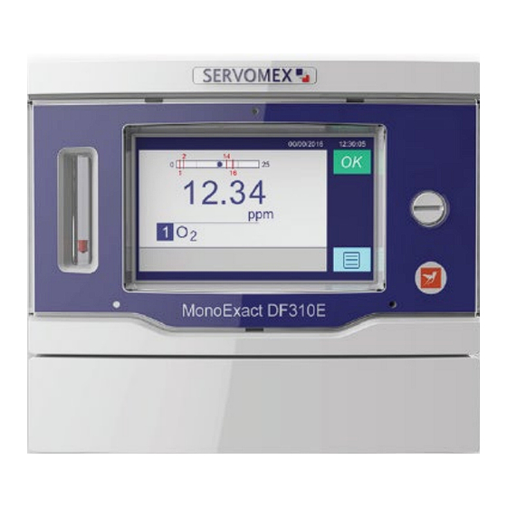
Note: When the Auto-Cal option has been purchased, the manual calibration process will use the Auto-Cal valves to select the required calibration gas. Product identification Figure 1-1: The MonoExact DF310E Gas Analyzer © Servomex Group Limited 2022 Rev 800000QSG/001/A02... - Page 11 Figure 1-2: Rear of the MonoExact DF310E Gas Analyzer Rev 800000QSG/001/A02 © Servomex Group Limited. 2022 UNRESTRICTED DOCUMENT...
- Page 12 Description Description J1 – J2 Relay I/O connections Analog and digital inputs 4 – 20 mA output / analog inputs RS485 (Modbus) (optional) Note: A legacy 4-lead cable can be connected to the top 4 connections labeled I1+, I1-, V1+ and V1-. General purpose digital inputs Moisture probe input that can be used in future...
- Page 13 Figure 1-3: Rear of the MonoExact DF150E Gas Analyzer Description J1 – J2 Relay I/O connections Earth (ground) connection Rev 800000QSG/001/A02 © Servomex Group Limited. 2022 UNRESTRICTED DOCUMENT...
-
Page 14: Sample Requirements
Sample requirements For best performance the flow supplied to the analyzer should be kept constant and the analyzer must be freely vented to atmosphere, for both process sampling and for calibration gas input. Flow Rate: Nominal 500 mL/min (Min 250 mL/min, Max 1000 mL/min) Pressure: Pressure driven: 172.36-310.26 kPa;... -
Page 15: Safety
Safety Appropriate environmental monitoring, ventilation and gas safety controls The user is solely responsible for implementing appropriate environmental monitoring, ventilation and gas safety controls for flammable and/or toxic gas installations to meet all relevant safety standards including but not limited to those imposed by legal, governmental, statutory, industrial, regulatory and/or corporate requirements. -
Page 16: Chemical Warnings
The MonoExact DF310E/DF150E analyzer may be attached to equipment that is hot. Always wear the appropriate PPE to minimize the risk of burns. This symbol warns of specific hazards due to hazardous substances which, if not taken into account, may result in personal injury or death. This symbol warns of specific hazards due to caustic or corrosive substances which, if not taken into account, may result in personal injury or death. -
Page 17: Electrical Warnings
Electrical warnings Always observe the appropriate electrical safety codes and regulations. Make sure that the electrical installation of the analyzer conforms with all applicable local and national electrical safety requirements. Potentially hazardous AC voltages are present within this instrument. Leave all internal servicing to qualified personnel. Disconnect the AC power source before installing or removing any external connections. - Page 18 To provide an acceptable noise environment for the MonoExact DF310E/DF150E analyzer or other digital equipment in the proximity of switching inductive loads, Servomex recommends that you place varistors across the inductors to lessen high voltage spikes that occur during transitions. Circuitry activated by relay contacts should allow for the contact bounce.
- Page 19 Do not connect any cables carrying mains voltage or cables that have inadequate insulation between line and mains to any of the I/O connectors. Earth / ground connections. These are screw terminals used to connect the ground shields of cables plugged into the nearby connectors.
-
Page 20: Installation And Set-Up
Installation and set-up Do not attempt to install, commission, maintain or use the MonoExact DF310E/DF150E analyzer unless you have been trained or are an experienced instrument technician. The MonoExact DF310E/DF150E analyzer is only suitable for installation in safe areas. Follow the instructions in this section to safely install the MonoExact DF310E/DF150E analyzer. - Page 21 • Figure 3-1: Gas inlets and outlets on rear of the analyzer Hint: If you do not intend to use the analyzer immediately, replace the protective plastic covers and remove them just before connecting into the process sample pipework fitting. 3.
- Page 22 Transducer specific installation 3.2.1 Coulometric transducer Adding electrolyte The electrolyte is a caustic solution. Review the Material Safety Data Sheet (MSDS) before handling the electrolyte solution. The sensor is shipped dry and must be charged with electrolyte before it is operated. Do not ship the analyzer with electrolyte –...
-
Page 23: Mechanical Installation
Completely loosen the bracket retaining thumbscrew immediately in front of the sensor (Figure 3-2). Slide the sensor assembly back slightly, then upwards to move the sensor to a position just in front of the analyzer. Unscrew the blue sensor cap from the electrolyte reservoir and add the entire contents of one bottle (125 ml) of Ɛ-lectrolyte Blue to the sensor. -
Page 24: Rack Mounting
Figure 3-3: Panel installation Refer to Figure 3-3. Prepare a cut-out in a suitable panel. Prepare a suitable base support and secure it in your frame or cabinet. If the bolts and washers are supplied separately, use them to fit the left- and right- hand mounting brackets to the analyzer. - Page 25 Figure 3-4: Rack installation Figure 3-5: Dual rack installation Refer to Figure 3-4 Figure 3-5 and install the analyzer as follows: If the rack mounting kit has been supplied as a spare: Remove the two slide inner sections from the two slide outer sections. Use the supplied M5 screws to fit the two slide inner sections to the sides of the analyzer.
-
Page 26: Electrical Installation
Install cage nuts in positions 1, 3, 4, and 7 on the left-hand and right-hand front rack enclosure flanges. Install cage nuts in positions 1 and 4 on the left-hand and right-hand rear rack enclosure flanges. Engage the two M6 waisted screws into the cage nuts in positions 1 and 4 on the left- hand and right-hand front and rear rack enclosure flanges. -
Page 27: Analog Output Signal Connections
Make sure the electrical supply plug is easily accessible for disconnection from the electrical supply. Make sure the analyzer is provided with a sound earth connection via the electrical supply plug. All signal and electrical supply cables must be rated for temperatures of 70°C or higher. -
Page 28: Relay Connections
Table 3-1: Analog output interface connector (J14 and J5) Note: Unless specified differently, an analog Vdc output is provided as standard across pins 1 and 2. (A mA analog output is optional). Note: If your analyzer is configured to provide voltage outputs, connect the wires to pins 4 –... - Page 29 Note: When Auto-Cal is purchased, the coulometric transducer has 8 relays available with 3 relays preassigned - the 6 assigned to Zero, the 7 to Span and the 8 the Sample gas. The 1 to the 5 relays can be assigned to any alarm or function even if it is not related to the coulometric measurement.
- Page 30 Table 3-4: Relay interface connector J2 (DF310E) Connector Relay Relay Relay Relay Relay Relay Table 3-5: Relay interface connector J7, J9, J10 – J13 (DF310E) DF150E The DF150E analyzer has a number of relays available via the connectors J1 and J2 as Table 3-7 Table 3-8 shown in...
- Page 31 Connect the wires in your cable to the screw terminals on the relevant connectors as shown in the following tables: Note: Section 5.2 for information on the rating and size of cable. J1 Pin Relay J1 Pin Relay RANGE 3 RANGE 2 RANGE 1 SENSOR OFF COM...
-
Page 32: Connect The Electrical Supply
The 4 to 20 mA output is electrically isolated from all other analyzer outputs and from the chassis (earth) ground. The maximum load resistance is 1 kΩ. The analyzer provides a loop supply of approximately 28 Vdc. Connections to the 4-20 mA output should be through a shielded, twisted pair with the shield tied to the nearest ground stud. - Page 33 Figure 3-6: Power switch (A) and electrical supply socket (B) on rear of analyzer Plug the other end of the electrical supply cable into your electrical supply outlet. Check the earth (ground) continuity between your electrical supply outlet earth (ground) and the functional earth (ground) terminal on the rear of the analyzer. If a local earth bonding is required, the functional earth stud can be used.
- Page 34 Sample and calibration gases may be toxic or asphyxiant: Make sure that the external connections are leak free at full • operating pressure before you use sample or calibration gases. Make sure that the sample/bypass outlet pipes are vented to an •...
- Page 35 Figure 3-7: Gas inlets and outlets on rear of analyzer The sample gas inlet and outlet lines at the back of the instrument have stainless steel ⅛ inch compression bulkhead fittings (unless equipped with the optional ¼ inch VCR inlet). Before connecting any gas line to the analyzer, fully install the supplied gas nut and compression ferrule on your tubing.
-
Page 36: Switch Off The Analyser
View flow levels The optional flow meters are visible on the front panel and are calibrated for use with air / . The flowmeter should be read at the top of the flow bead. Most other gases have molecular weights within ± 25 percent of air and will produce valid readings. If the molecular weight of the background gas is much different from air / N the flowmeter reading will be less accurate. - Page 37 Power up Sample and calibration gases may be toxic or asphyxiant: Make sure that the external connections are leak free at full • operating pressure using N or Zero Air before you use sample or calibration gases. Make sure that the sample/bypass outlet pipes are vented to an •...
- Page 38 Figure 3-9: On/Off switch on the rear of the analyzer, (A) points to the Power Switch “I” for ON position. When the analyzer is first switched on, the screen displays a progress bar, followed by the 3-10). Home screen (Figure Figure 3-10: Home screen ©...
-
Page 39: User Interface
User interface User interface overview Configuration options referred to in this guide (for example, auto-calibrate / validate) must be specified at the time of purchase. The menus and menu options associated with the options not purchased will appear as grey colored icon buttons (as seen in the red box of Error! Reference source not found.) and will be unavailable for use. - Page 40 For example, to reach the Alarms screen (a sub-screen of the Measurement branch) you must press the following sequence of icons: Touch the icon to display the Main Menu screen. Next, touch the icon to display the Measurement screen. Finally, touch the icon to display the Alarms screen.
- Page 41 Note: Be sure not to press too hard or you will damage the screen; do not use the point of a pen or pencil to touch the screen. For example, the sequence used to arrive at the screen shown in Figure 4-2 is accessed by touching the Main Menu icon on the Home page then touching the Measurement icon...
- Page 42 > • The first series of functional icons that belong to the Settings section are displayed in the column of icons to the right of the Main Menu icons (Figure 4-3 A). > > • To display the next set of functions touch which brings up the second set of Setting functions (Figure 4-3 C) to the right of the first set (Figure 4-3 A).
-
Page 43: Home Screen
Home screen The Home screen (Figure 4-4) displays the current measurement and system status. C, D Figure 4-4: Single Gas Home screen components Bar graph showing the operable Information area where messages measurement range boundaries, such as error codes, IP address, current measurement and relative and diagnostic information are to alarm set points... - Page 44 Main Menu screen icons Main Menu Icon Four Main Menu Branches Figure 5-11: Menu screen The Main Menu icons are listed below: Icon Meaning Function Measurement Displays the Measurement screen where measurement, calibration / validation and alarm settings can be adjusted for each transducer installed (Section 6).
- Page 45 4.5.1 Frequently Used Touchscreen icons The following table shows touchscreen icons that frequently appear on different screens. The Main Menu Icons are highlighted as bold text under the “Meaning” column below. Table 4-1: Frequently Used Touchscreen icons: Icon Meaning Function Located on the Home screen (Error! Reference source Menu not found.) displays the Menu screen of the four...
- Page 46 System and measurement status icons and notices The Status icon is located at the top right corner of the Home screen. If the system is operating correctly the green OK icon is displayed (Figure 4-5). Figure 4-5: Home screen (three gas transducers) Note: If you touch the green OK icon it will display the date and time when the analyzer was last started.
- Page 47 Figure 4-6: Home screen showing O alarm Figure 4-7: Home screen, showing warning screen with fault description Note: In Figure 4-7 the fault icon was touched and “C: COMMS fault” was displayed in the message area bottom of screen Analyzer Menu Branch Structure Menu branch structure Section 4.7.1 describes the top-level Main Menu structure and directs you to the subsections that show the buttons available under each of the main menu branches.
- Page 48 4.7.1 Top level structure Home Menu Measurement > > Section 4.7.2 Diagnostics > Section 4.7.3 Maintenance > Section 4.7.4 Settings > Section 4.7.5 4.7.2 Measurement Note: Each Alarm and Relay have their own settings. Only one set is shown here as example.
- Page 49 Measurement Measurement Measurement Measurement Level 1 Button Level 2 Button Level 3 Button Level 4 Button Alarms Meas. Value alarm Meas. Value High Meas. Value Low Meas. Alarm Value Threshold Numeric Keypad Meas. Alarm Value Hysteresis Numeric Keypad Audible Alarm On / Off Alarm Following On / Off...
- Page 50 Measurement Measurement Measurement Measurement Level 1 Button Level 2 Button Level 3 Button Level 4 Button Transducer Temp Transducer Temp Alarm Value High Transducer Temp Value Low Transducer Temp Alarm Value Numeric Keypad Threshold Transducer Temp Alarm Value Numeric Keypad Hysteresis Audible Alarm Transducer Temp...
- Page 51 Measurement Measurement Measurement Measurement Level 1 Button Level 2 Button Level 3 Button Level 4 Button Span Reference Span Ref Alarm Alarm (cont.) Value Hysteresis Numeric Keypad Audible Alarm On / Off Alarm Following Alarm active during On / Off calibrations Span Reference Alarm Latching...
- Page 52 Measurement Measurement Measurement Measurement Level 1 Button Level 2 Button Level 3 Button Level 4 Button Analog Output Follow Meas. Value Settings During Cal On / Off Output Adjustment Numeric Keypad for μA and 0-10 mVDC micro adjustments Jam Condition Analog Output Settings (cont.) Zero...
- Page 53 Measurement Measurement Measurement Measurement Level 1 Button Level 2 Button Level 3 Button Level 4 Button Process Stream AquaXact Pressure Pressure Comp Numeric Keypad Pressure Comp On/Off Coulometric sensor Enter Offset Integer option GSF Advance Select Gas Mix = Coulometric sensor 100% option Filter Type 1...
- Page 54 Measurement Measurement Measurement Measurement Level 1 Button Level 2 Button Level 3 Button Level 4 Button Coulometric External Input 1 or 2 Use external input 1 or On / Off Use external input 1 or 2 to turn sensor on / 2 to turn pump on / off Change Dew Point Celsius...
- Page 55 Measurement Measurement Measurement Measurement Level 1 Button Level 2 Button Level 3 Button Level 4 Button Auto-Calibration Setup Transducer Scheduled Event Run Auto-Calibration Sequence Selection Settings (cont.) (#1, #2, #3) Abort Auto- Calibration Set Auto-Calibration Date / Time / Repeats Electrolyte Replenishment Number of days...
- Page 56 4.7.3 Diagnostics Diagnostics Diagnostics Diagnostics Diagnostics Level 1 Button Level 2 Button Level 3 Button Level 4 Button Software revision Screen displays operating system version Analyzer Chassis Temperature sensor Temp is located on the display PCB Analyzer SN Serial number of analyzer System File Save Save analyzer...
-
Page 57: Maintenance
4.7.4 Maintenance Maintenance Maintenance Maintenance Maintenance Level 1 Button Level 2 Button Level 3 Button Level 4 Button System updates Update Firmware firmware to version Only one firmware Firmware code in top on USB memory code version per USB USB directory stick Disk Space Screen Indicator for... - Page 58 Settings Settings Settings Settings Level 1 Button Level 2 Button Level 3 Button Level 4 Button Serial Port Setup Full Duplex (cont.) Half Duplex RS485 only 1 Stop Bit 2 Stop Bits Baud Rate Setting 1200, 1800, 2400, 4800, 9600, 19200, 38400, 76800, 115200 None Parity...
- Page 59 Settings Settings Settings Settings Level 1 Button Level 2 Button Level 3 Button Level 4 Button Serial Port Setup RS485 Functions Modbus Word Mirror image of Swapping: On / OFF (cont.) (cont.) Modbus communications Relay Select Transducer Alarm Assignment Assignment Measurement #1, #2, etc.
- Page 60 Settings Settings Settings Settings Level 1 Button Level 2 Button Level 3 Button Level 4 Button Password Setup Keystroke Recording Records every icon On / Off (cont.) button touched in sequential order Manual Relay Normal Operation – Override Relay ON Icon background blue Normal Operation –...
- Page 61 Settings Settings Settings Settings Level 1 Button Level 2 Button Level 3 Button Level 4 Button Digital Inputs Choose Digital Input Start Span Cal (cont.) #3 or #4 for assignment Disable Digital Input Pump On / Off MEDF-310E and Pump On / Off MEDF-150E External Input 1 or 2 Use external input 1 or...
- Page 62 Settings Settings Settings Settings Level 1 Button Level 2 Button Level 3 Button Level 4 Button Adjust Decimal Reduce the number Places of decimal places to the limit of the sensor Block Time Measurement Averaging Averages measurements over a selected period of time ©...
-
Page 63: Technical Specification
Technical specification The protection, accuracy, operation and condition of the equipment may be impaired if the analyzer is not installed in accordance with the requirements of this and other sections of the manual. Mechanical specification Dimensions: (Length x Height x Width) Rack mountable analyzer: Without 19-inch rack mounting brackets: 236 x 193 x 205 mm... - Page 64 Voltage output (active): Minimum load resistance: 100 kΩ Isolation voltage (to earth): 250 V (dc or ac) Output range: Normal sample measurement: 0 to 10 V Fault condition: Fault condition selected as an option at the time of purchase. Under range: Not applicable Signal / voltage / mA / RS485 output terminals suitable for:...
-
Page 65: Environmental Limits
Signals: Maximum voltage rating: Environmental limits The equipment is suitable for indoor use only. Ambient temperature range: Operation: 5 to 45 °C Storage: 0 to 50 °C Operating ambient pressure range: 101.3 kPa ± 10% (1.013 bar ± 10%) Operating ambient humidity range: 10 to 90% RH, non-condensing Operating altitude range: -500 metres (below sea level) to 2000 metres... -
Page 66: Storage And Disposal
Storage and disposal Storage Refit any protective plastic covers and place the analyzer and any associated equipment in its original packaging before storage. Alternatively, seal it inside a waterproof plastic bag, sack, or storage box. Store the analyzer and any associated equipment in a clean, dry area. Do not subject it to excessively hot, cold, or humid conditions. -
Page 67: Applicable Eu Directives
Applicable EU Directives Low Voltage Directive: 2014/35/EU Electromagnetic Compatibility (EMC) Directive: 2014/30/EU Applicable standards EN 61010-1:2010 EN 61326-1:2013 / IEC 61326-1:2012 EN15267-3:2007 MCERTS Performance Standards for CEMS CLASS – C225206 PROCESS CONTROL EQUIPMENT CLASS – C225286 PROCESS CONTROL EQUIPMENT Certified to US Standards Rev 800000QSG/001/A02 ©... -
Page 68: Material Safety Data Sheet
Material Safety Data Sheet Identification of the substance Trade name ElectrolyteSolution, Ɛ-lectrolyte Gold, Ɛ-lectrolyte Blue, Ɛ-lectrolyte Black, DF-E05, DF-E06, DF-E07, DF-E09 Manufacturer Servomex, Inc. Boston Technical Center 4 Constitution Way, Woburn, MA 01801-1087, USA, Tel + 1-781-935-4600 Emergency contact ChemTel Expert Assistance Hotline USA: 1-800-255-3924 International: +01-813-248-0585 Composition... - Page 69 Skin Contact Causes skin burns. May cause deep, penetrating ulcers of the skin. Ingestion May cause circulatory system failure. May cause perforation of the digestive tract. Causes severe digestive tract burns with abdominal pain, vomiting, and possible death. Inhalation Inhalation under normal use would not be expected as this product is supplied as an aqueous solution and no hazardous vapors are emitted.
- Page 70 Fire-fighting measures Special Exposure Hazard Not applicable Extinguishing Media Not Combustible. Select extinguishing media appropriate to the surrounding fire conditions. Protective Equipment Wear appropriate protective clothing to prevent contact with skin and eyes. Wear a self-contained breathing apparatus (SCBA) to prevent contact with thermal decomposition products.
- Page 71 Respirators Not Applicable. Inhalation under normal use would not be expected as this product is supplied as an aqueous solution and no hazardous vapors are emitted. Airborne Exposure This material is supplied as an aqueous solution and will not be present in the atmosphere in normal use.
- Page 72 Hazardous Decomposition Oxides of potassium Products Hazardous Polymerization Has not been reported Toxological information RTECS# CAS# 7732-18-5 ZC0110000 CAS# 1310-58-3 TT2100000 LD50/ LC50 CAS# 7732-18-5 Oral, ret:LD50 = >90 ml/kg CAS# 1310-58-3 Draize test, rabbit, skin: 50 mg/24H Severe Oral, rat: LD50 = 273 mg/kg Carcinogen Status CAS# 7732-18-5 Not listed by ACGIH, IARC, NIOSH, NTP, or OSHA...
- Page 73 Transportation information Shipping Name Hazard Packaging Class Number Group US DOT Potassium Hydroxide UN1814 Solution IATA Potassium Hydroxide UN1814 Solution ADR/RID Potassium Hydroxide UN1814 Solution IMDG Code Potassium Hydroxide UN1814 Solution Canadian TDG Potassium Hydroxide 8(9.2) UN1814 Not available Solution Regulatory information US Federal TSCA...
- Page 74 Does not contain any Class 1 Ozone depletors Does not contain any Class 2 Ozone depletors Clean Water Act CAS# 1310-58-3 Listed as a Hazardous Substance under the None of the chemicals are listed as Priority Pollutants under the CWA None of the chemicals are listed as Toxic Pollutants under the CWA OSHA...
- Page 75 In case of accident or if you feel unwell, seek medical advice immediately (show label where possible). WGK (Water CAS# 7732-18-5 No information available Danger/Protection) CAS# 1310-58-3 Canada – DSL/ NDSL CAS# 7732-18-5 Listed on Canada’s DSL List CAS# 1310-58-3 Listed on Canada’s DSL List Canada - WHMIS Classification E,...
Need help?
Do you have a question about the SERVOMEX MonoExact DF150E and is the answer not in the manual?
Questions and answers