
Related Manuals for Spectris Particle Measuring Systems Airnet II 301


Summary of Contents for Spectris Particle Measuring Systems Airnet II 301
- Page 1 Without measurement there is no control Airnet® II Particle Sensors 301, 501, 501A, 510, 510XR, 510s, 510s XR OP E RAT I ON S M A N UA L P/N 1000014015...
- Page 2 Airnet® II Particle Sensors 301, 501, 501A, 510, 510XR, 510s, 510s XR Operations Manual HEADQUARTERS 5475 Airport Blvd BRAZIL JAPAN SINGAPORE Boulder, Colorado 80301 USA T: +55 11 5188 8227 T: +81 3 5298 8175 T: +65 6496 0330 T: +1 303 443 7100, +1 800 238 1801 E: pmsbrazil@pmeasuring.com E: pmsjapan@pmeasuring.com E: pmssingapore@pmeasuring.com...
-
Page 3: Quality Statement
Airnet II Particle Sensors 301, 501, 501A, 510, 510XR, 510s, 510s XR Operations Manual P/N 1000014015 Rev F © 2019 by Particle Measuring Systems, Inc. All rights reserved. ® Airnet is a registered trademark of Particle Measuring Systems, Inc. ® HyperTerminal is a registered trademark of Hilgraeve, Inc. -
Page 4: Manual Conventions
Manual Conventions WARNING A warning in the text is used to notify the user of the potential for bodily injury or death. CAUTION A caution in the text is used to highlight an item that if not done, or incorrectly done, could damage the instrument and/or any materials or devices affected by the instrument. -
Page 5: Ce - Declaration Of Conformity
CE – Declaration of Conformity - Declaration of Conformity Application of Council Directive(s): 2014/30/EU, 2014/35/EU, RoHS 2011/65/EU Standard(s) to which Conformity is Declared: EN 61326-1: 2013 Safety EN 61010-1: 2010, 3rd Ed. EN 60825-1: 2014 Manufacturer’s Name: Particle Measuring Systems, Inc. Manufacturer’s Address: 5475 Airport Boulevard, Boulder, CO 80301 USA Manufacturer’s Telephone/FAX:... -
Page 6: Table Of Contents
Table of Contents Quality Statement - - - - - - - - - - - - - - - - - - - - - - - - - - - - - - - - - - - - - - - - - - ii Environmental Information - - - - - - - - - - - - - - - - - - - - - - - - - - - - - - - - - - - ii Patent Information - - - - - - - - - - - - - - - - - - - - - - - - - - - - - - - - - - - - - - - - - ii Manual Conventions - - - - - - - - - - - - - - - - - - - - - - - - - - - - - - - - - - - - - - - - iii... - Page 7 Setting Configuration Addresses for Ethernet- - - - - - - - - - - - - - - - - - 3-3 Configuration Commands - - - - - - - - - - - - - - - - - - - - - - - - - - - - - - - - - 3-4 Viewing Configuration Settings - - - - - - - - - - - - - - - - - - - - - - - - - - - - - 3-7 Connecting the Ethernet Cable - - - - - - - - - - - - - - - - - - - - - - - - - - - - - 3-7 Chapter 4: 4-20 mA Signal Configuration / Operation- - - - - - - - - - - - - - - - - - - - - - 4-1...
- Page 8 AVERTISSEMENT - - - - - - - - - - - - - - - - - - - - - - - - - - - - - - - - - - - - - - - - - - - D-1 WARNUNG - - - - - - - - - - - - - - - - - - - - - - - - - - - - - - - - - - - - - - - - - - - - - - - - D-1 ATTENZIONE - - - - - - - - - - - - - - - - - - - - - - - - - - - - - - - - - - - - - - - - - - - - - - D-1 ADVERTENCIA- - - - - - - - - - - - - - - - - - - - - - - - - - - - - - - - - - - - - - - - - - - - - - D-1...
- Page 9 This page is intentionally left blank. viii Airnet II Particle Sensor Operations Manual...
-
Page 10: List Of Figures
List of Figures Chapter 1: Getting Started - - - - - - - - - - - - - - - - - - - - - - - - - - - - - - - - - - - - - - - - - - - 1-1 Figure 1-1 Airnet II Models 301, 501, 510, and 510XR - - - - - - - - - - - - - - - - - - - - - - - - 1-2 Figure 1-2 Airnet II Models 510s and 510s XR - - - - - - - - - - - - - - - - - - - - - - - - - - - - - - 1-2 Figure 1-3 Airnet II (polycarbonate enclosure) LEDs and connections - - - - - - - - - - 1-6... - Page 11 Appendix D: International Precautions - - - - - - - - - - - - - - - - - - - - - - - - - - - - - - - - - D-1 Appendix E: - - - - - - - - - - - - - - - - - - - - - - - - - - - - - - - - - - E-1 Airnet II Particle Sensor Operations Manual...
-
Page 12: List Of Tables
List of Tables Chapter 1: Getting Started - - - - - - - - - - - - - - - - - - - - - - - - - - - - - - - - - - - - - - - - - - - 1-1 Table 1-1 Airnet II Particle Sensor Specifications - - - - - - - - - - - - - - - - - - - - - - - - - 1-8 Table 1-2 Airnet II Particle Sensor Environmental Conditions - - - - - - - - - - - - - - - - 1-11 Chapter 2: Unpacking and Installation- - - - - - - - - - - - - - - - - - - - - - - - - - - - - - - - - - 2-1... - Page 13 Appendix C: RJ45 Data Connector Installation - - - - - - - - - - - - - - - - - - - - - - - - - - - C-1 Appendix D: International Precautions - - - - - - - - - - - - - - - - - - - - - - - - - - - - - - - - - D-1 Appendix E: - - - - - - - - - - - - - - - - - - - - - - - - - - - - - - - - - - E-1 Airnet II Particle Sensor Operations Manual...
-
Page 14: Chapter 1: Getting Started
Chapter 1 Getting Started The Airnet II particle sensor is a laser-optical aerosol particle sensor that accurately detects, counts, and measures particles suspended in air. This manual includes information on operating the following Airnet II models: • 301 • 501, 501A, 510, and 510XR •... -
Page 15: Figure 1-1 Airnet Ii Models 301, 501, 510, And 510Xr
Chapter 1 Getting Started Figure 1-1 Airnet II Models 301, 501, 510, and 510XR Figure 1-2 Airnet II Models 510s and 510s XR Page 1-2 Airnet II Particle Sensor Operations Manual... -
Page 16: Class I Laser Product
Chapter 1 Getting Started Class I Laser Product The Airnet II particle sensors are Class 1 laser products. WARNING This instrument is a Class 1 laser product. Use of controls, adjustments, or performance of procedures other than those specified here may result in hazardous radiation exposure. -
Page 17: Physical Description
Chapter 1 Getting Started Physical Description Two LEDs are located on the top of each Airnet II particle sensor chassis: • Status LED – Indicates the operational status of the instrument. • Activity LED – Flashes when a particle is detected. When connected to Facility Net software, the LED is controlled by Facility Net’s alarm settings. -
Page 18: Instrument Connections
Chapter 1 Getting Started Instrument Connections Airnet II 301, 501, 501A, 510, and 510XR (Polycarbonate enclosure version): All connectors are found on the back of the unit’s chassis, including: • Electrical Power – Power can be provided through the 24 VDC power connector (see Figure 2-6 on page 2-7) or though the Ethenet connection if Power over Ethernet (PoE) is being utilized. -
Page 19: Figure 1-3 Airnet Ii (Polycarbonate Enclosure) Leds And Connections
Chapter 1 Getting Started Sample Inlet Status and Activity LEDs Airnet II 301, 501, 501A, 510, 510XR Figure 1-3 Airnet II (polycarbonate enclosure) LEDs and connections Page 1-6 Airnet II Particle Sensor Operations Manual... -
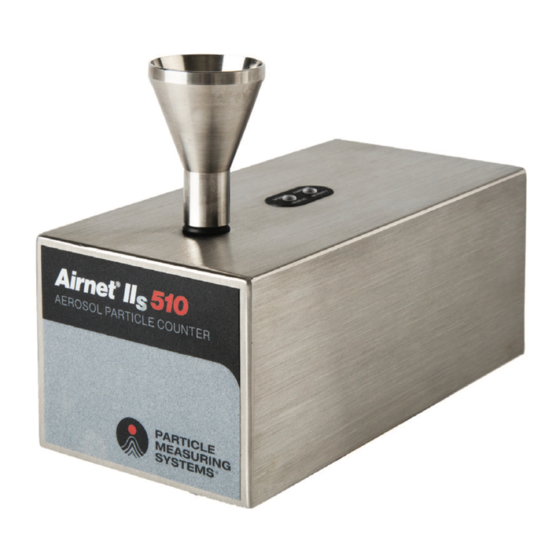
Page 20: Figure 1-4 Airnet Ii (Stainless Steel Enclosure) Connections
Chapter 1 Getting Started Airnet II 510s, and 510s XR (Stainless steel enclosure version): All connectors are found on the bottom of the units’ chassis, including: Ethernet connector – For data transferring and power over Ethernet powering (PoE). • Ethernet - The UTP Ethernet connector allows the unit to communicate with FacilityPro and Facility Net by connecting an Ethernet cable from the particle sensor to the Ethernet hub. -
Page 21: Specifications
Chapter 1 Getting Started Specifications Table 1-1 Airnet II Particle Sensor Specifications 501A 510s 510 XR 510s XR 0.3 and 0.5 0.5 and 5.0 0.5 and 1.0 0.5 and 5.0 Channel thresholds (µm) 0.1 CFM 0.1 CFM 0.1 CFM 1.0 CFM Sample flowrate (2.8 LPM) (2.8 LPM) -
Page 22: Product Dimensions
Chapter 1 Getting Started Product Dimensions Figure 1-5 Airnet II (polycarbonate exterior) dimensions Airnet II Particle Sensor Operations Manual Page 1-9... -
Page 23: Figure 1-6 Airnet Iis (Stainless Steel Exterior) Dimensions
Chapter 1 Getting Started Figure 1-6 Airnet IIs (stainless steel exterior) dimensions Figure 1-7 Wall mounting bracket dimensions Page 1-10 Airnet II Particle Sensor Operations Manual... -
Page 24: Environmental Conditions
Chapter 1 Getting Started Environmental Conditions The following environmental conditions apply to the Airnet II particle sensor: Table 1-2 Airnet II Particle Sensor Environmental Conditions Operating temperature 4 – 35°C Humidity conditions 5 – 95% RH, non-condensing Storage and transportation - 10°... - Page 25 Chapter 1 Getting Started This page is intentionally left blank. Page 1-12 Airnet II Particle Sensor Operations Manual...
-
Page 26: Chapter 2: Unpacking And Installation
Chapter 2 Unpacking and Installation Unpacking 1. Carefully open the container and remove the Airnet II particle sensor. 2. Ensure that all components listed in the following section are included, and inspect each unit for any damage. 3. If any components are damaged, immediately notify the shipper and Particle Measuring Systems. -
Page 27: Shipping List
Chapter 2 Unpacking and Installation Shipping List Airnet II 301, 501, 501A, 510, and 510 XR (Polycarbonate enclosure version): Table 2-1 Airnet II Particle Sensor Shipping List (Polycarbonate) Part Name Quantity Isokinetic air sampler (probe) “L” Type mounting bracket (or one of three alternate brackets Phone jack cable, RS-232 Operations manual Universal AC to DC power supply 100 –240 VAC, 50/60 Hz... -
Page 28: Items You Need To Provide
Chapter 2 Unpacking and Installation Items You Need to Provide The following items are not included, and you will need to provide: • Ethernet cable • 4-20 mA cable (necessary only if 4-20 mA signal output is used) • Computer •... -
Page 29: Automated Laser Power Control
Chapter 2 Unpacking and Installation Automated Laser Power Control Airnet II particle sensor units contain an automated laser power control that automatically shuts off the laser power after 10 seconds of continuous bad flow. The laser power is restored after 10 seconds of continuous good flow. Detector Board Monitor The Airnet II particle sensor has an automatic monitor to assure the detector board is operating correctly. -
Page 30: Selecting A Location
Chapter 2 Unpacking and Installation Selecting a Location When choosing the location for the Airnet II particle sensor(s), consider the following to improve the utility of the unit. Sample Point – Position the particle sensor to ensure that the sampling probe is pointed INTO the airflow you want to monitor. -
Page 31: Positioning Or Mounting The Unit
Chapter 2 Unpacking and Installation Positioning or Mounting the Unit The Airnet II particle sensor can be positioned so that it stands on its four feet (Polycarbonate enclosure version only) or it can be mounted to a vertical surface with a mounting bracket that attaches to the bottom of the sensor’s chassis with machine screws (provided). -
Page 32: Powering The Sensor From 24 Vdc
Chapter 2 Unpacking and Installation Figure 2-5 Stainless Steel wall mounting bracket (Airnet II 510s and 510s XR version only) Powering the Sensor from 24 VDC For Airnet II 301, 501, 501A, 510, and 510 XR (Polycarbonate enclosure version only): The Airnet II particle sensor can be powered with sources other than the optional power supply. -
Page 33: Powering The Sensor From Power Over Ethernet (Poe)
Chapter 2 Unpacking and Installation Powering the Sensor from Power over Ethernet (PoE) For All Airnet Models The Airnet II can be powered from a Power over Ethernet Router that conforms to IEEE 802.3af. A shielded CAT5 cable must be used or a local ground connected to the sensor for proper operation when using PoE. -
Page 34: Chapter 3: Configuring For Ethernet
Chapter 3 Configuring for Ethernet Configuration Defined You can configure the Airnet II particle sensor to communicate with FacilityPro and Facility Net, send 4-20 mA signals to a SCADA system (Polycarbonate enclosure version only), or both depending upon the options ordered. Before it can do either, you must configure the sensor. -
Page 35: Required Hardware And Software
Chapter 3 Configuring for Ethernet Required Hardware and Software • RS-232 cable • Computer loaded with terminal emulation software NOTE: Microsoft Windows® includes a terminal emulator called HyperTerminal. Other terminal emulator programs, are widely available. Your IT administrator or microcomputer support person may be able to provide assistance. -
Page 36: Setting Configuration Addresses For Ethernet
Chapter 3 Configuring for Ethernet Setting Configuration Addresses for Ethernet Follow these steps to configure the Airnet II particle sensor to communicate with Facility Net by means of an Ethernet network. CAUTION As with any network-capable software, do not attempt to connect the Airnet II particle sensor to a network without your network administrator’s cognizance and explicit permission. -
Page 37: Configuration Commands
Chapter 3 Configuring for Ethernet Configuration Commands Displays a command summary for the selected operational mode (a summary of the information in this table). Sta(tus) Displays the following information: • Current firmware version number • MAC address • IP address •... - Page 38 Chapter 3 Configuring for Ethernet Set que(ue) x When used with Facility Net, you can enter a data queue size in order to buffer data while the unit is not connected. The value of x can be set anywhere between 1 and 1440. The queue size to enter depends on the specific application.
- Page 39 Chapter 3 Configuring for Ethernet Unit Serial Number: TCP/IP Settings for the Airnet II particle sensor : Date Software Version Set By MAC Address IP Address Multicast Address Net Mask Address Gateway Address Page 3-6 Airnet II Particle Sensor Operations Manual...
-
Page 40: Viewing Configuration Settings
Chapter 3 Configuring for Ethernet Viewing Configuration Settings Type sta(tus) and press the Enter key to display the Airnet II particle sensor’s configuration settings, software version, and connection status. If this command does not produce any kind of activity on the display screen: •... - Page 41 Chapter 3 Configuring for Ethernet This page is intentionally left blank. Page 3-8 Airnet II Particle Sensor Operations Manual...
- Page 42 Chapter 4 4-20 mA Signal Configuration / Operation NOTE: The following chapter only applies to Airnet II 301, 501, 501A, 510 and 510 XR (Polycarbonate enclosure version). Overview The Airnet II particle sensor has an option to be ordered with the ability to transmit three 4-20 mA signals.
-
Page 43: Chapter 4 4-20 Ma Signal Configuration / Operation
Chapter 4 4-20 mA Signal Configuration / Operation 4-20 mA Outputs The instrument status signal is not controllable by the user. The two particle count signals are channels 1 and 2. Table 4-1 Summary of 4-20 mA Channel Thresholds Channel 1 particle counts First signal output Channel 2 particle counts Second signal output... -
Page 44: Configuring 4-20 Ma Outputs
Chapter 4 4-20 mA Signal Configuration / Operation Configuring 4-20 mA Outputs Configuring the 4-20 mA outputs is the process of setting parameters to define the collection of the channel data, and to enable the data collection system to correctly interpret this data. -
Page 45: Establishing Hyperterminal Communications
Chapter 4 4-20 mA Signal Configuration / Operation Establishing HyperTerminal Communications To set HyperTerminal for communications with the sensor 1. Connect the Airnet II particle sensor to a computer with the provided RS-232 cable. 2. If the computer is not running, start it and open your terminal emulation program. 3. -
Page 46: Configuration Commands
Chapter 4 4-20 mA Signal Configuration / Operation Configuration Commands The following commands are available to use when setting 4-20 mA signal parameters. Displays a command summary (a summary of the information in this table). sta(tus) If in PMS Operational mode, displays the current firmware version number, MAC address, IP address, Multicast address, Net mask, gateway, and connection status. -
Page 47: Viewing Configuration Settings
Chapter 4 4-20 mA Signal Configuration / Operation set sca(le) n,n This value defines the scaling of two 4-20 mA channels. This value corresponds to 20 mA at the output. The lower end of the range is always defined so that 4 mA corresponds to zero particles. -
Page 48: Connecting To A Scada Data Collection System
Chapter 4 4-20 mA Signal Configuration / Operation Connecting to a SCADA Data Collection System To connect to a SCADA data collection system, build a cable that will allow connection of the Airnet II particle sensor to the SCADA system’s 4-20 mA input. The cable must be compatible with the 6-pin Molex Micro Fit 3.0 connector plug located on the rear of the sensor. -
Page 49: Adjusting The 4-20 Ma Outputs
Chapter 4 4-20 mA Signal Configuration / Operation Adjusting the 4-20 mA Outputs The 4-20 mA outputs can be adjusted to compensate for normal variations in the electrical components. The 4-20 mA outputs are only guaranteed to be within +/- 0.2 mA (1% full scale) without any adjustment. -
Page 50: Chapter 5: Maintenance And Performance Checks
Chapter 5 Maintenance and Performance Checks There is nothing within the Airnet II particle sensor that is user-serviceable. You can, however, clean the sensor’s housing and repair or replace cables and cable connectors. Cleaning the Sensor’s Housing The Airnet II particle sensor is housed in a sturdy Polycarbonate or Stainless Steel 316L housing (based on the version ordered) and should provide many years of trouble-free performance. -
Page 51: Background Count Check
Chapter 5 Maintenance and Performance Checks To check the air flowrate: 1. Disconnect all sample tubing and sample probes. 2. Connect the unrestricted test flow meter to the sample inlet fitting. 3. Run a sample and monitor the flow meter readings. The measured flow should be the following: •... -
Page 52: Chapter 6: Troubleshooting
Chapter 6 Troubleshooting Use this chapter to help troubleshoot issues with the Airnet II particle sensor, such as power issues, communication messages, errors, leaks, and particle and transient- induced counts. Troubleshooting Matrix Problem Symptoms Possible Cause Try... No power No lights Power supply Check the seating of the power not connected to... -
Page 53: Airflow Rate Errors
Chapter 6 Troubleshooting Airflow Rate Errors As a result of the performance check procedure (see Chapter 5), the flowrate at the sensor’s inlet should be the following: • 0.1 CFM for models 301, 501, and 501A 0.085 - 0.115 CFM (± 5 %) •... -
Page 54: Particle-Induced Counts
Chapter 6 Troubleshooting Particle-Induced Counts If background counts are too high, it is usually due to contamination within the isokinetic sampling horn. To clean the isokinetic sampling horn: 1. Remove both the isokinetic sampling horn and jet and flush both with a cleaning solvent (alcohol, acetone, and so on). - Page 55 Chapter 6 Troubleshooting This page is intentionally left blank. Page 6-4 Airnet II Particle Sensor Operations Manual...
-
Page 56: Appendix A: Tcp/Ip Protocol: A Brief Overview
Appendix A TCP/IP Protocol: A Brief Overview NOTE: This information is provided to help Airnet II particle sensor users who are not familiar with TCP/IP protocol understand more about the sensor configuration process. It is not a substitute for the guidance of your network administrator. TCP/IP's Network Layer TCP/IP's Internet Protocol or IP is designed to interconnect packet-switched communication networks to form an internet. -
Page 57: Appendix A Tcp/Ip Protocol: A Brief Overview
Appendix A TCP/IP Protocol: A Brief Overview This page is intentionally left blank. Page A-2 Airnet II Particle Sensor Operations Manual... -
Page 58: Appendix B Modbus Protocol
Appendix B Modbus Protocol Communications with the Airnet II can be done via Modbus TCP. The following Modbus register map has comments and notes to help with its intended use. Modbus Overview The map contains three sections: Input registers – Read only information for ID and data collection Holding registers –... -
Page 59: Input Registers
Appendix B Modbus Protocol Input Registers The input registers are in two sections: Configuration & Data The configuration section contains: • Map Version • Firmware Version • Product Name • Flow and Volume Scale Factors • Flow Rate • Number of channels (Particle & Analog) •... -
Page 60: Table B-2 Input Register - Data Packet
Appendix B Modbus Protocol Table B-1 Input register – configuration (Continued) Input Registers Description (Configuration) Comment Notes 30006 string Product Name: Char 06, 07 Serial Number 30007 string Product Name: Char 08, 09 Serial Number 30008 string Product Name: Char 10, 11 Serial Number 30009 string... - Page 61 Appendix B Modbus Protocol Table B-2 Input register – data packet (Continued) Input Registers Description (Data Packet) Comment Notes 30215 ushort Number of data samples in Number of samples in queue queue 30216 ushort Time Stamp (high) time_t 30217 ushort Time Stamp (low) time_t 30218...
-
Page 62: Holding Registers
Appendix B Modbus Protocol Holding Registers For Airnet II, any change to the Holding registers creates a new configuration and so stops the unit if sampling. The new configuration, when completely defined, will be run on the next start-up. The real-time clock is set via a "time_t" value. The sample interval and Hold/Tare times are single registers for number of seconds to process. -
Page 63: Data Packet Processing
Appendix B Modbus Protocol Table B-4 Coils Coils Description (Coils) Comment 00/01 Data Collection On/Off Sampling Control 00/02 Data Available Yes/No Data Available/Queue Control 00/03 Data Clear Toggle Data Queue Delete 00/04 Reset Sensor Toggle Reset control 00/05 Status LED: Green On/Off Status LED: Green Control 00/06... -
Page 64: Associated Values For Specific Registry Entries
Appendix B Modbus Protocol Associated Values for Specific Registry Entries Table B-5 Associated values for specific registry entries 0x0001 Data Collection Matches the common coil settings Device Status Entries 0x0002 Data Available 0x0004 Data Clear 0x0008 Reset 0x0010 Green Status 0x0020 Red Status 0x0040... - Page 65 Appendix B Modbus Protocol This page is intentionally left blank. Page B-8 Airnet II Particle Sensor Operations Manual...
-
Page 66: Appendix C: Rj45 Data Connector Installation
Appendix C RJ45 Data Connector Installation EtherCon Ruggedized RJ45 Data Connector Assembly Instructions Remove the cover if present. Slide the bushing over the connector onto the cable. standard version special version Put the opened boot on the cable. - C1 for cable O.D. -
Page 67: Appendix C Rj45 Data Connector Installation
Appendix C RJ45 Data Connector Installation This page is intentionally left blank. Page C-2 Airnet II Particle Sensor Operations Manual... -
Page 68: Appendix D: International Precautions
Appendix D International Precautions WARNING This instrument is designated as a Class 1 laser product and complies with US 21 CFR 1040.10 and EN 60825-1. Use of controls, or adjustment, or performance of procedures other than those specified in this manual may result in hazardous radiation exposure. AVERTISSEMENT Cet appareil est classé... -
Page 69: Hazard Symbols
Appendix D International Precautions Hazard Symbols The meaning of hazard symbols appearing on the equipment is as follows: Symbol Nature of Hazard Attention, consult accompanying documents. Dangerous High Voltage Warning – Laser radiation! Avoid exposure to beam. Symboles de risque Des symboles représentant les risques sont placés sur l'appareil. -
Page 70: Warnschilder
Appendix D International Precautions Warnschilder Die, an dem Gerat angebrachten Warnschilder haben folgende Bedeutungen: Symbol Gefahrenart Achtung! In den beiliegenden Unterlagen nachschlagen Achtung Hochspannung Warnung – Laserstrahlung! Nicht in den Strahl blicken. Simboli di pericolo Il significato dei simboli di pericolo che appaiono sugli strumenti il seguente: Simbolo Natura del pericolo Attenzione. -
Page 71: Simbolos De Peligro
Appendix D International Precautions Simbolos de peligro Los simbolos de peligro que aparecen en el equipo significan: Símbolo Naturaleza del Peligro Atención, consultar los documentos adjuntos. Peligro alto voltaje. Advertencia – ¡Radiación láser! Evite exponerse al rayo. Page D-4 Airnet II Particle Sensor Operations Manual... - Page 72 Appendix E Part Name (Pb) (Hg) (Cd) (Cr(VI)) (PBB) (PBDE) SJ/T11363-2006 SJ/T11363-2006 Airnet II Particle Sensor Operations Manual Page E-1...
- Page 73 Appendix E This page is intentionally left blank. Page E-2 Airnet II Particle Sensor Operations Manual...
Need help?
Do you have a question about the Particle Measuring Systems Airnet II 301 and is the answer not in the manual?
Questions and answers