
Related Manuals for Spectris PARTICLE MEASURING SYSTEMS MiniCapt


Summary of Contents for Spectris PARTICLE MEASURING SYSTEMS MiniCapt
- Page 1 Without measurement there is no control MiniCapt® Mobile Microbial Air Sampler OPERAT I ON S M A N UA L P/N 1000020872...
- Page 2 MiniCapt® Mobile Microbial Air Sampler Operations Manual HEADQUARTERS 5475 Airport Blvd BRAZIL JAPAN SINGAPORE Boulder, Colorado 80301 USA T: +55 11 5188 8227 T: +81 3 5298 8175 T: +65 6496 0330 T: +1 303 443 7100, +1 800 238 1801 E: pmsbrazil@pmeasuring.com E: pmsjapan@pmeasuring.com E: pmssingapore@pmeasuring.com...
-
Page 3: Quality Statement
® MiniCapt Mobile Microbial Air Sampler Operations Manual P/N 1000020872 Rev M © 2020 Particle Measuring Systems, Inc. All rights reserved. ® ® BioCapt and MiniCapt are registered trademarks of Particle Measuring Systems. All trademarks appearing in this manual are the property of their respective owners. DO NOT REPRODUCE OR DISTRIBUTE CONFIDENTIAL DOCUMENT This confidential document contains proprietary information, which is protected by... -
Page 4: Manual Conventions
Manual Conventions WARNING A warning in the text is used to notify the user of the potential for bodily injury or death. CAUTION A caution in the text is used to highlight an item that if not done, or incorrectly done, could damage the instrument and/or any materials or devices affected by the instrument. - Page 5 - Declaration of Conformity Application of Council Directive(s): 2014 /30/EU, 2006/42/EC, RoHS 2011/65/EU Standard(s) to which Conformity is Declared: EN 61326-1: 2013 Safety EN 61010-1: 2010, 3rd Ed. Manufacturer’s Name: Particle Measuring Systems, Inc. Manufacturer’s Address: 5475 Airport Boulevard Boulder, CO 80301 USA Manufacturer’s Telephone/FAX: + 01 3034437100 / + 01 3034496870 Distributor’s Name:...
- Page 6 Brief Table of Contents Table of Contents - - - - - - - - - - - - - - - - - - - - - - - - - - - - - - - - - - - - - - - - - - - - - - - - - - - vii List of Figures - - - - - - - - - - - - - - - - - - - - - - - - - - - - - - - - - - - - - - - - - - - - - - - - - - - - - - xiii List of Tables - - - - - - - - - - - - - - - - - - - - - - - - - - - - - - - - - - - - - - - - - - - - - - - - - - - - - - - xix Chapter 1: Introduction - - - - - - - - - - - - - - - - - - - - - - - - - - - - - - - - - - - - - - - - - - - - - 1-1...
- Page 7 Brief Table of Contents Chapter 18: Accessories - - - - - - - - - - - - - - - - - - - - - - - - - - - - - - - - - - - - - - - - - - - - - 18-1 Chapter 19: Maintenance and Performance Checks - - - - - - - - - - - - - - - - - - - - - - - 19-1 Chapter 20: Troubleshooting - - - - - - - - - - - - - - - - - - - - - - - - - - - - - - - - - - - - - - - - - 20-1 Appendix A: Communications - - - - - - - - - - - - - - - - - - - - - - - - - - - - - - - - - - - - - - - - A-1...
-
Page 8: Table Of Contents
Table of Contents Quality Statement- - - - - - - - - - - - - - - - - - - - - - - - - - - - - - - - - - - - - - - - - - - - - - - - ii Environmental Information - - - - - - - - - - - - - - - - - - - - - - - - - - - - - - - - - - - - - - - - ii Battery Disposal - - - - - - - - - - - - - - - - - - - - - - - - - - - - - - - - - - - - - - - - - - - - - - - - - ii Manual Conventions - - - - - - - - - - - - - - - - - - - - - - - - - - - - - - - - - - - - - - - - - - - - - - iii... - Page 9 Table of Contents Charge the Battery- - - - - - - - - - - - - - - - - - - - - - - - - - - - - - - - - - - - - - - - - - - - 2-8 Adjust the Plate Holder Diameter - - - - - - - - - - - - - - - - - - - - - - - - - - - - - - - - 2-9 Adjust the Plate Height in the Plate Holder- - - - - - - - - - - - - - - - - - - - - - - - - 2-14 Plate height adjustments - - - - - - - - - - - - - - - - - - - - - - - - - - - - - - - - - - - 2-14...
- Page 10 Table of Contents Chapter 10: Network Communication - - - - - - - - - - - - - - - - - - - - - - - - - - - - - - - - - - 10-1 View the Network Screen - - - - - - - - - - - - - - - - - - - - - - - - - - - - - - - - - - - - - - - - - - 10-1 Set the IP Address for the MiniCapt - - - - - - - - - - - - - - - - - - - - - - - - - - - - - - - - - - 10-3 Chapter 11: Import - - - - - - - - - - - - - - - - - - - - - - - - - - - - - - - - - - - - - - - - - - - - - - - - - 11-1...
- Page 11 Table of Contents Cable Connectors- - - - - - - - - - - - - - - - - - - - - - - - - - - - - - - - - - - - - - - - - - - - - - - - 19-3 Performance Checks - - - - - - - - - - - - - - - - - - - - - - - - - - - - - - - - - - - - - - - - - - - - - 19-3 Air Flowrate Check- - - - - - - - - - - - - - - - - - - - - - - - - - - - - - - - - - - - - - - - - - - - 19-3 Chapter 20: Troubleshooting - - - - - - - - - - - - - - - - - - - - - - - - - - - - - - - - - - - - - - - - - 20-1...
- Page 12 Table of Contents Appendix F: Sample HTML Reports - - - - - - - - - - - - - - - - - - - - - - - - - - - - - - - - - - - - F-1 Report Records - - - - - - - - - - - - - - - - - - - - - - - - - - - - - - - - - - - - - - - - - - - - - - - - - - F-1 Report Records (Warning and Alarms) - - - - - - - - - - - - - - - - - - - - - - - - - - - - - - - - F-3 MiniCapt®...
- Page 13 Table of Contents This page is intentionally left blank. MiniCapt® Mobile Operations Manual...
-
Page 14: List Of Figures
List of Figures Chapter 1: Introduction - - - - - - - - - - - - - - - - - - - - - - - - - - - - - - - - - - - - - - - - - - - - - - - - - - - 1-1 Figure 1-1 MiniCapt Mobile Microbial Air Sampler - - - - - - - - - - - - - - - - - - - - - - - - - - - - - - - 1-1 Figure 1-2 Power Button and Power Connector- - - - - - - - - - - - - - - - - - - - - - - - - - - - - - 1-3 Figure 1-3 USB port and Ethernet port - - - - - - - - - - - - - - - - - - - - - - - - - - - - - - - - - - - - - - - 1-3... - Page 15 List of Figures Figure 3-11 Features Menu screen - - - - - - - - - - - - - - - - - - - - - - - - - - - - - - - - - - - - - - - - - - 3-10 Figure 3-12 Setup Submenu screen - - - - - - - - - - - - - - - - - - - - - - - - - - - - - - - - - - - - - - - - - 3-10 Figure 3-13 Setup Submenu screen, page 2- - - - - - - - - - - - - - - - - - - - - - - - - - - - - - - - - - - 3-11 Figure 3-14 Software Update screen - - - - - - - - - - - - - - - - - - - - - - - - - - - - - - - - - - - - - - - - 3-11...
- Page 16 List of Figures Figure 6-4 New Location screen- - - - - - - - - - - - - - - - - - - - - - - - - - - - - - - - - - - - - - - - - - - - - 6-3 Figure 6-5 Location Name Keyboard screen for entering a Location name - - - - - - - - - - - 6-4 Figure 6-6 New Location screen Area field for entering an area name - - - - - - - - - - - - - - - 6-4 Figure 6-7 Area Name Keyboard screen for entering an area name - - - - - - - - - - - - - - - - - 6-5...
- Page 17 List of Figures Figure 8-18 Features Menu screen - - - - - - - - - - - - - - - - - - - - - - - - - - - - - - - - - - - - - - - - - - 8-10 Figure 8-19 Setup Submenu screen - - - - - - - - - - - - - - - - - - - - - - - - - - - - - - - - - - - - - - - - - 8-11 Figure 8-20 Setup Submenu screen, page 2- - - - - - - - - - - - - - - - - - - - - - - - - - - - - - - - - - - 8-11 Figure 8-21 Sounds screen showing all events check marked for sound - - - - - - - - - - - - - 8-12...
- Page 18 List of Figures Figure 13-7 USB FLASH DRIVE ‘Hard Disk’ screen - - - - - - - - - - - - - - - - - - - - - - - - - - - - - - 13-5 Figure 13-8 Keyboard screen for entering a name for the exported file - - - - - - - - - - - - - - 13-5 Figure 13-9 USB FLASH DRIVE ‘Hard Disk’...
- Page 19 List of Figures Figure 17-12 Calibrate screen calibration complete message - - - - - - - - - - - - - - - - - - - - - 17-8 Chapter 18: Accessories - - - - - - - - - - - - - - - - - - - - - - - - - - - - - - - - - - - - - - - - - - - - - - - - - - - 18-1 Figure 18-1 Isolator Monitoring Kit components - - - - - - - - - - - - - - - - - - - - - - - - - - - - - - - 18-2 Figure 18-2 Remote ISP Sampling Kit components - - - - - - - - - - - - - - - - - - - - - - - - - - - - - 18-3 Figure 18-3 Remote sampling adaptor.- - - - - - - - - - - - - - - - - - - - - - - - - - - - - - - - - - - - - - - 18-4...
- Page 20 List of Tables Chapter 1: Introduction - - - - - - - - - - - - - - - - - - - - - - - - - - - - - - - - - - - - - - - - - - - - - - - - - - - 1-1 Table 1-1 MiniCapt Mobile Microbial Air Sampler Specifications - - - - - - - - - - - - - - - - - - - - 1-8 Chapter 2: Unpacking and Installation - - - - - - - - - - - - - - - - - - - - - - - - - - - - - - - - - - - - - - - 2-1 Table 2-1 Sample Packing List - - - - - - - - - - - - - - - - - - - - - - - - - - - - - - - - - - - - - - - - - - - - - - - 2-2...
- Page 21 List of Tables Chapter 17: Calibration - - - - - - - - - - - - - - - - - - - - - - - - - - - - - - - - - - - - - - - - - - - - - - - - - - - 17-1 Table 17-1 Components of the Calibration Notification screen - - - - - - - - - - - - - - - - - - - 17-4 Chapter 18: Accessories - - - - - - - - - - - - - - - - - - - - - - - - - - - - - - - - - - - - - - - - - - - - - - - - - - - 18-1 Chapter 19: Maintenance and Performance Checks - - - - - - - - - - - - - - - - - - - - - - - - - - - - - 19-1...
-
Page 22: Chapter 1: Introduction
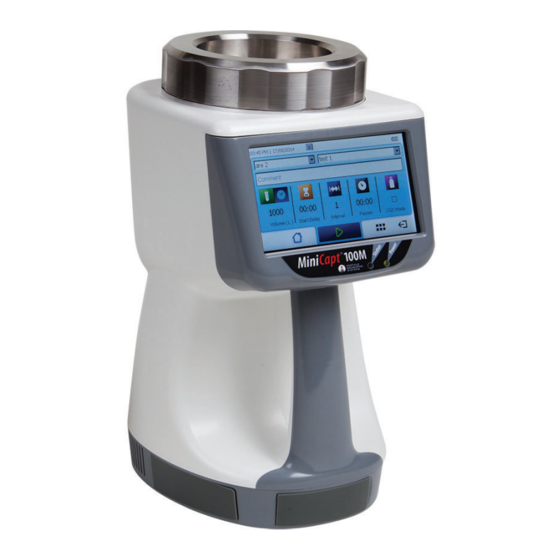
Chapter 1 Introduction ® The MiniCapt Mobile Microbial Air Sampler is a portable biological sample collection ® instrument that, when paired with the BioCapt Impactor sampler head, enables efficient biological sample collection. Airflow into the sampler head is controlled by a mass flow volumetric controller which ensures an operating flowrate of 25 LPM, 50 LPM or 100 LPM as per model specs. -
Page 23: Physical Description
Chapter 1 : Introduction Physical Description Physical Description Front Touchscreen • The touchscreen is located on the top of the MiniCapt Mobile chassis. • The touchscreen is backlit when the unit is powered on. LEDs Two LEDs are located below the touchscreen: •... -
Page 24: Local Power Supply And Charge-Battery Connector
Physical Description Chapter 1 : Introduction Local Power Supply and Charge-Battery Connector Power can be provided through the internal battery pack or the external AC to DC power supply which requires 100 - 240 V, 50/60 Hz AC power to produce the 18 VDC to power the unit. -
Page 25: Compressed Gas Connections And External Alarm
Chapter 1 : Introduction Physical Description Compressed Gas Connections and External Alarm The Compressed Gas Port and the Compressed Gas Solenoid Connector towards the base of the MiniCapt Mobile chassis allows connections to the Compressed Gas Kit (see Figure 1-4). The compressed gas solenoid connector can also be used to activate an external alarm or any 12 VDC device when the alarm activates. -
Page 26: General Characteristics
General Characteristics Chapter 1 : Introduction General Characteristics The MiniCapt Mobile Microbial Air Sampler makes it possible to pre-set sampling programs that can be activated from the touchscreen or via Modbus. The data saved from previous samplings are stored in memory, which can then: •... -
Page 27: Flowrate Monitoring Alarm
Chapter 1 : Introduction Warning and Alarm Systems Flowrate Monitoring Alarm The system checks to see if the difference between the working flow and the ideal flow (25 LPM, 50 LPM or 100 LPM) is within tolerance. At 20% difference, the instrument will turn off and not continue to sample. -
Page 28: Configuration
Configuration Chapter 1 : Introduction Configuration The MiniCapt Mobile requires configuration of the following operating parameters for sampling: • Choice of sampling mode (Time or Volume) • (Time mode) Sampling duration • 25 LPM: from 1 to 400 minutes • 50 LPM: from 1 to 200 minutes •... -
Page 29: Specifications
Chapter 1 : Introduction Specifications Specifications Table 1-1 MiniCapt Mobile Microbial Air Sampler Specifications 100M Sampling flowrate 25 Liters/minute 50 Liters/minute 100 Liters/minute 12 hours 7 hours 6 hours Battery (Lithium ion) Power 18 VDC, 3.9 A Battery: Rechargeable Lithium Ion battery pack Nominal Voltage: 14.8 VDC Capacity: 6400 mAh... - Page 30 Specifications Chapter 1 : Introduction Table 1-1 MiniCapt Mobile Microbial Air Sampler Specifications 100M Sampler Head Materials AISI 316L Stainless Steel Number of inlets 20 (precision-cut slits) Type 25/50 LPM and 100 LPM Accessories Isolator Kit, including the Isolator Stand and Impactor (no lid, clamp and gasket) P/N 90790043 P/N 90790043...
- Page 31 Chapter 1 : Introduction Specifications Table 1-1 MiniCapt Mobile Microbial Air Sampler Specifications 100M Remote Sampling Top Adapter with 3/4-in Tri-clamp Connection to BioCapt or BioCapt Single-Use P/N 90790048 NOTE: BioCapt or BioCapt Single Use not included. MiniCapt Mobile Spare Impactor Head P/N 1000019036 P/N 1000019036...
- Page 32 Specifications Chapter 1 : Introduction Table 1-1 MiniCapt Mobile Microbial Air Sampler Specifications 100M MiniCapt Power Supply/ Battery Charger P/N 1000019008 MiniCapt Lithium Battery Pack P/N 1000019006 Thermal Printer Kit P/N 90790070 Thermal Paper 1000000975 MiniCapt® Mobile Operations Manual 1-11...
- Page 33 Chapter 1 : Introduction Specifications Table 1-1 MiniCapt Mobile Microbial Air Sampler Specifications 100M Mounting Base Kit P/N 90790072 Barcode Reader P/N 90790071 Spare Red Silicone Rubber O-ring P/N 1000021241 Spare Impactor Head Lid Cover P/N 1000019051 MiniCapt IQ/OQ Validation P/N 1000021474 Protocol DataAnalyst Software...
-
Page 34: Chapter 2: Unpacking And Installation
Chapter 2 Unpacking and Installation Unpacking Instructions Inspecting for Any Shipping Damage Before you begin unpacking the MiniCapt Mobile Microbial Air Sampler, perform a visual inspection to see if the shipping container was damaged during shipping. If the shipping container is damaged, STOP unpacking and notify the shipper and Particle Measuring Systems at 1-877-475-3317, or email to support@pmeasuring.com. -
Page 35: Accessories
Chapter 2 : Unpacking and Installation Unpacking Instructions Table 2-1 Sample Packing List Item Quantity MiniCapt Mobile Microbial Air Sampler Impactor Sampler Head Lithium Ion Battery Pack Power Supply Refer to the actual Packing List enclosed with your shipment. Accessories If accessories are purchased, the following items may have been shipped. -
Page 36: Items You Need To Provide
Items you Need to Provide Chapter 2 : Unpacking and Installation Items you Need to Provide If the following items were not included, you will need to provide: • Tri-clamp • Tri-clamp gasket ¾ • Tri-clamp to barb fitting ” ½... -
Page 37: Select A Location
Chapter 2 : Unpacking and Installation Installation Select a Location When choosing the location for the MiniCapt Mobile Microbial Air Sampler(s), consider the following to improve the utility of the unit. • Sample Point Position the MiniCapt to ensure that the sampler head is pointed toward the airflow. -
Page 38: Install The Battery Pack
Installation Chapter 2 : Unpacking and Installation Install the Battery Pack The battery pack will be installed inside the base of the MiniCapt Mobile Microbial Air Sampler (see Figure 2-1 and Figure 2-2). Figure 2-1 Bottom of the MiniCapt Mobile Figure 2-2 Battery chamber with the cover Microbial Air Sampler removed... -
Page 39: Connect The Power Supply
Chapter 2 : Unpacking and Installation Installation Connect the Power Supply WARNING Ensure that the external AC to DC power supply has a proper earth ground supply cord. >> To connect the power supply: 1. Plug the power supply cord into Mains power. 2. -
Page 40: Power Up The Minicapt
Installation Chapter 2 : Unpacking and Installation Power Up the MiniCapt >> To power the MiniCapt ON: 1. Be sure you have installed the battery as described on page 2-5. 2. Be sure you have connected the power supply cord to mains power and to the MiniCapt as described above. -
Page 41: Charge The Battery
Chapter 2 : Unpacking and Installation Installation Charge the Battery It is recommended to charge the unit for at least 4 hours before the first use. The system operates off the battery for normal operations and will charge the battery when connected to main power through the AC/DC power supply. -
Page 42: Adjust The Plate Holder Diameter
Installation Chapter 2 : Unpacking and Installation Adjust the Plate Holder Diameter If the agar plate you intend to use does not fit inside the plate holder brackets, you can adjust the brackets in the plate holder to increase or decrease its diameter. The MiniCapt Mobile can be used with an agar plate having an external diameter between 86 and 92 mm. -
Page 43: Figure 2-5 Sampler Head On Minicapt
Chapter 2 : Unpacking and Installation Installation Sampler head Plate holder Sampler head (upside down) Figure 2-5 Sampler head on Figure 2-6 Sampler head off Figure 2-7 Sampler head MiniCapt of the MiniCapt removed 2. Remove the plate holder by rotating it counterclockwise until it comes off. Figure 2-8 Rotate plate holder counterclockwise to remove it 3. -
Page 44: Figure 2-9 Plate Holder Removed
Installation Chapter 2 : Unpacking and Installation Plate Holder (upside down) Figure 2-9 Plate holder removed Socket head cap Bracket Figure 2-10 Plate holder bracket socket head cap screws MiniCapt® Mobile Operations Manual 2-11... -
Page 45: Figure 2-11 Outer (Left) And Inner (Right) Set Of Bracket Holes
Chapter 2 : Unpacking and Installation Installation 4. Depending on the size of your Petri plate, you will need to use a 1.5 mm hex driver to either: • Loosen the screws to allow each bracket limited movement across the plate holder, OR •... - Page 46 Installation Chapter 2 : Unpacking and Installation 6. Center the dish with respect to the circles etched into the plate holder (see Figure 2-12) and move the brackets to hold the dish in that location. If the MiniCapt Mobile will be used to sample in the upright position (not horizontally), ensure the brackets allow the plate to lay flat against the plate holder.
-
Page 47: Adjust The Plate Height In The Plate Holder
Chapter 2 : Unpacking and Installation Installation Adjust the Plate Height in the Plate Holder To ensure the MiniCapt Mobile operates at its optimal performance, adjust the plate holder to ensure the agar plate is in the proper placement. The MiniCapt Mobile can be used with any agar plate having the following dimensions: •... -
Page 48: Figure 2-16 Locking Pin Of The Adjustable Plate
Installation Chapter 2 : Unpacking and Installation 2. If you are using an instrument manufactured prior to January 2016, skip this step: • Unlock the adjustable plate by rotating the locking pin clockwise. Figure 2-16 Locking pin of the adjustable plate 3. -
Page 49: Lock The Plate Holder
Chapter 2 : Unpacking and Installation Installation Figure 2-18 Rotate plate holder counterclockwise to raise it 8. Once contact is made, it is essential to lower the plate holder 5 clicks (0.5mm): a. Remove the agar plate. b. Rotate the plate holder clockwise (see Figure 2-19). Figure 2-19 Rotate plate holder clockwise to lower it 9. -
Page 50: Chapter 3: Display
Chapter 3 Display The touchscreen on the MiniCapt Mobile Microbial Air Sampler is used to configure the instrument and create and run sampling recipes. The fields and buttons on the Home screen and on the configuration screens are described in detail in this chapter. Home Screen When the instrument is first turned on, the Home screen appears (see Figure 3-1). -
Page 51: Chapter 3: Display
Chapter 3 : Display Home Screen Table 3-1 Fields on the Home screen Field Description Area Select the name of the sampling area in which the instrument is being list field used. If no area names have been defined, select the blank and type in a name for the area. -
Page 52: Table 3-3 Buttons On The Home Screen
Home Screen Chapter 3 : Display Table 3-2 Parameters fields and check box on the Home screen (Continued) Button Description Intervals Displays the current setting for the number of samples in a field single run. • From 1 to 1000 Touch on the value to enter a different value. -
Page 53: Features Menu Screen
Chapter 3 : Display Features Menu Screen Features Menu Screen The Features Menu screen (see Figure 3-4) has buttons for accessing the screens you will use to define configurations for the MiniCapt Mobile Microbial Air Sampler. Menu buttons Navigation buttons Figure 3-2 MiniCapt Features Menu screen The buttons on the Features Menu screen are described in Table 3-4. - Page 54 Features Menu Screen Chapter 3 : Display Table 3-4 Buttons on the Features Menu screen (Continued) Button Description Setup Touch to display the Setup Menu screen where you can access the button configuration screens for: • Alarm Comments See Chapter 8 Warnings and Alarms Setup, Alarm Comments on page 8-6.
-
Page 55: Select The Display Language
Chapter 3 : Display Select the Display Language Select the Display Language The MiniCapt screens can be displayed in any of the following languages: • Chinese (Simplified) • German • Chinese (Traditional) • Japanese • English • Korean • French •... -
Page 56: Figure 3-5 Setup Submenu Screen
Select the Display Language Chapter 3 : Display 2. Touch the Setup button on the Features Menu screen. The Setup Submenu appears (see Figure 3-5). Next page Figure 3-5 Setup Submenu screen 3. Touch the Next Page button on the Setup Submenu screen (see Figure 3-5).... -
Page 57: Figure 3-8 Language Screen
Chapter 3 : Display Select the Display Language Figure 3-7 Setup Submenu screen, page 3 5. Touch the Language button on page 3 of the Setup Submenu screen (see Figure 3-7). The Language screen appears (see Figure 3-8). Figure 3-8 Language screen 6. -
Page 58: Software Update
Software Update Chapter 3 : Display Software Update The About screen displays the software version currently installed (see About Screen on page 3-14). >> To update software in the MiniCapt Mobile Microbial Air Sampler: 1. Prepare an external USB drive with the software program on it. 2. -
Page 59: Figure 3-11 Features Menu Screen
Chapter 3 : Display Software Update Figure 3-11 Features Menu screen a. Touch the Setup button on the Features Menu screen (see Figure 3-11). The Setup Submenu appears (see Figure 3-12). Next page Figure 3-12 Setup Submenu screen 4. Touch the Next Page button on the Setup Submenu screen (see Figure 3-12).... -
Page 60: Figure 3-14 Software Update Screen
Software Update Chapter 3 : Display Figure 3-13 Setup Submenu screen, page 2 5. Touch the Software Update button on Page 2 of the Setup Submenu screen (see Figure 3-13 on page 3-11). The Software Update screen displays (see Figure 3-14). Figure 3-14 Software Update screen 6. -
Page 61: Figure 3-15 Update Software Screen
Chapter 3 : Display Software Update Figure 3-15 Update Software screen 7. In the Update Software screen, touch the software update file you want to run. The file choice appears selected (see Figure 3-16 on page 3-12). Figure 3-16 Update Software screen with a file selected 8. -
Page 62: Figure 3-18 Hourglass Symbol In Update Software Screen While Running Update
Software Update Chapter 3 : Display 9. Touch the Checkmark button in the Update Confirmation screen to begin the software update. The hourglass symbol spins during the update process (see Figure 3-18). 10. When the hourglass symbol disappears, the MiniCapt will automatically reboot. -
Page 63: About Screen
Chapter 3 : Display About Screen About Screen The About screen for the MiniCapt Mobile Microbial Air Sampler displays information about the software version currently installed. >> To view the About screen: 1. On the Home screen, touch the Features Menu button (see Figure 3-3). The Features Menu screen appears (see Figure 3-4). -
Page 64: Figure 3-21 Setup Submenu Screen
About Screen Chapter 3 : Display Next page Figure 3-21 Setup Submenu screen 3. Touch the Next Page button on the Setup Submenu screen (see Figure 3-21). Page 2 of the Setup Submenu screen displays (see Figure 3-22). Next page Figure 3-22 Setup Submenu screen, page 2 4. -
Page 65: Figure 3-24 About Screen Showing Software Version Number
Chapter 3 : Display About Screen Figure 3-23 Setup Submenu screen, page 3 5. Touch the About button on page 3 of the Setup Submenu screen (see Figure 3-23 on page 3-16). The About screen appears (see Figure 3-24). Figure 3-24 About screen showing software version number Touch the Features Menu button to return to the Features Menu screen.... -
Page 66: Chapter 4: Sampling
Chapter 4 Sampling The basic steps for sampling with the MiniCapt Mobile Microbial Air Sampler are described in this chapter. What You Need to Perform a Sampling >> To run a sample you will need the following items: • The MiniCapt installed as described in Chapter 2 Unpacking and Installation, on page 2-3. -
Page 67: Load The Agar Plate
Chapter 4 : Sampling Load the Agar Plate Load the Agar Plate >> To load an agar plate into the MiniCapt: TIP: Follow aseptic technique to load the agar plate into the MiniCapt. 1. Remove the sampler head (see Figure 4-2). Sampler Head Figure 4-1 Sampler head on MiniCapt... -
Page 68: Figure 4-3 Plate Holder Exposed
Load the Agar Plate Chapter 4 : Sampling Figure 4-3 Plate holder exposed 2. Place the agar plate on the plate holder (see Figure 4-4). Figure 4-4 Agar plate on the plate holder with agar plate lid still in place 3. -
Page 69: Figure 4-6 Power Button And Power Connector Port
Chapter 4 : Sampling Load the Agar Plate Power Button Figure 4-6 Power button and Power Connector port 6. When the MiniCapt is first turned on, the Home screen appears (see Figure 4-7). Figure 4-7 Home screen (Time view) 7. In the Area field at the top left of the Home screen, touch the down arrow button to display the list of available areas (see Figure 4-8). -
Page 70: Figure 4-9 Home Screen Showing The Location Field's List
Load the Agar Plate Chapter 4 : Sampling 10. Touch the location you want to use. Figure 4-9 Home screen showing the Location field’s list 11. If you want to enter notes about the sampling run, touch the Comment field to display the Keyboard screen.... - Page 71 Chapter 4 : Sampling Load the Agar Plate This page is intentionally left blank. MiniCapt® Mobile Operations Manual...
-
Page 72: Chapter 5: Recipes
Chapter 5 Recipes A recipe defines how you want to perform a sampling. That is, a recipe contains instructions such as where the sampling is taking place, when to begin a sampling, how long to sample, and so on. This chapter describes how to set up a recipe, how to modify a recipe, and how to delete a recipe for the MiniCapt Mobile Microbial Air Sampler. -
Page 73: Figure 5-2 Features Menu Screen
Chapter 5 : Recipes View the Recipe List Screen Figure 5-2 Features Menu screen 2. Touch the Recipe button on the Features Menu screen. The Recipes List screen appears (see Figure 5-3). Figure 5-3 Recipes List screen MiniCapt® Mobile Operations Manual... -
Page 74: Set Up A New Recipe
Set Up a New Recipe Chapter 5 : Recipes Set Up a New Recipe >> To define a new recipe: 1. View the Recipes List screen as described in View the Recipe List Screen on page 5-1. • If no recipes definitions exist, the Recipes List screen appears with no recipes in the list (see Figure 5-4). -
Page 75: Figure 5-6 Keyboard Screen For Entering A Recipe Name
Chapter 5 : Recipes Set Up a New Recipe Figure 5-6 Keyboard screen for entering a recipe name 3. Use the keyboard to enter a name for the recipe (maximum 16 characters): a. Touch each letter in the name to spell out the recipe’s name. b. -
Page 76: Figure 5-8 New Recipe Screen Showing Volume Buttons And Fields
Set Up a New Recipe Chapter 5 : Recipes 4. In the New Recipe screen, touch the button for the sampling mode you want to use for the recipe: • Time mode Figure 5-7 shows the buttons for the Time mode.) –... -
Page 77: Modify A Recipe
Chapter 5 : Recipes Modify a Recipe • The Volume mode fields are: • Volume field • Start Delay field • Interval field • Pauses field • CGS Mode check box 6. Touch the Save button in the New Recipe screen to save the recipe.... -
Page 78: Figure 5-10 Modify Recipe Screen
Modify a Recipe Chapter 5 : Recipes Figure 5-10 Modify Recipe screen 4. Modify values as needed: • The Time mode fields and check box are: • Time field • Start Delay field • Interval field • Pauses field • CGS Mode check box •... -
Page 79: Delete A Recipe
Chapter 5 : Recipes Delete a Recipe Delete a Recipe A recipe’s definition can be deleted. >> To delete a recipe: 1. View the Recipes List screen as described in View the Recipe List Screen on page 5-1. 2. In the Recipes List screen, touch the recipe you want to delete to highlight the recipe. -
Page 80: Figure 5-13 Delete Message: Are You Sure You Want To Delete Recipe
Delete a Recipe Chapter 5 : Recipes Figure 5-13 Delete message: Are you sure you want to delete recipe? 5. Touch the GREEN checkmark button in the Delete message. The recipe is deleted. MiniCapt® Mobile Operations Manual... - Page 81 Chapter 5 : Recipes Delete a Recipe This page is intentionally left blank. 5-10 MiniCapt® Mobile Operations Manual...
-
Page 82: Chapter 6: Locations And Areas
Chapter 6 Locations and Areas Sampling runs on the MiniCapt Mobile Microbial Air Sampler require the following information: • Area • Location • Recipe This chapter describes how to set up a definitions for locations and area. Locations and Areas for Sampling A physical location and an area in the plant can be associated with a recipe to use for a sampling run. -
Page 83: View The Locations List Screen
Chapter 6 : Locations and Areas View the Locations List Screen View the Locations List Screen >> To view the Locations List Screen: 1. On the Home screen, touch the Features Menu button (see Figure 6-1). The Features Menu screen appears (see Figure 6-2). Figure 6-1 Home screen Figure 6-2 Features Menu screen 2. -
Page 84: Add A Location And An Area, And Associate With A Recipe
Add a Location and an Area, and Associate with a Recipe Chapter 6 : Locations and Areas Add a Location Figure 6-3 Locations List screen. Add a Location and an Area, and Associate with a Recipe >> To define a location and an area: 1. -
Page 85: Figure 6-5 Location Name Keyboard Screen For Entering A Location Name
Chapter 6 : Locations and Areas Add a Location and an Area, and Associate with a Recipe Figure 6-5 Location Name Keyboard screen for entering a Location name 4. Use the keyboard to enter a name for the location (maximum 16 characters): a. -
Page 86: Figure 6-7 Area Name Keyboard Screen For Entering An Area Name
Add a Location and an Area, and Associate with a Recipe Chapter 6 : Locations and Areas Figure 6-7 Area Name Keyboard screen for entering an area name 6. Use the keyboard to enter a name for the area: a. Touch each letter in the name to spell out the area’s name. b. -
Page 87: Modify A Location Definition
Chapter 6 : Locations and Areas Modify a Location Definition Modify a Location Definition A location definition can be modified or deleted. >> To modify a location definition: 1. View the Locations List screen as described in View the Locations List Screen on page 6-2. -
Page 88: Figure 6-11 Modify Location Screen
Modify a Location Definition Chapter 6 : Locations and Areas Modify Area Figure 6-11 Modify Location screen 4. In the Area field at the top of the Modify Location screen, touch the down arrow button to display the list of areas already defined, then touch the desired area from the drop down list. -
Page 89: Figure 6-13 Keyboard Screen For Entering A Location Name
Chapter 6 : Locations and Areas Modify a Location Definition 5. To modify the location currently defined, touch the Location field in the middle of the Modify Location screen to display the Keyboard screen (see Figure 6-13 on page 6-8). Figure 6-13 Keyboard screen for entering a location name 6. -
Page 90: Delete A Location Definition
Delete a Location Definition Chapter 6 : Locations and Areas Delete a Location Definition >> To Delete a location definition: 1. View the Locations List screen as described in View the Locations List Screen on page 6-2. Modify a Location Figure 6-14 Locations List screen. -
Page 91: Figure 6-16 Delete Message: Are You Sure You Want To Delete Location
Chapter 6 : Locations and Areas Delete a Location Definition Figure 6-16 Delete message: Are you sure you want to delete location? 5. Touch the GREEN checkmark button in the Delete message. • The location is deleted. • The Location List screen appears. 6-10 MiniCapt®... -
Page 92: Chapter 7: Reports
Chapter 7 Reports This chapter describes how to view and manage report records for the MiniCapt Mobile Microbial Air Sampler. You can: • View a report record, which is a record of events for a sampling run. • Search for a specific report record. •... -
Page 93: Figure 7-2 Features Menu Screen
Chapter 7 : Reports View the Reports List Screen Figure 7-2 Features Menu screen 2. Touch the Data button on the Features Menu screen. The Data Submenu screen displays (see Figure 7-3). Figure 7-3 Data Submenu screen MiniCapt® Mobile Operations Manual... -
Page 94: Figure 7-4 Reports List Screen
View the Reports List Screen Chapter 7 : Reports 3. In the Data Submenu screen, touch the Report Records button. The Reports List screen appears (see Figure 7-4). View Report Search Delete Report Export Report Figure 7-4 Reports List screen MiniCapt®... -
Page 95: View A Report
Chapter 7 : Reports View a Report View a Report >> To view a report record for a sampling run: 1. Open the Reports List screen as described in Export a report record. on page 7-1. 2. In the Reports List screen, use one of the following methods to view a report: METHOD 1: a. -
Page 96: Delete A Report Record
Delete a Report Record Chapter 7 : Reports Figure 7-6 Report Record screen Delete a Report Record >> To delete a sampling run’s report record: 1. Open the Reports List screen as described in View the Reports List Screen on page 7-1. -
Page 97: Export A Report Record
Chapter 7 : Reports Export a Report Record Export a Report Record >> To export a sampling run’s report record: 1. Insert an external USB drive into the USB port on the front of the MiniCapt base (see Figure 7-8). Figure 7-8 USB port on the front of the MiniCapt base 2. -
Page 98: Figure 7-10 Export Button, Reports List Screen
Export a Report Record Chapter 7 : Reports 4. Touch the Export button on the Reports List screen (Figure 7-10). Figure 7-10 Export button, Reports List screen 5. When selected, the report is highlighted and marked. Press the green checkmark button (Figure 7-11). Figure 7-11 Reports Selection screen MiniCapt®... -
Page 99: Figure 7-12 Example "Test" File Export
Chapter 7 : Reports Export a Report Record 6. Enter a file name and press the Export Report button. The report is copied to the external USB drive. A sample HTML Report is displayed in Appendix F, Sample HTML Reports Export Report Figure 7-12 Example “Test”... -
Page 100: Chapter 8: Warnings And Alarms Setup
Chapter 8 Warnings and Alarms Setup This chapter describes configuration of warnings and alarms for the MiniCapt Mobile Microbial Air Sampler. Warnings: A warning will occur if the flow is ± 5% of the calibrated flowrate (up to ±20%). The warning will be visual on the screen as well as audible if sound is configured. See Audio for Warnings and Alarms on page 8-10. -
Page 101: Figure 8-2 Features Menu Screen
Chapter 8 : Warnings and Alarms Setup View the Warnings and Alarms List Screen Figure 8-2 Features Menu screen 2. Touch the Data button on the Features Menu screen. The Data screen displays (see Figure 8-3). Figure 8-3 Warning and Alarms button, Data Submenu screen 3. -
Page 102: Export Warning And Alarms Reports
Export Warning and Alarms Reports Chapter 8 : Warnings and Alarms Setup 4. Select a report and press the View button to view the report. View Export Figure 8-4 Warnings and Alarms List screen Export Warning and Alarms Reports >> To export a sample’s Warning and Alarms: 1. -
Page 103: Figure 8-6 Warning And Alarms Button, Data Submenu Screen
Chapter 8 : Warnings and Alarms Setup Export Warning and Alarms Reports Figure 8-6 Warning and Alarms button, Data Submenu screen 4. From the previous step, you should be on the Warning and Alarms List screen (see Figure 8-7). Touch the Export button. Figure 8-7 Export button, Warning and Alarms List screen 5. -
Page 104: Figure 8-8 Warning And Alarms Selection Screen
Export Warning and Alarms Reports Chapter 8 : Warnings and Alarms Setup 6. Press the green checkmark button when finished selecting reports. Figure 8-8 Warning and Alarms Selection screen 7. Enter a file name and press the Export Report button. The report is copied to the external USB drive. -
Page 105: Alarm Comments
Chapter 8 : Warnings and Alarms Setup Alarm Comments Alarm Comments You can pre-program up to 20 different comments that describe alarm conditions. Comment definitions display in the Comment dropdown list of the Home screen. Then, if an alarm occurs during a sampling run, you must select the comment that applies so that the comment for the alarm related to the event is saved with the record for the sampling run. -
Page 106: Figure 8-12 Setup Submenu Screen
Alarm Comments Chapter 8 : Warnings and Alarms Setup Alarm Comments Figure 8-12 Setup Submenu screen 3. Touch the Alarm Comments button on the Setup Submenu screen. The Alarm Comments screen displays (see Figure 8-13). Figure 8-13 Alarm Comments List screen MiniCapt®... -
Page 107: Modify An Alarm Comment
Chapter 8 : Warnings and Alarms Setup Modify an Alarm Comment Modify an Alarm Comment >> To modify and alarm’s comment: 1. Open the Alarm Comments List screen as described in step 3 of the To view the Alarm Comments screen: procedure. Modify Comment Figure 8-14 Alarm Comments List screen... -
Page 108: Figure 8-16 Alarm Comments List Screen With A Comment Defined
Modify an Alarm Comment Chapter 8 : Warnings and Alarms Setup 4. Use the keyboard to enter a comment to link to the alarm (maximum 64 characters): a. Touch each letter in the name to spell out the text for the comment. b. -
Page 109: Audio For Warnings And Alarms
Chapter 8 : Warnings and Alarms Setup Audio for Warnings and Alarms Audio for Warnings and Alarms The Sounds screen is used to link audible sounds to the following events: • Warning Notification • Alarm Notification • End of Sample Notification •... -
Page 110: Figure 8-19 Setup Submenu Screen
Audio for Warnings and Alarms Chapter 8 : Warnings and Alarms Setup 2. Touch the Setup button on the Features Menu screen. The Setup Submenu appears (see Figure 8-19 on page 8-11). Next Page Figure 8-19 Setup Submenu screen 3. Touch the Next Page button on the Setup Submenu screen (see Figure 8-19).... -
Page 111: Figure 8-21 Sounds Screen Showing All Events Check Marked For Sound
Chapter 8 : Warnings and Alarms Setup Audio for Warnings and Alarms Figure 8-21 Sounds screen showing all events check marked for sound 5. If you want to turn off sound for an event listed in the Sounds screen, touch that event’s check box to remove the checkmark (see Figure 8-22). -
Page 112: Figure 8-23 Connection Diagram For Auxiliary External Alarm Connection
Audio for Warnings and Alarms Chapter 8 : Warnings and Alarms Setup 7. The external alarm activation is driven using the compressed gas auxiliary port. The auxiliary port powers any external device working at a 12VDC with a maximum current of 10W (800mA).The external alarm connection requires the connector product number (PN) 1000019268.... - Page 113 Chapter 8 : Warnings and Alarms Setup Audio for Warnings and Alarms This page is intentionally left blank. 8-14 MiniCapt® Mobile Operations Manual...
-
Page 114: Chapter 9: Time And Date Setup
Chapter 9 Time and Date Setup This chapter describes how to configure the current time and date for the MiniCapt Mobile Microbial Air Sampler. View the Time and Date Screen >> To view the Time and Date screen: 1. On the Home screen, touch the Features Menu button (see Figure 9-1).... -
Page 115: Figure 9-2 Features Menu Screen
Chapter 9 : Time and Date Setup View the Time and Date Screen Figure 9-2 Features Menu screen 2. Touch the Setup button on the Features Menu screen. The Setup Submenu screen displays (see Figure 9-3 on page 9-2). Figure 9-3 Setup Submenu screen 3. -
Page 116: Set The Time And Date
Set the Time and Date Chapter 9 : Time and Date Setup Figure 9-4 Time and Date screen Set the Time and Date The date can be entered in three different formats • Day, month, year • Month, day, year •... -
Page 117: Figure 9-6 Time And Date Screen Calendar For Setting The Current Date
Chapter 9 : Time and Date Setup Set the Time and Date 2. In the top date field of the SET DATE pane in the Time and Date screen, touch the list button to display a calendar (see Figure 9-6). Figure 9-6 Time and Date screen calendar for setting the current date. - Page 118 Set the Time and Date Chapter 9 : Time and Date Setup 8. In the top field of the SET TIME pane in the Time and Date screen, touch the minutes, then touch the left arrow or the right arrow to scroll to the current minutes.
- Page 119 Chapter 9 : Time and Date Setup Set the Time and Date This page is intentionally left blank. MiniCapt® Mobile Operations Manual...
-
Page 120: Chapter 10: Network Communication
Chapter 10 Network Communication This chapter describes how to set the IP address for MiniCapt Mobile Microbial Air Sampler IP address for communicating with the local area network. View the Network Screen >> To view the Network screen: 1 On the Home screen, touch the Features Menu button (see Figure 10-1).... -
Page 121: Figure 10-3 Setup Submenu Screen
Chapter 10 Network Communication View the Network Screen 2 Touch the Setup button on the Features Menu screen. The Setup Submenu screen displays (see Figure 10-3 on page 10-2). Network Figure 10-3 Setup Submenu screen 3 Touch the Network button on the Setup Submenu screen. The Network screen displays (see Figure 10-4). -
Page 122: Set The Ip Address For The Minicapt
Set the IP Address for the MiniCapt Chapter 10 Network Communication Set the IP Address for the MiniCapt >> To set the IP address for the MiniCapt: 1 View the Network screen as described in View the Network Screen on page 10-1. Figure 10-5 Network screen 2 There are 4 positions in the IP Address field.... - Page 123 Chapter 10 Network Communication Set the IP Address for the MiniCapt 5 Use the same method to set the values for the Subnet Mask and the Gateway fields. 6 Touch the Features Menu button to return to the Features Menu screen. –OR–...
-
Page 124: Chapter 11: Import
Chapter 11 Import This chapter describes how to import certain types of data from an external USB device into the MiniCapt Mobile Microbial Air Sampler. The data types that can be imported include: • User and access details • Location definitions •... -
Page 125: Figure 11-2 Features Menu Screen
Chapter 11 : Import View the Import Screen Figure 11-2 Features Menu screen 2. Touch the Setup button on the Features Menu screen. The Setup Submenu screen displays (see Figure 11-3). Figure 11-3 Setup Submenu screen 3. Touch the Import button on the Setup Submenu screen. The Import screen displays (see Figure 11-4). -
Page 126: Import Data Into The Minicapt
Import Data into the MiniCapt Chapter 11 : Import Figure 11-4 Import screen Import Data into the MiniCapt >> To import data files previously exported from a MiniCapt: 1. Prepare an external USB drive with the files you want to import into the MiniCapt Mobile Microbial Air Sampler. -
Page 127: Figure 11-6 Import Screen
Chapter 11 : Import Import Data into the MiniCapt 4. Touch one of the following options for how to write the data files you are importing: • Delete all and import – Remove all existing files of the same type as those you are importing. -
Page 128: Figure 11-8 Import Successful Message Screen
Import Data into the MiniCapt Chapter 11 : Import 6. Touch the file you want to import to select it (see Figure 11-7). The file you selected appears in the FILENAME field in the USB FLASH DRIVE ‘Hard Disk’ screen. 7. - Page 129 Chapter 11 : Import Import Data into the MiniCapt This page is intentionally left blank. 11-6 MiniCapt® Mobile Operations Manual...
-
Page 130: Chapter 12: Units For Measurements
Chapter 12 Units for Measurements This chapter describes how to select the units of measurement and the decimal separator to be used by the MiniCapt Mobile Microbial Air Sampler. View the Units Screen >> To view the Units screen: 1. On the Home screen, touch the Features Menu button (see Figure 12-1).... -
Page 131: Figure 12-3 Setup Submenu Screen
Chapter 12 : Units for Measurements View the Units Screen 2. Touch the Setup button on the Features Menu screen. The Setup Submenu screen displays (see Figure 12-3 on page 12-2). Figure 12-3 Setup Submenu screen 3. Touch the Units button on the Setup Submenu screen. The Units screen displays (see Figure 12-4). -
Page 132: Set The Units For The Minicapt
Set the Units for the MiniCapt Chapter 12 : Units for Measurements Set the Units for the MiniCapt The Units screen is used to select the decimal separator and the volume unit. >> To set the units for the MiniCapt: 1. - Page 133 Chapter 12 : Units for Measurements Set the Units for the MiniCapt This page is intentionally left blank. 12-4 MiniCapt® Mobile Operations Manual...
-
Page 134: Chapter 13: Export
Chapter 13 Export This chapter describes how to export data from the MiniCapt Mobile Microbial Air Sampler to an external USB device. The types of data that can be exported include: • User and access details • Location definitions • Recipe definitions View the Export Screen >>... -
Page 135: Figure 13-2 Features Menu Screen
Chapter 13 : Export View the Export Screen Figure 13-2 Features Menu screen 2. Touch the Setup button on the Features Menu screen. The Setup Submenu screen displays (see Figure 13-3). Export Figure 13-3 Setup Submenu screen 13-2 MiniCapt® Mobile Operations Manual... -
Page 136: Figure 13-4 Export Screen
View the Export Screen Chapter 13 : Export 3. Touch the Export button on the Setup Submenu screen. The Export screen displays (see Figure 13-4). Figure 13-4 Export screen MiniCapt® Mobile Operations Manual 13-3... -
Page 137: Export Data From The Minicapt
Chapter 13 : Export Export Data from the MiniCapt Export Data from the MiniCapt >> To export data from the MiniCapt: 1. Insert an external USB drive into the USB port on the front of the MiniCapt base (see Figure 13-5). Figure 13-5 USB port on the front of the MiniCapt base 2. -
Page 138: Figure 13-7 Usb Flash Drive 'Hard Disk' Screen
Export Data from the MiniCapt Chapter 13 : Export 4. Touch the Export Now button in the Export screen to display the USB FLASH DRIVE ‘Hard Disk’ screen (see Figure 13-7 on page 13-5). Figure 13-7 USB FLASH DRIVE ‘Hard Disk’ screen 5. -
Page 139: Figure 13-9 Usb Flash Drive 'Hard Disk' Screen Showing An Export Filename Defined
Chapter 13 : Export Export Data from the MiniCapt Figure 13-9 USB FLASH DRIVE ‘Hard Disk’ screen showing an export filename defined 7. Touch the Export File button on the USB FLASH DRIVE ‘Hard Disk’ screen (see Figure 13-9). • The data items you selected are copied to the external USB drive. -
Page 140: Print Data From The Minicapt
Print Data from the MiniCapt Chapter 13 : Export Print Data from the MiniCapt Figure 13-11 USB port on the front of the MiniCapt base 1. Insert the USB end of the printer cable into the USB port on the front of the MiniCapt base (see Figure 13-5). - Page 141 Chapter 13 : Export Print Data from the MiniCapt This page is intentionally left blank. 13-8 MiniCapt® Mobile Operations Manual...
-
Page 142: Chapter 14: User Management
Chapter 14 User Management This chapter describes user management. Specifically, how to: • View the list of current users in the Users List screen (see below) • Add a user (see Add a User on page 14-3) • Delete a user (see Remove a User on page 14-7) Up to 50 users and passwords may be entered. -
Page 143: Figure 14-2 Features Menu Screen
Chapter 14 : User Management View the Users List Screen Figure 14-2 Features Menu screen 2. Touch the User button on the Features Menu screen. The Users List screen displays (see Figure 14-3). Figure 14-3 Users List screen 14-2 MiniCapt® Mobile Operations Manual... -
Page 144: Add A User
Add a User Chapter 14 : User Management Add a User >> To add a user: 1. View the Users List screen as described in View the Users List Screen on page 14-1. User Figure 14-4 Users List screen 2. Touch the Add User button in the Users List screen (see Figure 14-4) to display the New User screen shown in Figure 14-5. -
Page 145: Figure 14-6 Keyboard Screen For Entering Username
Chapter 14 : User Management Add a User Figure 14-6 Keyboard screen for entering username a. Use the keyboard to enter the username: • Touch the keys on the keyboard to define the username, maximum 16 characters. b. Touch the Done button in the keyboard screen. •... -
Page 146: Figure 14-7 Credentials Field List In The New User Screen
Add a User Chapter 14 : User Management 5. Touch the Retype Password field (3rd field) to display the Keyboard screen (see Figure 14-6). a. Use the keyboard to enter the user’s password again: b. Touch the Done button in the keyboard screen. •... -
Page 147: Modify A User
Chapter 14 : User Management Modify a User Modify a User >> To modify a user: 1. View the Users List screen as described in View the Users List Screen on page 14-1. 2. Touch the name of the user you want to work with to select it. Modify User Figure 14-9 Users List screen... -
Page 148: Remove A User
Remove a User Chapter 14 : User Management 4. Modify the fields as described in Add a User on page 14-3 to define: • username • password • credentials 5. Touch the Save User Changes button in the User screen. The Users List screen displays. -
Page 149: Figure 14-12 Delete User Confirmation Screen
Chapter 14 : User Management Remove a User Figure 14-12 Delete User Confirmation screen 4. Touch the GREEN checkmark button in the Delete User Confirmation message. • The user is deleted. • The Users List screen appears. 14-8 MiniCapt® Mobile Operations Manual... -
Page 150: User Management
User Management Chapter 14 : User Management User Management Follow this procedure to enable instrument security with the Enable Protection feature. >> To activate the Enable Protection feature: 1. View the Users List screen as described in View the Users List Screen on page 14-1. - Page 151 Chapter 14 : User Management User Management This page is intentionally left blank. 14-10 MiniCapt® Mobile Operations Manual...
-
Page 152: Chapter 15: System Status
Chapter 15 System Status This chapter describes how to view the status of the most recent MiniCapt Mobile Microbial Air Sampler sampling run in the System Status screen. View the System Status Screen >> To view the System Status screen: 1. -
Page 153: Figure 15-2 Features Menu Screen
Chapter 15 : System Status View the System Status Screen Figure 15-2 Features Menu screen a. Touch the Setup button on the Features Menu screen. The Setup Submenu appears (see Figure 15-3). Next Page Figure 15-3 Setup Submenu screen 2. Touch the Next Page button on the Setup Submenu screen (see Figure 15-3).... -
Page 154: Figure 15-5 System Status Screen
View the System Status Screen Chapter 15 : System Status Figure 15-4 Setup Submenu screen, page 2 3. Touch the System Status button on Page 2 of the Setup Submenu screen (see Figure 15-4). The System Status screen displays (see Figure 15-5 on page 15-3). Figure 15-5 System Status screen The components of the System Status screen are described in Table 15-1. - Page 155 Chapter 15 : System Status View the System Status Screen This page is intentionally left blank. 15-4 MiniCapt® Mobile Operations Manual...
-
Page 156: Chapter 16: Queue Size
Chapter 16 Queue Size The MiniCapt Mobile Microbial Air Sampler queue retains the data for up to 3,000 sampling runs. The records are retained in the queue until you clear the queue using the Queue Setting screen. This chapter describes how to set the queue size currently set for data records from sampling runs and how to clear the queue. -
Page 157: Figure 16-2 Features Menu Screen
Chapter 16 : Queue Size View the Queue Setting Screen Figure 16-2 Features Menu screen a. Touch the Setup button on the Features Menu screen. The Setup Submenu appears (see Figure 16-3 on page 16-2). Next Page Figure 16-3 Setup Submenu screen 2. -
Page 158: Figure 16-5 Queue Setting Screen
View the Queue Setting Screen Chapter 16 : Queue Size Queue Setting Figure 16-4 Setup Submenu screen, page 2 3. Touch the Queue Setting button on Page 2 of the Setup Submenu screen (see Figure 16-4). The Queue Setting screen displays (see Figure 16-5). Figure 16-5 Queue Setting screen The components of the Queue Setting screen are described in Table 16-1. -
Page 159: Change The Size Of The Queue
Chapter 16 : Queue Size Change the Size of the Queue Change the Size of the Queue >> To modify the queue size: 1. View the Queue Setting screen as described in View the Queue Setting Screen on page 16-1. 2. -
Page 160: Chapter 17: Calibration
Chapter 17 Calibration A MiniCapt Mobile Microbial Air Sampler touchscreen response is calibrated at the factory. After purchase, the MiniCapt’s touchscreen response should be calibrated at least annually. This chapter describes how to: • Set the frequency for calibration notifications: •... -
Page 161: Figure 17-1 Home Screen
Chapter 17 : Calibration View the Calibration Notification Screen Figure 17-1 Home screen Figure 17-2 Features Menu screen a. Touch the Setup button on the Features Menu screen. The Setup Submenu appears (see Figure 17-3 on page 17-2). Next Page Figure 17-3 Setup Submenu screen 17-2 MiniCapt®... -
Page 162: Figure 17-5 Calibration Notification Screen
View the Calibration Notification Screen Chapter 17 : Calibration 2. Touch the Next Page button on the Setup Submenu screen (see Figure 17-3). Page 2 of the Setup Submenu screen displays (see Figure 17-4). Figure 17-4 Setup Submenu screen, page 2 3. -
Page 163: Frequency Of Calibration Notification Reminders
Chapter 17 : Calibration Frequency of Calibration Notification Reminders Table 17-1 Components of the Calibration Notification screen Button Description Last Calibrated On Displays the date the MiniCapt was last calibrated. field Reminder Duration Touch an option button to set the trigger for the calibration options reminder notification to one of the following time periods: •... -
Page 164: View The Calibrate Screen
View the Calibrate Screen Chapter 17 : Calibration View the Calibrate Screen The MiniCapt’s touchscreen response is calibrated using the Calibrate screen. >> To view the Calibrate screen: 1. On the Home screen, press the Features Menu button (see Figure 17-2). The Features Menu screen appears (see Figure 17-3). -
Page 165: Figure 17-8 Setup Submenu Screen
Chapter 17 : Calibration View the Calibrate Screen Next Page Figure 17-8 Setup Submenu screen 2. Touch the Next Page button on the Setup Submenu screen (see Figure 17-8). Page 2 of the Setup Submenu screen displays (see Figure 17-9). Next Page Figure 17-9 Setup Submenu screen, page 2... -
Page 166: Figure 17-11 Calibrate Screen
View the Calibrate Screen Chapter 17 : Calibration Figure 17-10 Setup Submenu screen, page 3 4. Touch the Calibrate Screen button on Page 2 of the Setup Submenu screen (see Figure 17-10 on page 17-7). The Calibrate screen displays (see Figure 17-11). Figure 17-11 Calibrate screen MiniCapt®... -
Page 167: Calibrate The Touchscreen's Response To Touch
Chapter 17 : Calibration Calibrate the Touchscreen’s Response to Touch Calibrate the Touchscreen’s Response to Touch The MiniCapt’s touchscreen response is calibrated using the Calibrate screen. >> To calibrate the touchscreen’s response to touch: 1. View the Calibrate screen as described in View the Calibrate Screen on page 17-5. -
Page 168: Chapter 18: Accessories
Chapter 18 Accessories Accessories for the MiniCapt Mobile Microbial Air Sampler are available in the following kits: • Isolator Monitoring Kit (see Isolator Monitoring Kit on page 18-2). • Remote Sampling ISP Kit (see Remote ISP Sampling Kit on page 18-3). •... -
Page 169: Isolator Monitoring Kit
Chapter 18 : Accessories Isolator Monitoring Kit Isolator Monitoring Kit The Isolator Monitoring Kit (see Figure 18-1 on page 18-2) can be used for sampling in an isolator. There are two Isolator Monitoring kits: • 25/50 LPM units • 100 LPM unit NOTE: For correct sampling, ensure the correct kit for required flowrate is used. -
Page 170: Remote Isp Sampling Kit
Remote ISP Sampling Kit Chapter 18 : Accessories 4. Connect the Impactor Tripod to the Remote Sampling Adaptor: a. Use a Tri-Clamp to attach one end of the tubing to the Remote Sampling Adaptor. b. Use a Tri-Clamp to attach the other end of the tubing to the Impactor Tripod. -
Page 171: Remote Connection To Biocapt
Chapter 18 : Accessories Remote Connection to BioCapt >> To install the Remote Sampling ISP Kit on the MiniCapt: 1. Follow steps 1 and 2 in on page 4-2 to Load the Agar Plate Load the Agar Plate install the agar plate. 2. -
Page 172: Figure 18-4 Biocapt Stainless Steel
Remote Connection to BioCapt Chapter 18 : Accessories 3. Place the Impactor at the suitable sampling point. 4. Connect the Impactor to the Remote Sampling Adaptor: a. Use a Tri-Clamp to attach one end of the tubing to the Remote Sampling Adaptor. -
Page 173: Remote Connection To Biocapt Single-Use
Chapter 18 : Accessories Remote Connection to BioCapt Remote Connection to BioCapt Single-Use The Remote Connection to BioCapt can be used to attach the MiniCapt Mobile Microbial Air Sampler to a Single-Use Impactor. The Remote Connection to BioCapt Single-Use may only be used with 25/50 LPM units. To install the Remote Connection to BioCapt Single-Use Kit on the MiniCapt: 1. -
Page 174: Chapter 19: Maintenance And Performance Checks
Chapter 19 Maintenance and Performance Checks There are no user-serviceable items the MiniCapt Mobile Microbial Air Sampler. Cleaning the Sampler Cleaning the BioCapt Impactor Head 1. This is made of AISI 316L Stainless steel and can be sterilized in an autoclave. 2. -
Page 175: Compatibility To Vaporous Hydrogen Peroxide (Vhp)
Chapter 19 : Maintenance and Performance Checks Compatibility to Vaporous Hydrogen Peroxide (VHP) The following chemicals have been shown to be acceptable for use with the MiniCapt Mobile Microbial Air Sampler: Table 19-1 Acceptable Cleaners for the MiniCapt Mobile Microbial Air Sampler Chemical ID Brand Name Isopropyl Alcohol IPA 70/30... -
Page 176: Cable Connectors
Cable Connectors Chapter 19 : Maintenance and Performance Checks Cable Connectors Occasionally a cable connector may be damaged through an accident. If a connector is damaged, be careful not to aggravate the problem by forcing a cable into a damaged connector. - Page 177 Chapter 19 : Maintenance and Performance Checks Performance Checks This page is intentionally left blank. 19-4 MiniCapt® Mobile Operations Manual...
-
Page 178: Chapter 20: Troubleshooting
Chapter 20 Troubleshooting Use this chapter to help troubleshoot issues with the MiniCapt Mobile Microbial Air Sampler, such as power issues, communication messages, errors and leaks. Troubleshooting Matrix Problem Symptoms Possible Cause No Power No lights Power supply not Check the seating of the power connected to a power supply cable in the unit. -
Page 179: Alarms And Warnings List
Chapter 20 : Troubleshooting Alarms and Warnings List Alarms and Warnings List Alarms and Warnings Area with same name already exist. Battery charge is below 10% Battery charge is below 5% BCLA Battery charge Low Alarm BCLW Battery charge Low Warning Cannot delete. - Page 180 Alarms and Warnings List Chapter 20 : Troubleshooting No device recognized. Pressure High Alarm Pressure High Warning Pressure Low Alarm Pressure Low Warning Recipe with same name already exist. The disk space is low._ The product supports to add 50 users only. The product supports to add 400 areas only.
-
Page 181: Air Flowrate Errors
Chapter 20 : Troubleshooting Air Flowrate Errors Air Flowrate Errors As a result of the performance check procedure (see on page 19-3 Performance Checks of Chapter 19 Maintenance and Performance Checks), the flowrate at the sampler’s inlet should be the following. •... -
Page 182: Appendix A Communications
Appendix A Communications Communications with the MiniCapt are available via Modbus TCP . The instrument presents a single TCP/IP Ethernet connection at port 502 using the standard Modbus protocol. Two specification documents were used in the development of the Modbus interface: •... -
Page 183: Input Registers
Appendix A : Communications Input Registers • Any registers accessed but not defined will generate an address error. • Spare coils/registers will “set” without error and always return a zero value. • Registers set with invalid data will return a function error. The map delineates three types of register assemblies: an individual 16 bit register Unary:... -
Page 184: Appendix A: Communications
Input Registers Appendix A : Communications 30001: This is a fixed value representing the version number of the Modbus map multiplied by 100. This version will change if/when the basic Modbus Map Version structure of the map and/or processing associated with the structure of the map is adjusted. -
Page 185: Table A-1 Input Register - Configuration
Appendix A : Communications Input Registers Table A-1 Input register – Configuration Input Registers Description (Configuration) Comment Notes 30001 unary Modbus Map Version Version 1.00 (Static 100) 30002 unary Sensor Firmware Version Encoded Firmware ver- sion 30003 unary Product Name: Char 00, 01 Product Name 30004 string... -
Page 186: Data Section
Input Registers Appendix A : Communications Data Section The Data section contains: • Calibration Date • Serial Number • Device Status • Device State • Number of data samples in queue • Sample Data information The Data section starts with what would have normally been considered configuration information - calibration date and serial number. -
Page 187: Table A-2 Input Register - Data Packet
Appendix A : Communications Input Registers Dual-register representation of data packet time stamp. Integer value (type 30216 – 30217: defined as time_t) representing start date/time in seconds since January 1, Time Stamp 1970. Dual-register representation of data packet sample interval processed in 30218 –... - Page 188 Input Registers Appendix A : Communications Table A-2 Input register – Data Packet (Continued) 30210 string Serial Number: Char 12, 13 Serial Number 30211 string Serial Number: Char 14, 15 Serial Number 30212 unary Device Status (high) Device Status Mask 30213 unary Device Status (low)
-
Page 189: Holding Registers
Appendix A : Communications Holding Registers Holding Registers Like the coils, spares are in place between the “standard” registers and those that are designated as specific/optional. There are no specific/optional coils defined for the MiniCapt. If the sample setting holding registers are sent while the unit is sampling, it will ignore the new settings until the next sample set is executed. -
Page 190: Coils
Coils Appendix A : Communications Coils Like the holding registers, spares are in place between the “standard” coils and those that are designated as specific/optional. There are no specific/optional coils defined for the MiniCapt. The data collection coil will enable/disable sampling. 00/01: Read: 1=Sampling Enabled, 0=Sampling Disabled. -
Page 191: Table A-4 Coils
Appendix A : Communications Coils Table A-4 Coils Coils Description (Coils) Comment Data Collection On/Off Sampling Control 00/01 Data Available Yes/No Data Available/Queue Control 00/02 Data Clear Toggle Data Queue Delete 00/03 Reset Sensor Toggle Reset control 00/04 Status LED: Green On/Off Status LED: Green Control 00/05... -
Page 192: Data Packet Processing
Data Packet Processing Appendix A : Communications Data Packet Processing The unit can provide real-time data or queued data or both. There is only one section of input registers assigned for data to handle this information. If the unit is setup to queue data then the data shown is the oldest data in the queue. The data available coil (00/02) will be set on a read if there is data in the queue. -
Page 193: Associated Values For Specific Registry Entries
Appendix A : Communications Associated Values for Specific Registry Entries Associated Values for Specific Registry Entries Table A-5 Associated values for specific registry entries 0x0001 Data Collection Matches the common coil settings Device Status Entries 0x0002 Data Available 0x0004 Data Clear 0x0008 Reset 0x0010... -
Page 194: Appendix B Report Examples
Appendix B Report Examples Example of Printed Reports The printed report is produced by the instrument when it is downloaded to a USB and sent to the printer or a request to download the serial buffer is made by a serial device. Example of Print in English MiniCapt®... -
Page 195: Appendix B: Report Examples
Appendix B : Report Examples Example of Printed Reports This page is intentionally left blank. MiniCapt® Mobile Operations Manual... -
Page 196: Appendix C 有毒或有害的物质和元素
Appendix C 有毒或有害的物质和元素 有毒或有害的物质和元素 Part Name 部件名称 铅 汞 镉 六价铬 多溴联苯 多溴联苯醚 (Pb) (Hg) (Cd) (Cr(VI)) (PBB) (PBDE) 电源供应 印刷电路装配 机械部件 电缆 机电 电池 O: 表示用于部件的所有同族物质中所含的有毒或有害物质低于 SJ/T11363-2006 规定的限 度要求。 X: 表示用于部件的至少一种同族物质中所含的有毒或有害物质高于 SJ/T11363-2006 规定 的限度要求。 MiniCapt® Mobile Operations Manual... -
Page 197: Appendix C: 有毒或有害的物质和元素
Appendix C : 有毒或有害的物质和元素 This page is intentionally left blank. MiniCapt® Mobile Operations Manual... -
Page 198: Appendix D: Compressed Gas Sampling Operation
Appendix D Compressed Gas Sampling Operation Introduction ® The MiniCapt Compressed Gas Kit allows the MiniCapt Mobile Microbial Air Sampler to perform microbiological monitoring of compressed gases. This kit uses a special diffusion chamber mounted directly to the MiniCapt inlet, the other end of which is connected directly to the high pressure gas distribution lines. -
Page 199: Description
Appendix D : Compressed Gas Sampling Operation Introduction Description The Kit contains: • Diffusion chamber with specially designed critical orifice • Special dual connection BioCapt impactor • Absolute filter (a sterile version can be purchased with the P/N 1000021454) • Solenoid valve •... -
Page 200: Regulator
Introduction Appendix D : Compressed Gas Sampling Operation Regulator A 0.3 – 20 bar (4.35 psi – 290 psi) 316L stainless steel regulator is used to reduce the high pressure gas source and set pressure which can be used in conjunction with the critical orifice to produce a fixed flowrate through the system. -
Page 201: Specifications
Appendix D : Compressed Gas Sampling Operation Introduction Specifications Specifications for the MiniCapt Mobile Compressed Gas Kit include: Connection Quick release 6 mm outer diameter tubing. A different tubing connector having a thread designation of 1/4-inch NPT may be installed if necessary. Solenoid valve 2/2 way normally closed direct control... -
Page 202: Instructions For Use
Instructions for Use Appendix D : Compressed Gas Sampling Operation Instructions for Use The following section will demonstrate how to connect and regulate the Compressed Gas Kit with the MiniCapt Mobile Microbial Air Sampler. A PDF guide is available from Particle Measuring Systems as an additional aid in the sampling process. -
Page 203: Pressure Settings
Appendix D : Compressed Gas Sampling Operation Pressure Settings Pressure Settings View the Pressure Settings Screen >> To view the System Status screen: 1. On the Home screen, press the Features Menu button (see Figure D-3). The Features Menu screen appears (see Figure D-4). TIP: To view the Home screen, touch the Home button. -
Page 204: Figure D-5 Setup Submenu Screen
Pressure Settings Appendix D : Compressed Gas Sampling Operation Next Page Figure D-5 Setup Submenu screen 2. Touch the Next Page button on the Setup Submenu screen (see Figure D-5). Page 2 of the Setup Submenu screen displays (see Figure D-6). Figure D-6 Setup Submenu screen, page 2 3. -
Page 205: Figure D-7 Pressure Settings Screen
Appendix D : Compressed Gas Sampling Operation Pressure Settings Figure D-7 Pressure Settings screen 4. The solenoid will automatically be powered on to begin gas flow. • During this period, the reading of the pressure in the diffusion chamber measured in Pascals (Pa) will be seen on the front screen of the MiniCapt Mobile. -
Page 206: Maintenance And Performance Checks
Maintenance and Performance Checks Appendix D : Compressed Gas Sampling Operation NOTE: Due to the added weight, it is recommended that the unit is placed on its back to avoid tipping when the kit is attached. Maintenance and Performance Checks Cable Connectors Occasionally a cable connector may become damaged. -
Page 207: Figure D-8 Compressed Gas (Cg) Kit
Appendix D : Compressed Gas Sampling Operation Maintenance and Performance Checks 3. Cleaning the Compressed Gas Kit between Autoclave Cycles a. The compressed gas kit should be cleaned with isopropyl alcohol (IPA 70/ 30) or another appropriate cleaner (e.g H , up to 6%) prior to use at each sampling location and after any known contamination event. -
Page 208: Appendix E Cleaning Procedures
Appendix E Cleaning Procedures Introduction This appendix describes the recommended cleaning practices for MiniCapt® and BioCapt® impactor heads and accessories. All delivered products and material from Particle Measuring Systems are tested and cleaned according to the most demanding cleanroom requirements. Despite this, the presence of manufacturing and/or handling residues may occur on 316L stainless steel items such as MiniCapt or BioCapt impactor heads, which undergo a complex machining process. -
Page 209: Runtime Cleaning Guidelines
Appendix E : Cleaning Procedures Runtime Cleaning Guidelines Runtime Cleaning Guidelines 1. Remove the impactor head from the sampling location. 2. Ensure no residuals (e.g. from agar) are present on the impactor head. 3. Wash the entire stainless steel surface, including mechanical parts, using an appropriate detergent solution. -
Page 210: Figure F-1 Report Records Html Table (Broken
Appendix F Sample HTML Reports Report Records 4/5/2017 4:19:46 PM Report Records REPORT Alarm Volume Time Target Target Area Location Comment Start Date, Time End Date, Time Flow Rate RECORD Comment Sampled Sampled Time Volume 0013 0.004 m³ 0 m:10 s 01/01/2006,12:04:38 01/01/2006,12:04:51 23.90 LPM 0.004 m³... -
Page 211: Figure F-2 Report Records Html Table (Full
Appendix F : Sample HTML Reports Report Records Figure F-2 Report Records HTML table (full) MiniCapt® Mobile Operations Manual... -
Page 212: Figure F-3 Report Records (Warning And Alarms) Html Table (Broken
Report Records (Warning and Alarms) Appendix F : Sample HTML Reports Report Records (Warning and Alarms) ning And Alarms) 4/5/2017 4:20:10 PM Report Records (Warning And Alarms) REPORT Alarm Volume Time Target Target Area Location Comment Start Date, Time End Date, Time Flow Rate Interval Warnings Warning Details... -
Page 213: Figure F-4 Report Records (Warning And Alarms) Html Table (Full
Appendix F : Sample HTML Reports Report Records (Warning and Alarms) Figure F-4 Report Records (Warning and Alarms) HTML table (full) MiniCapt® Mobile Operations Manual... - Page 214 Index notification frequency 17-1 of touchscreen 17-1 touchscreen response 17-8 accessories Calibration Notification screen 17-3 kits available 18-1 viewing 17-1 isolator monitoring 18-2 change, queue size 16-4 remote ISP sampling 18-3 charging battery pack 2-8 part numbers 2-2 clean housing 19-1 coils, Modbus A-9 area 6-3 comments...
- Page 215 Index location 6-9 recipe 5-8 report 7-5 user 14-7 LAN address 10-1 display 3-1 language displayed 3-6 language choices 3-6 languages for screen display 3-6 LEDs 1-2 loading agar plate 4-2 locations 6-1 add 6-3 export 13-4, 13-7 delete 6-9 data from a MiniCapt 13-1 export 13-4, 13-7 locations 13-4, 13-7...
- Page 216 Index data packet processing A-11 Recipes List screen 5-2 holding registers A-8 viewing 5-1 input registers A-2 registry entries, Modbus A-12 Configuration section A-2 remote ISP sampling kit 18-3 Data section A-5 reports 7-1 registry entries A-12 delete 7-5 modify export 7-6 alarms comments 8-8 viewing 7-4...
- Page 217 Index time and date 9-3 Volume Sampled field 15-3 units 12-3 Volume mode 5-5 shipping container 2-1 software update 3-9 version, About screen 3-14 warnings and alarms 1-5, 8-1 specifications 1-8 audio 8-10 status of sampling runs 15-1 Warnings and Alarms List screen 8-3 steps for sampling 4-1 viewing 8-1 system status 15-1...
Need help?
Do you have a question about the PARTICLE MEASURING SYSTEMS MiniCapt and is the answer not in the manual?
Questions and answers