
Related Manuals for Spectris PARTICLE MEASURING SYSTEM HSLIS e-Series


Summary of Contents for Spectris PARTICLE MEASURING SYSTEM HSLIS e-Series
- Page 1 Without measurement there is no control HSLIS e-Series Particle Counter OPERAT I ON S M A N UA L P/N 1000003538...
- Page 2 HSLIS e-Series Particle Counter Operations Manual HEADQUARTERS 5475 Airport Blvd BRAZIL JAPAN SINGAPORE Boulder, Colorado 80301 USA T: +55 11 5188 8227 T: +81 44 589 3498 T: +65 6496 0330 T: +1 303 443 7100 E: pmsbrazil@pmeasuring.com E: pmsjapan@pmeasuring.com E: pmssingapore@pmeasuring.com Instrument Service &...
-
Page 3: Quality Statement
HSLIS e-Series Particle Counter Operations Manual P/N 1000003538 Rev V © 2022 by Particle Measuring Systems, Inc. All rights reserved. Delrin ® Kalrez ® , Teflon ® , and Viton ® are registered trademarks of Dupont Polymers, Inc. ® Flaretek is a registered trademark of Fluroware, Inc. -
Page 4: Manual Conventions
Manual Conventions WARNING A warning in the text is used to notify the user of the potential for bodily injury or death. CAUTION A caution in the text is used to highlight an item that if not done, or incorrectly done, could damage the instrument and/or any materials or devices affected by the instrument. - Page 5 Declaration of Conformity Application of Council Directive(s): 2014/30/EU, 2014/53/EU, 2014/35/EU, RoHS 2011/65/EU, 2015/863 UKCA Electromagnetic Compatibility Regulations 2016, Electrical Equipment (Safety) Regulations 2016 The Restriction of the Use of Certain Hazardous Substances in Electrical and Electronic Equipment Regulations 2012 Standard(s) to which Conformity is Declared: EN 61326-1:2013 S.I.
- Page 6 Hazardous Material Leakage Procedure WARNING If the hazardous contaminant is an Test with litmus paper and continue neutralization until neutral pH (7) is achieved. – — NOTICE: — – Do not ship contaminated instruments to Particle Measuring Systems for repair without first draining and flushing the instrument with large amounts of water! If allowed by local environmental regulations, flush the neutralized contaminant down the drain (not a storm sewer) with a volume of clean water...
- Page 7 This page is intentionally left blank. HSLIS e-Series Operations Manual...
-
Page 8: Table Of Contents
Table of Contents Quality Statement - - - - - - - - - - - - - - - - - - - - - - - - - - - - - - - - - - - - - - - - - ii Environmental Information - - - - - - - - - - - - - - - - - - - - - - - - - - - - - - - - - ii Manual Conventions - - - - - - - - - - - - - - - - - - - - - - - - - - - - - - - - - - - - - - iii List of Figures - - - - - - - - - - - - - - - - - - - - - - - - - - - - - - - - - - - - - - - - - - - - - - - - - - - - - - ix... - Page 9 Chapter 5: Operating with the 4-20 mA Outputs- - - - - - - - - - - - - - - - - - - - - - - - - - 5-1 Connecting a Computer to the Particle Counter- - - - - - - - - - - - - - - - - - - 5-2 Setting up a Terminal Emulation Session (with 4-20 mA Outputs)- - - - - 5-2 Setting 4-20 mA Parameters - - - - - - - - - - - - - - - - - - - - - - - - - - - - - - - - - - 5-3 Connecting HSLIS e-Series Particle Counter to SCADA or PLC - - - - - - - - 5-5...
-
Page 10: List Of Figures
List of Figures Chapter 1: Introduction - - - - - - - - - - - - - - - - - - - - - - - - - - - - - - - - - - - - - - - - - - - - - - - - - - - 1-1 Figure 1-2 HSLIS e-Series Particle Counter –... - Page 11 This page is intentionally left blank. HSLIS e-Series Operations Manual...
-
Page 12: List Of Tables
List of Tables Chapter 1: Introduction - - - - - - - - - - - - - - - - - - - - - - - - - - - - - - - - - - - - - - - - - - - - - - - - - - - 1-1 Chapter 2: Unpacking &... - Page 13 This page is intentionally left blank. HSLIS e-Series Operations Manual...
-
Page 14: Chapter 1: Introduction
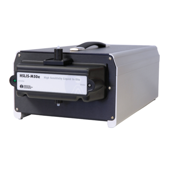
Chapter 1 Introduction The HSLIS e-Series particle counter models include: • HSLIS M50e • HSLIS M65e • HSLIS M100e HSLIS-M50e particle counter Figure 1-1 These High Sensitivity Liquid In Situ Monitors (HSLIS) sample DI water or process chemicals to measure the presence of particles. These instruments use laser illumination with a high resolution optical system, collecting particle-scattered light over the range of angles ±... -
Page 15: Chapter 1: Introduction
Chapter 1 : Introduction A current-monitoring circuit is incorporated in the laser diode assembly to determine if the laser diode is functioning properly. 4-20 mA ETHERNET RS-232 POWER/FUSE Figure 1-2 HSLIS e-Series Particle Counter – Front and Rear Views HSLIS e-Series Operations Manual... -
Page 16: Specifications
Chapter 1 : Introduction Specifications Specifications M50e M65e M100e Size range 0.05 – 0.2 mm 0.065 – 0.2 mm 0.1 – 1.0 mm Channels Channel sizes 0.05, 0.1, 0.15, 0.2 mm 0.065, 0.1, 0.15, 0.2 mm 0.1, 0.2, 0.5, 1.0 mm Optimum flow rate 100 ±... - Page 17 Chapter 1 : Introduction Specifications This page is intentionally left blank. HSLIS e-Series Operations Manual...
-
Page 18: Chapter 2: Unpacking & Installation
Chapter 2 Unpacking & Installation Unpacking Unpack the HSLIS e-Series particle counter and ensure that all components have been received. Standard shipping list: • Power cable • RS-232 configuration cable with RJ-11 male connectors on each end • DB-9 to RJ-11 adapter •... -
Page 19: Recycling
Chapter 2 : Unpacking & Installation Recycling Recycling As a global leader in contamination monitoring, Particle Measuring Systems (PMS) has also been actively monitoring and reducing our environmental contamination over the last few years. With your shipment, you receive packaging materials that can be 100% recycled. For up to date, detailed information about recycling the specific materials in your this link. -
Page 20: Installation
Chapter 2 : Unpacking & Installation Installation Installation Installation consists of the following activities: • Moving the instrument to the area where it will be used. See Moving the Instrument to the Work Area on page 2-3. • Installing the instrument’s plumbing connections. See Installing the Plumbing Connections on page 2-3. -
Page 21: Connecting The Cables
Chapter 2 : Unpacking & Installation Status LED NOTE: The flow rate should be set with an external flow controller. Whatever flow controller is used, ensure that it can be set to a flow rate of 100 mL/minute for the M50e and M65e models of the HSLIS particle counters and to a flow rate of 300 mL/minute for the M100e model of the HSLIS particle counter. -
Page 22: Chapter 3: Set Up For Ethernet Communications
Chapter 3 Set Up for Ethernet Communications When using Facility Net as your HSLIS e-Series particle counter interface, you must communicate over an Ethernet network. Before you can communicate over an Ethernet network you must set the correct IP addresses in the particle counter instrument. -
Page 23: Connecting A Computer To The Particle Counter
Chapter 3 : Set Up for Ethernet Communications Connecting a Computer to the Particle Counter Connecting a Computer to the Particle Counter >> To connect a computer to the particle counter: Assemble the HSLIS e-Series particle counter, computer, and RS-232 cable in a suitable work location. -
Page 24: Figure 3-1 Hyperterminal Window
Chapter 3 : Set Up for Ethernet Communications Setting Up a Terminal Emulation Session >> To set up a terminal emulation session: Open your HyperTerminal program. The HyperTerminal window appears (see Figure 3-1). Figure 3-1 HyperTerminal window NOTE: Your HyperTerminal window may have a different display of icons. Double-click the HyperTerminal icon. -
Page 25: Figure 3-3 Connect To Window
Chapter 3 : Set Up for Ethernet Communications Setting Up a Terminal Emulation Session Figure 3-3 Connect To window Complete the following fields in the Connect To window: • Country code • Area code • Phone number Select Com 1 or Direct to Com 1 in the Connect using field. Click OK in the Connect To window. -
Page 26: Running A Status Check
Chapter 3 : Set Up for Ethernet Communications Running a Status Check Complete the following fields in the Com1 Properties window: • Bits per second – Enter 9600. • Flow control – Enter None. 10. Click OK in the Com1 Properties window. HyperTerminal tests COM1 to verify that the link is running. -
Page 27: Setting Ip Addresses
Chapter 3 : Set Up for Ethernet Communications Setting IP Addresses Figure 3-6 COM HyperTerminal window with Status Check Setting IP Addresses You may be using a multicast and/or gateway address as well. Commands to set these addresses are given below. >>... -
Page 28: Figure 3-7 Com Hyperterminal Window
Chapter 3 : Set Up for Ethernet Communications Setting IP Addresses Figure 3-7 COM HyperTerminal window Use the following commands, as needed, at the HyperTerminal prompt. Press Enter after each command line. Displays a command summary. Displays the current firmware version number, MAC address, IP address, Multicast address, net mask address, gateway address, connection status, and 4-20 mA parameters. -
Page 29: Connecting The Ethernet Cable
Chapter 3 : Set Up for Ethernet Communications Connecting the Ethernet Cable set gateway aaa.bbb.ccc.ddd Sets the gateway address in a decimal notation form of Each 3- aaa.bbb.ccc.ddd. digit series represents a value from 0 – 255, separated by a period (.). This address is unique to the hardware it serves. -
Page 30: Straight Through Ethernet Cable Pinouts
Chapter 3 : Set Up for Ethernet Communications Connecting the Ethernet Cable • If you are connecting the monitor into a hub of other monitors, use an Ethernet straight-through cable between monitor and hub as well as from the hub to the computer. -
Page 31: Crossover Ethernet Cable Pinouts
Chapter 3 : Set Up for Ethernet Communications Connecting the Ethernet Cable Crossover Ethernet Cable Pinouts Table 3-3 Ethernet crossover cable pinouts CROSSOVER CABLE PINOUTS Function Compute Particle Function Counter Pin 1 Pin 3 Pin 2 Pin 6 Pin 3 Pin 1 Pin 4 Pin 4... -
Page 32: Chapter 4: Operations
Chapter 4 Operations This chapter discusses the following topics: • Setting sample parameters (see below) • Calculating sample parameters (see Calculating the Sample Interval on page 4-2) • Using HyperTerminal as the user interface to HSLIS e-Series particle counter (see Starting the HyperTerminal Program on page 4-3) •... -
Page 33: Calculating The Sample Interval
Chapter 4 : Operations Calculating the Sample Interval Calculating the Sample Interval HSLIS M65 particle counter sample parameters are Sample Interval. This section discusses how the sample interval is calculated. You will use this calculation to set the sample interval when using either HyperTerminal or Facility Net. See Setting the Sample Interval on page 4-2 The sample interval setting is determined based on the following: •... -
Page 34: Starting The Hyperterminal Program
Chapter 4 : Operations Setting the Sample Interval Starting the HyperTerminal Program NOTE: The following steps and images are specific to a particular version of HyperTerminal. Your version may be different and, therefore, require some variation in the steps. The overall process is the same. >>... -
Page 35: Using Facility Net With The Hslis E-Series Particle Counter
Chapter 4 : Operations Using Facility Net with the HSLIS e-Series Particle Counter Figure 4-2 HyperTerminal session window At the prompt, type the following sample interval command with the two sample interval variables, x and y, in seconds: set sample x y This function sets the sample interval to x seconds. - Page 36 Chapter 4 : Operations Using Facility Net with the HSLIS e-Series Particle Counter If you are using a computer with the Facility Net software, you must complete the following steps. >> To connect the particle counter to Facility Net: Connect the Ethernet cable between the particle counter and computer. Set addresses for the HSLIS e-Series particle counter.
- Page 37 Chapter 4 : Operations Using Facility Net with the HSLIS e-Series Particle Counter This page is intentionally left blank. HSLIS e-Series Operations Manual...
-
Page 38: Chapter 5: Operating With The 4-20 Ma Outputs
Chapter 5 Operating with the 4-20 mA Outputs The HSLIS e-Series particle counter sends 4-20 mA signals that can be integrated into a SCADA, PLC (Programmable Logic Controller) or other device that can interpret 4-20 mA signals. The following data signals are output: •... -
Page 39: Connecting A Computer To The Particle Counter
Chapter 5 : Operating with the 4-20 mA Outputs Connecting a Computer to the Particle Counter Connecting a Computer to the Particle Counter >> To connect a computer to the particle counter: Assemble the HSLIS e-Series particle counter, computer, and RS-232 cable in a suitable work location. -
Page 40: Setting 4-20 Ma Parameters
Chapter 5 : Operating with the 4-20 mA Outputs Setting 4-20 mA Parameters Figure 5-1 HyperTerminal window NOTE: Your HyperTerminal window may display a different set of icons. Double-click the HyperTerminal icon. The new HyperTerminal session appears in the HyperTerminal window. Figure 5-2 HyperTerminal window Setting 4-20 mA Parameters The following commands are used to set 4-20 mA parameters. - Page 41 Chapter 5 : Operating with the 4-20 mA Outputs Setting 4-20 mA Parameters Enter any of the following commands at the HyperTerminal prompt, and press the Enter key. set cumul n This function selects between cumulative and differential data for the 4-20 mA channels.
-
Page 42: Connecting Hslis E-Series Particle Counter To Scada Or Plc
Chapter 5 : Operating with the 4-20 mA Outputs Connecting HSLIS e-Series Particle Counter to SCADA or PLC Connecting HSLIS e-Series Particle Counter to SCADA or PLC Connection to the 4-20 mA output option is made using a standard DE-25 D-type connector. - Page 43 Chapter 5 : Operating with the 4-20 mA Outputs Factory Preset Status Levels This page is intentionally left blank. HSLIS e-Series Operations Manual...
-
Page 44: Chapter 6: Maintenance
Chapter 6 Maintenance Cleaning Optics The sample cell window and optics may become dirty. Optics should only be cleaned by a technician certified by Particle Measuring Systems. Calibration Calibration should be checked at least once each year by a technician certified by Particle Measuring Systems. -
Page 45: Dc Light
Chapter 6 : Maintenance DC Light Replace the fuses and then replace the fuse drawer. Plug the unit into its power source. Start the HSLIS e-Series Particle Counter with the power switch. DC Light DC light is continuously monitored by the firmware. The values that vary between 0.00 (good) and 1.00 (high DC light) represent the percentage of time during the sample interval that the DC light was high. -
Page 46: Appendix A: International Precautions
Appendix A International Precautions WARNING This instrument is designated as a Class 1 laser product and complies with US 21 CFR 1040.10 and EN 60825-1. Use of controls, or adjustment, or performance of procedures other than those specified in this manual may result in hazardous radiation exposure. AVERTISSEMENT Cet appareil est classé... -
Page 47: Hazard Symbols
Appendix A : International Precautions Hazard Symbols Hazard Symbols The meaning of hazard symbols appearing on the equipment is as follows: Symbol Nature of Hazard Attention, consult accompanying documents. Dangerous High Voltage Warning – Laser radiation! Avoid exposure to beam. Symboles de risque Des symboles représentant les risques sont placés sur l'appareil. -
Page 48: Simboli Di Pericolo
Appendix A : International Precautions Simboli di pericolo Warnung – Laserstrahlung! Nicht in den Strahl blicken. Simboli di pericolo Il significato dei simboli di pericolo che appaiono sugli strumenti il seguente: Simbolo Natura del pericolo Attenzione. Consultare i documenti allegati Tensione Pericolosa Avvertenza –... - Page 49 Appendix A : International Precautions Simbolos de peligro This page is intentionally left blank. HSLIS e-Series Operations Manual...
-
Page 50: Appendix Bled Indications
Appendix B LED Indications This appendix decodes the HSLIS e-Series particle counter status and activity LED indicators. The material is organized by the type of communications, Ethernet (see below) or RS-485 (see page B-2). Ethernet Communications 4-20 mA output and Ethernet communications are automatically and continuously available when the HSLIS e-Series particle counter is on. -
Page 51: 4-20 Ma Output Without Host (Facility Net) Control
Appendix B : LED Indications 4-20 mA Output without Host (Facility Net) Control Status LED Activity LED Steady amber Warning Steady red Alarm Use Facility Net’s Event Log to identify the event that changed the LED status. >> To see the event log: Click Configure >... -
Page 52: Appendix C: 有毒或有害的物质和元素
Appendix C 有毒或有害的物质和元素 有毒或有害的物质和元素 Part Name 铅 汞 镉 六价铬 多溴联苯 多溴联苯醚 部件名称 (Pb) (Hg) (Cd) (Cr(VI)) (PBB) (PBDE) 电源供应 印刷电路装配 光学元件 激光 机械部件 电缆 机电 O: 表示用于部件的所有同族物质中所含的有毒或有害物质低于SJ/T11363-2006规定的限 度要求。 X: 表示用于部件的至少一种同族物质中所含的有毒或有害物质高于SJ/T11363-2006规定 的限度要求。 HSLIS e-Series Operations Manual... -
Page 53: Appendix C: 有毒或有害的物质和元素
Appendix C : 有毒或有害的物质和元素 This page is intentionally left blank. HSLIS e-Series Operations Manual... -
Page 54: Appendix D Modbus
Appendix D Modbus Communications with the HSLIS e-Series e-Series are available via Modbus TCP. The instrument presents a single TCP/IP Ethernet connection at port 502 using the standard Modbus protocol. Two specification documents were used in the development of the Modbus interface: •... -
Page 55: Appendix D: Modbus
Appendix D : Modbus Modbus Overview The map delineates three types of register assemblies: Unary: an individual register Dual: a register pair used for a 32 bit representation String: a group of registers containing ASCII bytes There is a setting available that toggles the interpretation of selected dual-register values. -
Page 56: Input Registers
Appendix D : Modbus Input Registers Input Registers The input registers are in two sections: Configuration and Data. The Configuration section description begins on this page. The Data section description begins on page D-5. Configuration Section The input registers are in two sections: Configuration and Data. The Configuration section contains: •... -
Page 57: Table D-1 Input Register - Configuration
Appendix D : Modbus Input Registers 30012: The power of 10 multiplied to the volume and then entered into Volume Scale Factor registers 30224/30225. Used when the floating-point representation is disabled. The scale factor depends on the sample flow rate. If the sample flow rate is less than 1.0 ml/min the factor is 5. -
Page 58: Data Section
Appendix D : Modbus Input Registers Table D-1 Input Register – Configuration (Continued) Input Registers Description Comment Notes (Configuration) 30016 unary Number of Analog Channels Fixed number of analogs 1 fixed 30017 dual Channel 1 Size (high) nanometers 30018 dual Channel 1 Size (low) nanometers Type... - Page 59 Appendix D : Modbus Input Registers 30214: Least Significant byte (LSB) is State. Most Significant Byte (MSB) is sub-state. Values are defined in Table D-5 on page -13. Device State 30215: A value of zero is identical to no data available (coil 00/02 read as Number of Data Samples zero).
-
Page 60: Table D-2 Input Register - Data Packet
Appendix D : Modbus Input Registers 30237 - 30238: Dual-register representation of the data packet analog value. Can be integer or float depending on the mode selected. The integer value Analog Data represents the scaled DC Light input multiplied by 10000. Integer representation limited to a value between -214748.3648 to 214748.3647. - Page 61 Appendix D : Modbus Input Registers Table D-2 Input Register – Data Packet (Continued) Input Registers Description (Data Packet) Comment Notes 30228 unary Number Analog Channels Variable across types 1 fixed 30229 dual Particle Channel 1 (high) Cumulative Raw Ch1 30230 dual Particle Channel 1 (low)
-
Page 62: Holding Registers
Appendix D : Modbus Holding Registers Holding Registers Like the coils, spares are in place between the "standard" registers and those that are designated as specific/optional. There are no specific/optional coils defined for the HSLIS e-Series. If sample setting holding registers are sent while the unit is sampling, it will transition to a state of Idle. -
Page 63: Coils
Appendix D : Modbus Coils Coils Like the holding registers, spares are in place between the "standard" coils and those that are specific/optional. There are no specific/optional coils defined for the HSLIS e-Series. 00/01: The data collection coil will enable/disable sampling. Read: 1=Sampling Enabled, 0=Sampling Disabled. -
Page 64: Table D-4 Coils
Appendix D : Modbus Coils 00/10 - Spare. 00/32: Read: Always 0 Write: No effect Table D-4 Coils Coils Description (Coils) Comment 00/01 Data Collection On/Off Sampling Control 00/02 Data Available Yes/No Data Available/Queue Control 00/03 Data Clear Toggle Data Queue Delete 00/04 Reset Sensor Toggle... -
Page 65: Data Packet Processing
Appendix D : Modbus Data Packet Processing Data Packet Processing The unit can provide real-time data or queued data or both. There is only one section of input registers assigned for data to handle this information. If the unit is setup to queue data then the data shown is the oldest data in the queue. The data available coil (00/02) will be set on a read if there is data in the queue. -
Page 66: Associated Values For Specific Registry Entries
Appendix D : Modbus Associated Values for Specific Registry Entries Associated Values for Specific Registry Entries Table D-5 Associated values for specific registry entries Device Status 0x0001 Data Collection Matches the common coil settings Entries 0x0002 Data Available 0x0004 Data Clear 0x0008 Reset 0x0010... -
Page 67: Modbus Processing Example
Appendix D : Modbus Modbus Processing Example Modbus Processing Example The following flowchart provides a basic example of controlling the HSLIS e-Series using Modbus protocol. The flowchart is meant to be a starting point. It does not detail error handling and does not provide other functionalities which may be desired. Figure D-1 Modbus flowchart D-14 HSLIS e-Series Operations Manual... - Page 68 Index counting efficiency 1-3 Symbols crossover cable, Ethernet 3-8 pinouts 3-10 ? HyperTerminal command 3-7 cumulative data 5-4 Customer Response Center 2-1 Activity LED 2-4 addresses, setting IP 3-6 DC light values 6-2 DE-25 D-type connector 5-5 pinouts 5-5 differential data 5-4 dimensions 1-3 bubble formation 2-3 bubbles 2-4...
- Page 69 Index message "Unable to open COM1" set led n 5-4 set raw n 5-4 HyperTerminal 3-5 set scale n 5-4 session 3-2 status 5-4 starting 3-2 write 5-4 operations 5-1 setting parameters 5-3 without host (Facility Net) control B-2 installation 2-3 fuses 1-3 connecting a PC to the particle counter 3-2 replacing 6-1...
- Page 70 Index sample parameters 4-1 setting up Ethernet communications 3-1 PC, connecting to the HSLIS particle counter 3-2 terminal emulation session with pinouts HyperTerminal 3-2 crossover Ethernet cable 3-10 shipping container, storing 2-1 DE-25 connector 5-5 shipping list 2-1 straight-through Ethernet cable 3-9 software for use with HSLIS particle counter 4-4 PLC 5-1 software, Facility Net 3-1...
- Page 71 Index Index-4 HSLIS e-Series Operations Manual...
Need help?
Do you have a question about the PARTICLE MEASURING SYSTEM HSLIS e-Series and is the answer not in the manual?
Questions and answers