Mindray MX7 Quick Start Manual
Diagnostic ultrasound device
Hide thumbs
Also See for MX7:
- Operator's manual (312 pages) ,
- Service manual (292 pages) ,
- Operator's manual (338 pages)
Table of Contents
Advertisement
Quick Links
Advertisement
Table of Contents

Related Manuals for Mindray MX7


Summary of Contents for Mindray MX7
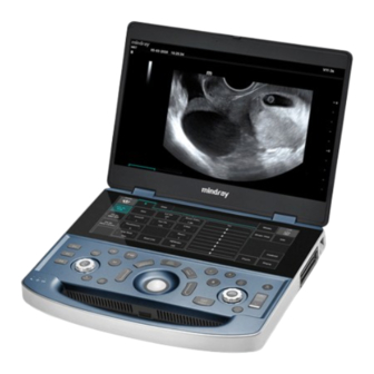
- Page 1 Mindray MX7 Diagnostic ultrasound device Quick Start Guide...
-
Page 2: Table Of Contents
Table of contents 1.Safety requirements……………………………………………..3 2. System overview ……………………………………………..10 3. Preparation of the study ……………………………………..15 4. Optimizing the Image ………………………………………..19 5. Measurements ………………………………………………..34 6. Comments and bodymarks ………………………………..36... -
Page 3: Safety Requirements
1. Safety requirements Warning words, explanations In this manual, the signal words DANGER, WARNING, CAUTION, NOTICE, and description are used for safety and other important instructions. Signal words and their meanings are defined as follows. Before reading this manual, clearly understand its meaning. Warning meaning Indicates a hazardous situation which, if not avoided, could result in death... -
Page 4: Safety Measures
If water is accidentally sprayed into the system or entered immediately, turn off the system and contact Mindray customer service or a sales representative. - Page 5 The connected analog and digital interfaces of the accessories must comply with the relevant IEC standards (eg IEC 60950 IT technical safety level and IEC 60601-1 medical technology standard). Moreover, all configurations comply with the IEC 60601-1 Section 16 ME system. The person who connects the accessory signal input or output ports and configures the medical system is responsible for ensuring that the system meets the requirements of IEC 60601-1 clause 16 ME system.
- Page 6 Use components that comply with applicable local regulations. Use the disinfectant solutions recommended in this manual; otherwise Mindray will not be liable for damages due to the use of other solutions. If you have any questions, contact Mindray Customer Service or a sales representative.
-
Page 7: Intellectual Property Statement
Mindray is strictly forbidden. , BeneView, WATO, BeneHeart, are the trademarks, registered or otherwise, of Mindray in China and other countries. All other trademarks that appear in this manual are used only for informational or editorial purposes. They are the property of their respective owners. -
Page 8: Responsibility On The Manufacturer Party
Contents of this manual are subject to change without prior notice. All information contained in this manual is believed to be correct. Mindray shall not be liable for errors contained herein or for incidental or consequential damages in connection with the furnishing, performance, or use of this manual. -
Page 9: Warning Stickers
Warning stickers Warning labels are included in the system to draw attention to potential hazards. The symbol on the warning labels indicates safety requirements. The safety label using the same signal words is used in the instruction manual. Before you start working on the system, carefully read the instruction manual. -
Page 10: System Overview
2. System overview Intended use This ultrasound system is intended for use in obstetrics, gynecology, abdominal, pediatric, small parts, musculoskeletal, cardiovascular, urological, nerve examinations. Contraindications The diagnostic ultrasound system is not intended for use in ophthalmology. Study modes B mode B M mode M Free Xros M Free Xros CM... - Page 11 System overview...
- Page 12 Name Function <1> Monitor Displays images and parameters during scanning. <2> Touchscreen Operator-system interface or control device that touches the display. <3> Power button Used to turn the power supply on / off. <4> S-Video S-Video signal expression. <5> Network port Network connection.
- Page 13 Control panel Name Description <1> Entering TDI mode. <2> Entering CW mode. <3> Entering M mode. <4> Entering PW mode. Enter / exit application measurement mode. <5> Measure <6> Update Toggle key: Press to change the active window. Start / stop capturing an image in iScape or 3D / 4D mode. <7>...
- Page 14 <14> Depth Adjust the depth in real time. <15> Save Recording recording. <16> Freeze Still image. Confirm the operation. The function is the same as with a left mouse <17> button on a computer. <18> Trackball Move the trackball to reposition the cursor. <19>...
-
Page 15: Preparation Of The Study
3.Preparation of the study The patient's study can be started in the following situations: • New patient information: To start a new patient study, you must first enter patient information. • New Study: For an already registered patient to start a new study, the saved information can be obtained via iStation or Worklist. - Page 16 Move the cursor over the desired box. The box is highlighted and a flashing cursor appears. You can enter information or select from options. You can also change the cursor position using the <Tab>, <Enter> or up / down buttons: 1.
- Page 17 Receiving Patient Information iStation Patient data is stored on the iStation's system hardware or USB storage device. You can enter patient search criteria. 1. To enter the IStation screen (screen shown below): Press <iStation> or on the keyboard Select [iStation], or on the patient information screen ...
-
Page 18: Ending A Study
Select to open the diagnostic report Review Report Delete Exam Select to delete the selected study Backup Exam Select to save the selected patient study to supported media Select to import patient data from external media Restore Exam Select a DICOM storage server, memory stick, or printer to send the Send Exams selected patient data to an external device Activate Exams... -
Page 19: Image Optimization
4. Image optimization Mode B image optimization B-mode is the basic imaging mode that displays real-time images of anatomical tissues and organs. Enter patient information. Select the appropriate probe and test mode. Press the <B> button on the control panel to enter B mode. Adjust the parameters to optimize the image. - Page 20 Depth This function is used to adjust the depth of the image, the value of which is Description displayed in real time in the image parameter area at the top right of the scree Description To optimize the image, the system compensates for signals from deeper tissue by segments.
- Page 21 Dynamic Range Description This function is used to adjust the B-image resolution to compress or expand the gray screen. The real-time value is displayed in the upper right corner of the screen in the image parameter area. Adjust the dynamic range on the touch screen.
- Page 22 TSI (Tissue Specific Imaging) Description The TSI function is used to optimize the image by selecting the acoustic speed according to the tissue properties. iTouch (Auto Image Optimization) Description To optimize image parameters according to tissue properties. H Scale Description Show or hide the width scale (horizontal scale).
- Page 23 M mode image optimization Select a high-quality image while scanning a B-mode and align the area of interest with the center of the B-mode image. Press the <M> button on the control panel and turn the trackball to adjust the sampling line. Press the <M>...
- Page 24 Gray Map Description This function applies gray scale correction for optimal image. Edge Enchance Description This function is used to enchance the image profile to differentiate the border of image. Dynamic Range This function is used to adjust the M-image resolution to compress or Description expand the gray screen.
- Page 25 Color mode image optimization Color Doppler mode is used to detect color flow information and to estimate the direction and speed of blood flow. Select a high-quality image while scanning a B-mode and align the area of interest with the center of the B-mode image.
- Page 26 ROI Adjustment Description This feature adjusts the width and position of the ROI in color mode. Image Quality Description Responsible for the probe operating frequency in color mode, the real-time displayed value is displayed in the image parameter area in the upper right corner of the screen.
- Page 27 Baseline Description Refers to an area where the speed on the scale is zero. Adjust according to the actual situation to obtain the optimal current display. Invert Description Set the color flow display mode. When the function is switched on, the color scale is rotated.
- Page 28 Power mode image optimization Power mode (amplitude doppler) provides non-directional display of blood flow in terms of intensity and flow rate. DirPower (directional power mode) provides additional information about the direction of current toward or away from the probe. 1. Select a high-quality image while scanning a B-mode and align the area of interest with the center of the B-mode image.
- Page 29 PW / CW Doppler mode PW (Pulsed Wave Doppler) mode or CW (Continuous Wave Doppler) modes are used to obtain the speed and direction of blood flow using a real-time spectral display. Control units such as SV, Steer, Duplex, Triplex, iTouch and HPRF are not available in CW mode.
- Page 30 PW / CW mode image optimization Gain Description The purpose of this function is to adjust the gain of the spectrum card. The real-time gain value is displayed in the image parameter area at the top right of the screen. Description To adjust the SV position and output size in PW mode, is displayed SV and SVD in the real-time image parameter area, in the upper right...
- Page 31 Auto-Calculation Description This function is used to calculate PW / CW mode image parameters. The results are displayed in the results window. 1.Touch [Auto Calc] on the touch screen to turn the automatic calculation function on or off. 2. After the automatic calculation function is turned on, touch the "Auto Calculation" tab.
- Page 32 T/F Res. Description This function is used to strike a balance between time resolution and spatial resolution. Wall Filter Description This function is used to strike a balance between time resolution and spatial resolution. Tint Map This feature provides an image display process based on color difference Description rather than gray color separation.
- Page 33 Dynamic Range Description The dynamic range transmits information that changes from echo intensity to grayscale. Audio Description This function is used to adjust the output sound. Turn the <Volume> knob on the left side of the touch panel to adjust the volume. PW Steer This function is used to adjust the angle oft he sampling gates.
-
Page 34: Measurements
Measurements 2D Basic measurements The following measurements can be made: Measurement Function Distance Measures the distance between two points of interest. Measures the distance between the surface of the probe and the point to be Depth probed, along the ultrasonic wave. Angle Measures the angle between two intersecting planes. - Page 35 Basic Doppler measurements The following measurements can be made: The measurements listed below can be made: Measurement Function means Time Measures the time interval between any two points. The N-intervals (n≤8) are measured to calculate the HR value derived from the PW mode, beats per minute (BPM).
-
Page 36: Comments And Bodymarks
Comments and body notes 6.1 Comments It is possible to comment on the ultrasound image in order to draw attention, mark or transmit the information observed during the examination. Comments can be added to enlarged images, review images, live images, frozen images. Comments can be entered in characters, predefined comments can be entered through the comment library, and arrows can also be entered. -
Page 37: Deleting Comments
Deleting comments Delete commented characters, text, or arrows Move the cursor over the comment you want to delete. Press <Set> to select a comment. Press <Backspace>, <Del>> or <Clear> to delete the comment. Delete a recently added character, text, or arrow After adding multiple comments, when the cursor displays the status "|"... - Page 38 Select the desired body mark directly on the touch screen. To adjust the position and direction of the probe: Move the trackball to the appropriate position to determine the position. • Turn the <Steer> knob to adjust the direction. •...
Need help?
Do you have a question about the MX7 and is the answer not in the manual?
Questions and answers
какая емкость стандартного аккумулятора ? Напряжение?
The standard battery for the Mindray MX7 is a Lithium-Ion Battery Pack with a capacity of 6600mAh and a voltage of 14.4V.
This answer is automatically generated