
Related Manuals for Mindray DP-8800Plus


Summary of Contents for Mindray DP-8800Plus
- Page 1 DP-8800Plus/DP-9900Plus/DP-9900 Digital Ultrasonic Diagnostic Imaging System Service Manual...
- Page 2 Mindray, nor the rights of others. Mindray does not assume any liability arising out of any infringements of patents or other rights of third parties.
- Page 3 FITNESS FOR ANY PARTICULAR PURPOSE. Exemptions Mindray's obligation or liability under this warranty does not include any transportation or other charges or liability for direct, indirect or consequential damages or delay resulting from the improper use or application of the product or the use of parts or accessories not approved by Mindray or repairs by people other than Mindray authorized personnel.
- Page 4 Returned shipments will not be accepted if the Mindray number is not clearly visible. Please provide the model number, serial number, and a brief description of the reason for return. Freight policy: The customer is responsible for freight charges when this product is shipped to Mindray for service (this includes customs charges).
- Page 5 Safety Precautions Meaning of Signal Words DANGER, WARNING In this operation manual, the signal words and NOTE are used regarding safety and other important instructions. The CAUTION signal words and their meanings are defined as follows. Please understand their meanings clearly before reading this manual.
- Page 6 Safety Precautions Please observe the following precautions to ensure patient and operator safety when using this system. DANGER: Do not use flammable gasses such as anesthetic gas, oxygen or hydrogen, or flammable liquids such as ethanol, near the system, because there is danger of explosion. WARNING: 1....
- Page 7 9. Do not use the transducers other than those provided by Mindray. If a transducer other than those provided by Mindray is connected, the equipment and the transducer may be damaged, causing an accident such as a fire in the worst case.
- Page 8 15. Prolonged and repeated use of keyboards can result in hand or arm nerve disorders in some individuals. Observe the local institution work safety/health regulations on keyboard use. CAUTION: 1.Precautions concerning clinical examination techniques (1) This system can only be used by medical personnel fully trained in clinical examination techniques.
- Page 9 7. If the circuit breaker is tripped or the fuse is blown, it indicates that the machine or the peripheral devices have problems. In these cases, the user cannot repair by him but contact the Mindray sales office, customer service department or representative.
- Page 10 10.Before examining a new patient, press 『Patient』 to delete the patient information and data recorded in the memory for the previous patient. Otherwise, the new data may be confused with the data of the previous patient. 11. Do not pull out plugs of the system and its accessories without turning OFF the power.
- Page 11 9. If the system is used in a small room, the room temperature may rise. Therefore, proper ventilation shall be provided. 10. The fuse, which is inside the machine, can be replaced only by the Mindray service engineer or the technician specified by Mindray.
-
Page 12: Table Of Contents
Contents Chapter 1 System Introduction .............. 1-1 1.1. Introduction of DP-8800Plus ................1-1 1.1.1. Appearance .................... 1-1 1.1.2. Rear Panel ..................... 1-3 1.1.3. Control Panel ..................1-4 1.2. Introduction of DP-9900Plus/DP-9900 ............1-6 1.2.1. Appearance .................... 1-6 1.2.2. Rear Panel ..................... 1-8 ... - Page 13 3.17. Replacing the inverter board and control board of the LCD ......3-20 3.18. Replacing the LCD screen of the LCD Monitor ..........3-21 3.19. Disassembly of the LCD support arm assembly ........... 3-23 Chapter 4 Disassembly of DP-8800Plus ..........4-1 4.1. System Structure .................... 4-1 ...
- Page 14 Contents 4.8. Disassembly of Transducer Cable Hanger ............4-6 4.9. Disassembly of Handle ................... 4-7 Chapter 5 Maintenance Requirements ..........5-1 5.1. Tools and Consumables .................. 5-1 5.2. Maintenance Personnel .................. 5-2 Chapter 6 System Maintenance ............. 6-1 ...
-
Page 15: Chapter 1 System Introduction
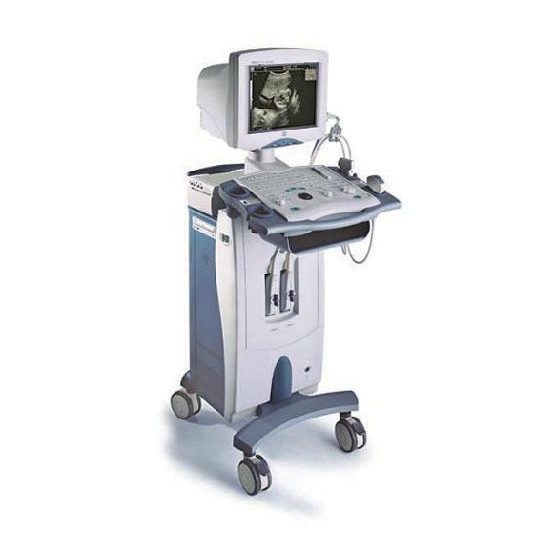
Chapter 1 System Introduction 1.1. Introduction of DP-8800Plus 1.1.1. Appearance <1> <2> <3> <5> <4> <6> <7> <8> <5> <9> <6> <7> <10> Front View... - Page 16 System Introduction <11> <12> <13> <14> Left View Part Introduction <1> Monitor Display images and parameters, etc. <2> Transducer cable Hook for the transducer cable hanger <3> Transducer holder Place the transducer provisionally <4> Printer area Place the video printer <5>...
-
Page 17: Rear Panel
System Introduction 1.1.2. Rear Panel Rear View < > < > < > <20> <21> < > < > <20> I/O Panel Name Introduction Connect the video printer or other video device <15> Video out... -
Page 18: Control Panel
System Introduction Name Introduction <16> Graph/text printer Connects the graph/text printer port Video output <17> S-Video port Rreserved <18> RS-232 <19> VGA port VGA output <20> USB port Connects the USB storage device or graph/text printer, etc. <21> Ethernet port Connects network <22>... - Page 19 System Introduction Function <1> Patient Delete the data for the previous patient, including the ID and measured values, and begin with a new patient. <2> Info The patient information screen appears. <3> Preset Invoke the registered initial settings (presets). <4> File Activate storage or load files system <5>...
-
Page 20: Introduction Of Dp-9900Plus/Dp-9900
System Introduction Function <27> Depth/Zoom/ Adjust the viewing depth for display, the zoom mode, and the Rotation arrow rotation of the ultrasound images. <28> Cine Switch Manual/Auto CINE review. When the 『Cine』 lamp lights on, the system enter Manual Review mode; when the 『Cine』... - Page 21 System Introduction <6> <7> <8> <9> Left View Part Introduction <1> Monitor Display images and parameters, etc. 14″ monitor <2> Transducer cable Hook for the transducer cable hanger <3> Transducer holder Place the transducer provisionally <4> Transducer socket Connect or disconnect the transducer with the main unit <5>...
-
Page 22: Rear Panel
System Introduction 1.2.2. Rear Panel Rear View I/O Panel... - Page 23 System Introduction Power Panel Name Introduction <10> VGA port VGA output <11> S-Video port Video output <12> Video output Connects a video printer <13> Video output Connects a video printer <14> Remote Connects the remote cable for the video printer <15>...
-
Page 24: Control Panel
System Introduction 1.2.3. Control Panel < > <1> <2> <3> <4> < > < > < > < > <8> < > < > <30> < > < > < > A B C < > < > < > <... - Page 25 System Introduction Function <12> Select the combination of image processing parameters, to adjust the image display effect. <13> Parameter adjust knob Adjust some value of Puncture, F.Posi, F.Num, A.Power and IP with combination of corresponding key. <14> Clear Clear all comments, bodymarks, measurement scales and general measurement results on the screen <15>...
-
Page 26: Chapter 2 Hardware Introduction
Chapter 2 Hardware Introduction 2.1. Hardware System The hardware system consists of the transducer unit, tranmission unit, amplification unit, beam forming unit, B/M signal processing unit, DSC unit, CPU system, I/O unit and power supply unit. The hardware system is shown as the figure below. 2.2. -
Page 27: Transducer Board
Hardware Introduction The front-end transmission circuit consists of MD1210 and TC2320. The reception circuit includes ADG714, VCA8617 and ADS5277. The transmission sequence control and reception channel selection are completed by FPGA. The digital circuit consists of the CPU system and the FPGA system. The CPU system includes CPU and the peripheral and interface circuit: FLASH, SDRAM, CPLD, power monitor (ADT7462), reset circuit, clock circuit, real-time clock circuit (MAX6900), IDE interface, USB interface, and Ethernet interface;... -
Page 28: Connection Board
The board, which is grounded well and conforms to the requirements of EMC, can filter differential mode and common mode noise. DP-9900, DP-9900Plus and DP-8800Plus all use the board. The diagram of the connection board is shown as follows. - Page 29 Hardware Introduction Keyboard CD-ROM Display Upper Fan Diskette Drive Hard Disk 5v,12v 5v,12v 5v,12v 5v,12v 13.5v 4pin*3 6pin 4pin Transducer Board Main Board POUT[128:81] 5V,12V 13.5V 5V,12V,13.5V POUT[80:1] FID[8:1] Transducer High-frequency Filter Main Board NAIDRD Board NBIDRD EX_EN Power Supply D+5,D12V,A13V5 Board D12V...
- Page 30 Hardware Introduction 13V5 13V5 13V5 2.2.3.2. Interfaces to Main Board The interfaces between the connection board and the main board are defined in the table below. FA-5 FA-5 FA-5 FA-5 FA-5 FA+5 FA+5 FA+5 FA+5 FA+5...
- Page 31 Hardware Introduction FA+5 FA+5 FA+5 FA+5 FA+5 FA3V FA3V FA3V FA3V FA3V F1V2 F1V2 F1V2 F1V2 F1V2 F1V2 F1V2 F1V2 F1V2 F1V2 FD3V3 FD3V3 FD3V3 FD3V3 FD3V3 FD3V3 FD3V3 FD3V3 FD3V3 FD3V3 13V5 FD+5 FD+5 FD+5 FD+5 FD+5 FD+5 FD+5 FD+5 FD+5 FD+5...
- Page 32 Hardware Introduction POUT2 POUT15 POUT14 POUT16 POUT4 POUT13 POUT11 POUT12 POUT1 POUT10 POUT6 POUT9 POUT3 POUT7 POUT8 POUT5 POUT22 POUT25 POUT28 POUT26 POUT19 POUT20 POUT24 POUT27 POUT31 POUT21 POUT32 POUT30 POUT29 POUT18 POUT23 POUT48 POUT34 POUT45 POUT17 POUT46 POUT36 POUT42 POUT47 POUT41 POUT33...
- Page 33 Hardware Introduction POUT99 POUT102 POUT107 POUT105 POUT97 POUT104 POUT101 POUT126 POUT121 POUT103 POUT122 POUT128 POUT125 POUT127 POUT123 POUT124 POUT119 POUT120 POUT117 POUT118 POUT114 POUT113 POUT116 POUT115 FID1 FID2 FID3 FID4 FID5 FID6 FID7 FID8 /AIDRD /BIDRD POUT2 POUT15 POUT14 POUT16 POUT4 POUT13 POUT11...
-
Page 34: Output Board
Hardware Introduction POUT77 POUT79 POUT73 POUT74 POUT65 POUT69 POUT75 POUT76 POUT67 POUT71 POUT72 POUT70 2.2.3.4. Interfaces to Peripherals The connection board provides power supply for all peripherals, which includes the display, hard disk, CD-ROM, keyboard and fans. J5, the interface between the connection board and display, is defined as the table below. 13.5v 13.5v Signal... - Page 35 Hardware Introduction The interfaces between the output board and the main board are defined in the tables below. TPOP TPON TPIP TPIN IDE_RST IDE_D0 IDE_D1 IDE_D2 IDE_D3 IDE_D4 IDE_D5 IDE_D6 IDE_D10 IDE_D7 IDE_D8 IDE_D9 IDE_D14 IDE_D11 IDE_D12 IDE_D13 IDE_D15 IDE_NIOW IDE_NIOR IDE_NDMACK IDE_IORDY...
- Page 36 Hardware Introduction VP_BUSY VP_NPRT VIDEO2 VIDEO3 BLUE VGA_NHSYNC VGA_NVSYNC D3.3V USB1_POWER USB_DP1 D3.3V USB2_POWER USB_DM1 USB_DM2 USB_DP2 RATE_TP RXD2 CTS1 RTS1 TXD2 FRAME_TP KEY_RXD KEY_TXD CPLD_TDO FPGA_TDI FPGA_TMS FPGA_TCK P_NIOR PD24 P_NIOW PD25 P_AEN PD26 P_IO_RST PD27 FDC_IRQ PA10 PD28 PA12 COM1_IRQ PA11...
-
Page 37: I/O Board
Hardware Introduction 2.2.5. I/O Board The I/O board, communicating with the output board through the 80-pin flat cable, provides interfaces for all peripherals, such as the Ethernet port, serial port, parallel port, VGA, REMOTE, S-VIDEO, USBs and VIDEOs. (Note: The I/O board of DP-8800 has no REMOTE and only one VIDEO.) The diagram of the I/O board is shown as follows. -
Page 38: Working Procedure
Hardware Introduction 2.3.2. Working Procedure The AC input passes the EMI filter circuit and then the BOOST PFC circuit to be converted to DC 370-410V. It then be converted to +5V, +13.5V, +12V and +24V outputs by the two-transistor forward converter. The +5V output is the main feedback output of the converter and others are auxiliary outputs of the converter. -
Page 39: Protection Circuit
Hardware Introduction from INFINEON company, which basic parameter is 650V/6.2A. The +5V output is the main feedback output of the FORWARD converter, +13.5V and +12V are adjusted by the magnetic amplifier, and +24V is stabilized linearly by LM317. HV is output from the BOOST converter, which uses the voltage control chip TL594 from ONSEMI company. -
Page 40: Maintenance
Hardware Introduction overcurrent/short-circuit protection works, the output stops and does not affect other outputs. They except HV can recover automatically after the failure is removed. 2.3.5. Maintenance Before test or service, connect the power supply board as the figure below shows. The electronic load A is necessary while the electronic load B is not. - Page 41 Hardware Introduction The following figures shows some waveforms which can be referred during the test and service. 2-16...
- Page 42 Hardware Introduction GS Voltage Waveform of Q14 Oscillation Waveform of Pin 14 of U18 DS Voltage Waveform of Q15 and Q16 Oscillation Waveform of Pin 5 of U8 Oscillation Waveform of Pin 5 of U2 Voltage Waveform of D1 DS Voltage Waveform of Q1 Voltage Waveform of U7.8 2-17...
-
Page 43: Principle Of The Lcd
Hardware Introduction Voltage Waveform of U1.7 In the figure of GS Voltage Waveform of Q14, the duty ratio of drive waveform varies with the AC input voltage. In the figure of DS Voltage Waveform of Q1, the amplitude of switch waveform varies with the HV output. - Page 44 Hardware Introduction Voltage feedback Regulating PW/M MOSFET Boost 13.5V input board control switch conversion Output to On/Off Inverter module strip lamp Brightness control Current feedback Block Diagram of LCD Inverter Functional Diagram of LCD Inverter The input of the inverter module is a 13.5V DC from the regulating board. In the inverter module, the on-off MOSFETs are connected as a bridge circuit, which implements the on-off operations driven by the main IC and convert the input DC to high voltage AC and then transmit to the primary winding of the transformer.
-
Page 45: Working Principle Of The Regulating Board
Hardware Introduction overcurrent. Open circuit protection: When any of the strip lamps is open circuit, the current feedback signal will be severely weak. If the feedback current does not stabilize the CMP voltage even if the voltage of CMP rises to 3V, the IC will close two output pulses and the circuit is locked for protection. - Page 46 Hardware Introduction Functional Diagram of Regulating Board The main ICs of different modules of the regulating board are shown below: Type Description DC-DC conversion from 12V to LM2596-33 3.3V AMS1117 2.5 Conversion from 3.3V to 2.5V AIC1804-18PM Conversion from 3.3V to 1.8V 24C16 EEPROM MTV412...
- Page 47 Hardware Introduction RXOIN0+ RXOIN0- PANEL_VCC PANEL_VCC Pin Definitions of Button Ports of the Regulating Board (J5) Definition R_LED G_LED Pin Definitions of Power Ports of the Regulating Board (J6) Definition ADJ(Backlight Adjust) EN(Backlight ON/Off) 13.5V 13.5V Pin Definitions of VGA Ports of the Regulating Board (J7) Definition Definition VSYNC...
- Page 48 Hardware Introduction Pin Definitions of Power Ports of the Regulating Board (J8) Definition 13.5V 13.5V 2-23...
- Page 49 Chapter 3 Disassembly of DP-9900Plus/DP-9900 3.1. System Structure Part No. Name Part No. Name 9906-20-71420 Framework 9901-21-23941 Couplant Holder 9901-20-23935-51 Front Cover 9901-21-23942 Transducer Holder B 9906-30-71433 Cabinet (9906) 9901-20-23940 Back Cover of Neck 9905-30-71057 Cabinet (9905) 9904-20-37005 Right Cover 9901-20-23939 Top Cover 2100-20-08052...
-
Page 50: Disassembly Of Dp-9900Plus/Dp-9900
Disassembly of DP-9900Plus/DP-9900 Part No. Name Part No. Name DP-9900Plus14" 9904-30-37064 9904-20-37004 Left Cover Monitor Warning: Be sure to disconnect the power supply before disassembling any part. 3.2. Disassembly of Monitor Remove the 4 M4×8 screws on the top and bottom of the monitor. Release the swing bowl and let it stay around the neck. -
Page 51: Disassembly Of Screen
Disassembly of DP-9900Plus/DP-9900 1 - Monitor 2 - Data Line 3 - Swing Bowl 4 - Power Cord 5 - M5×16 Screw 3.3. Disassembly of Screen Slide the two clips and pull them out. <3> <2> <1> <1> <4> <2> Pull out the upper side of the screen, then raise the screen and take it out. -
Page 52: Disassembly Of Trackball
Disassembly of DP-9900Plus/DP-9900 M3×12 Screws 1 – Data Line 2 – Power Cord 3 – Footswitch Cable 4 - M3×6 Screw 5 – Ground Wire 6 - Base 7 - Keyboard 3.4.2. Disassembly of Trackball Place the keyboard face down and remove the two M2.5×16 screws. Disconnect the trackball cable and raise the trackball. -
Page 53: Disassembly Of Keyboard Board
Disassembly of DP-9900Plus/DP-9900 1 – Keyboard Cover 2 - M2.5×16 Screws 3 - Trackball 3.4.3. Disassembly of Keyboard Board Release the 31 M3×6 screws and then remove the keyboard board. 1 - M3×6 Screws 2 – Keyboard Board 3.4.4. Disassembly of TGC Board Remove the eight TGC sliders. -
Page 54: Disassembly Of Cd-Rom
Disassembly of DP-9900Plus/DP-9900 M3×6 Screws TGC Board 3.5. Disassembly of CD-ROM 3.5.1. Locking Casters Press the two casters on the front of the system to lock them. 3.5.2. Disassembly of Drawer and Transducer Cable Hanger Release the four M4×8 screws and remove the drawer. Rotate the transducer cable hanger clockwise until it can be pulled out. -
Page 55: Disassembly Of Rear Cover Of Neck
Disassembly of DP-9900Plus/DP-9900 1 – Transducer Cable Hanger 2 – M4×8 Screws 3 - Drawer 3.5.3. Disassembly of Rear Cover of Neck Remove the two M3×8 screws and push the rear cover of neck backwards. 1 – Rear Cover of Neck 2 –... -
Page 56: Disassembly Of Left Cover
Disassembly of DP-9900Plus/DP-9900 1 – M3×8 Screws 2 – Top Cover 3 – M4×8 Screws 3.5.5. Disassembly of Left Cover Release the four M4×12 screws and push the CD-ROM backwards to its end. 1 – M4×12 Screws 2 – CD-ROM Release the three M4×8 screws on the left cover. -
Page 57: Disassembly Of Right Cover
Disassembly of DP-9900Plus/DP-9900 1 – M4×8 Screws 2 – Left Cover 3.5.6. Disassembly of Right Cover Release the three M4×8 screws. Push the right cover backwards. 1 – M4×8 Screws 2 – Right Cover 3.5.7. Disassembly of Front Cover Remove the M5×10 screw on the rear of the neck and rotate the keyboard 90°... -
Page 58: Disassembly Of Cd-Rom
Disassembly of DP-9900Plus/DP-9900 clockwise (or counterclockwise). Remove the six M4×8 screws. Press the power switch and remove the front cover. M5×10 Screw 1 – Front Cover 2 – M4×8 Screws 3.5.8. Disassembly of CD-ROM Disconnect the power cable and data line from the CD-ROM. Release the four M4×12 screws from the top of the framework and remove the CD-ROM. -
Page 59: Disassembly Of I/O Board
Disassembly of DP-9900Plus/DP-9900 3.6. Disassembly of I/O Board Perform the procedures described from section 3.5.1 to section 3.5.6. Release the six M4×8 screws that secure the upper rear cover. Disconnect cables from the I/O board and then remove the upper rear cover with the I/O board on it. Release the six screws that secure the I/O board to the upper rear cover. -
Page 60: Disassembly Of Air Outlet Fan Assembly
Disassembly of DP-9900Plus/DP-9900 I/O Board Upper Rear Cover 3.7. Disassembly of Air Outlet Fan Assembly Perform the steps 1 and 2 in section 3.6. Disassemble the right cover. Disassemble the upper rear cover. Disconnect cables from the air outlet fan assembly and then remove the four screws that secure the assembly. -
Page 61: Disassembly Of Power Conversion Board
Disassembly of DP-9900Plus/DP-9900 Disassemble the upper rear cover. Disconnect the power cable and data line from the hard disk and then release the four screws that secure the hard disk. 3.9. Disassembly of Power Conversion Board Release the four M4×8 screws on the lower rear cover. Then disconnect cables from the power conversion board and remove the lower rear cover with the power conversion board on it. -
Page 62: Disassembly Of Air Intake Fan Assembly
Disassembly of DP-9900Plus/DP-9900 Lower Rear Cover Power Input Socket Ground Terminal Power Conversion Board Power Output Socket 3.10. Disassembly of Air Intake Fan Assembly Perform the procedures described from section 3.5.1 to section 3.5.7. Release the two M4×8 screws that secure the air intake fan assembly and pull out the assembly by its handle. - Page 63 Disassembly of DP-9900Plus/DP-9900 3.11. Disassembly of Output Board, Main Board and Power Supply Board Perform the procedures described from section 3.5.1 to section 3.5.7. Disconnect cables from the output board and remove the screws on the board. Hold the handle on the board and remove it gently. Remove the two screws from the power supply board and pull the power supply board by its handle to disassemble it.
-
Page 64: Disassembly Of Transducer Board
Disassembly of DP-9900Plus/DP-9900 Main Board Power Supply Board 3.12. Disassembly of Transducer Board Perform the procedures described from section 3.5.1 to section 3.5.7. Disassemble the output board. Remove the eight screws that secure the transducer board shield at the front of the cabinet. -
Page 65: Diagram
Disassembly of DP-9900Plus/DP-9900 M4×8 screws and take out the whole cabinet. 3.14. Diagram 1. Base 2. Footswitch Support 3. Framework 4. Cabinet 5. Power Switch Support 6. Shield Cover 7. Keyboard Pillar Anchor Ear 8. Transducer Cable Hanger Fixed Block 9. -
Page 66: Disassembly Of The Lcd Monitor Assembly
Disassembly of DP-9900Plus/DP-9900 3.15. Disassembly of the LCD Monitor Assembly Poke the lever left and rotate the monitor to horizontal position. Remove the M4X12 screws (2 pcs) securing the cable cover, and then remove the cover. (The lever locates at left, lower corner of the back of the monitor. When the lever is on the right side, the monitor is in working status and it can be rotated 20 degrees frontward and 20 degrees backward. -
Page 67: Replacing The Osd Board Of The Lcd Monitor
Disassembly of DP-9900Plus/DP-9900 Disassembly of the LCD Module (2) Hold the lateral sides of the monitor and raise the monitor to separate it from the support arm hooker when the monitor is 20° from the vertical direction, and then remove the monitor. Disassembly of the LCD Module (3) 3.16. -
Page 68: Replacing The Inverter Board And Control Board Of The Lcd
Disassembly of DP-9900Plus/DP-9900 1. Front cover assembly of the LCD 2. Rear cover of the LCD 3. M4X12 combination screws (5 pcs) Disassembly of the OSD board (1) Pull out the cable plugs from the OSD board, remove the PT3X8 screws (4 pcs) securing the OSD board, and then remove the OSD board. -
Page 69: Replacing The Lcd Screen Of The Lcd Monitor
Disassembly of DP-9900Plus/DP-9900 step 2 of 3.16). Pull out the plugs from the OSD board of the LCD by the right side of the LCD assembly, remove the M3X8 combination screws (10 pcs) securing the PCB shielding cover, and then remove the PCB shielding cover. Pull out the 2 plugs of the cable connecting the inverter board and the LCD, and then pull out the plug of the cable connecting the inverter board and the control board. - Page 70 Disassembly of DP-9900Plus/DP-9900 then remove the LCD assembly. 1. Front cover assembly of the LCD 2. LCD assembly 3. M3X8 combination screws (11 pcs) Disassembly of the LCD screen (1) Remove the M3X8 combination screws (10 pcs) securing the PCB shielding cover, and then remove the cover.
-
Page 71: Disassembly Of The Lcd Support Arm Assembly
Disassembly of DP-9900Plus/DP-9900 1. LCD screen 2. LCD fixing bracket 3. M4X8 combination screws (6 pcs) Disassembly of the LCD screen (2) Remove the M3X4 panhead screws (4 pcs) securing the LCD screen and the LCD bracket, and then remove and replace the LCD screen. 1. - Page 72 Disassembly of DP-9900Plus/DP-9900 the support arm upward. 1. Support arm assembly 2. M8X25 inner hex screws with washers 3. Fixing base for rotation (DP-7700) Disassembly of the LCD support arm assembly (2) 3-24...
-
Page 73: Chapter 4 Disassembly Of Dp-8800Plus
Chapter 4 Disassembly of DP-8800Plus 4.1. System Structure Part No. Name Part No. Name 2102-20-16970-51 Front Cover 2102-21-17028 Couplant Holder 2131-20-71760 Framework 2102-30-16949 Transducer Cable Hanger 2131-30-71766 Cabinet 2106-30-37176 Monitor 2102-20-16980 Printer Support 2102-20-16966 Top Cover 2102-20-16982 Printer Rear 2131-30-71778... -
Page 74: Disassembly Of Monitor
Disassembly of DP-8800Plus Part No. Name Part No. Name 2102-21-17024 Transducer 2131-30-71777 Power Socket Holder C Plate (for China) 2102-21-17026 Transducer 2131-30-71776 Power Socket Holder D Plate (Abroad) 2106-20-37162 Left Cover 4.2. Disassembly of Monitor Release the neck cover and let it stay around the neck. -
Page 75: Disassembly Of Screen
Disassembly of DP-8800Plus 1 – Neck Cover 2 - Monitor 3 – Power Cord and Data Line 4.3. Disassembly of Screen Push the two clips towards the middle of the screen. CAUTION: Use a finger other than a nail to move the pin. If you move the pin with a nail, the pin may be damaged. -
Page 76: Disassembly Of Printer
Disassembly of DP-8800Plus 1 - Screen 4.4. Disassembly of Printer Remove the screw on the bottom of the printer support. Push upwards and remove the printer rear cover. Disconnect cables and take out the video printer from the printer support. -
Page 77: Disassembly Of Trackball
Disassembly of DP-8800Plus 1 - Transducer Holder 2 - Keyboard 3 - Cables 4 - M4×8 Screws 4.6. Disassembly of Trackball 1. Remove the keyboard. 2. Disconnect the cable of the trackball. 3. Remove the two M3×10 screws and take out the trackball. -
Page 78: Disassembly Of Transducer Cable Hanger
Disassembly of DP-8800Plus 1 – TGC Sliders 2. Disassemble the keyboard. 3. Place the keyboard face down. Disconnect cables and remove the three screws from the TGC board. 1 – M3×10 Screws 2 – TGC Board 4.8. Disassembly of Transducer Cable Hanger Hold the rubber part of the transducer cable hanger and rotate it clockwise until it can be pulled out. -
Page 79: Disassembly Of Handle
Disassembly of DP-8800Plus 1 – Transducer Cable Hanger 4.9. Disassembly of Handle 1. Remove the three M5×35 screws and washers. 2. Take off the handle. 1 - Handle 2 – M5×35 Screws... -
Page 80: Chapter 5 Maintenance Requirements
Chapter 5 Maintenance Requirements 5.1. Tools and Consumables Tools for Maintenance and Clearing Tool Model Manufacturer Specification Vacuum Cleaner Not Specified Screwdrivers Not Specified Blunt Phillips Screwdriver (Queen-size) Not Specified Metal Wire Pliers Not Specified Nipper Pliers Not Specified Diagonal Cutting Pliers Not Specified Electric Iron and Holder Not Specified... -
Page 81: Maintenance Personnel
2. Never use hydrocarbon glass cleanser or detergents cleaning OA equipments to clean the monitor to avoid monitor performance degradation. 5.2. Maintenance Personnel To ensure performance and safety of the system, only professional engineers from Mindray or trained to be competent for the system maintenance can maintain the system. -
Page 82: Chapter 6 System Maintenance
Chapter 6 System Maintenance 6.1. Cleaning 6.1.1. Procedure Disconnect power cord from power socket ⏐ ↓ Remove accessories ⏐ ↓ Disassemble covers of main unit ⏐ ↓ Clean system interior and fans ⏐ ↓ Clean covers and control panel ⏐ ↓... -
Page 83: Software Maintenance
System Maintenance Use a clean cloth dipped with neutral detergent to remove dust on the covers of the main unit and on the control panel. If there is some difficulty to clean the control panel, disassemble keys from it and then use neutral detergent to clean it. To clean the monitor Check if the monitor is skew and the fixing structure is loose. - Page 84 System Maintenance Press [Set] key. Then select the driver and the path for the saving and input file name. Move the cursor to [OK] and press [Set] key. After the software maintenance, recover the preset data according to the following procedure.
-
Page 85: Software Upgrade
System Maintenance Press [Set] key. Then select the driver and the path of the preset data file. Move the cursor to [OK] and press [Set] key. 6.2.1. Software Upgrade Press [Preset] key to enter the preset menu. Move the cursor to [Maintenance] and press [Set] key to enter the following dialog box. -
Page 86: Installation/Uninstallation Of Dicom
System Maintenance Move the cursor to the [Upgrade]. Move the cursor to the software or data to be upgraded, for example, [Sys SW], and press [Set] key. Select the UPG file in the directory of corresponding driver and move the cursor to [OK] and press [Set] key to upgrade. -
Page 87: System Self-Check
System Maintenance 1. To install DICOM Move the cursor to [Installation DICOM] and press [Set] key. Select the .key file from corresponding directory to complete the installation. 2. To uninstall DICOM Move the cursor to [Uninstallation DICOM] and press [Set] key to uninstall DICOM. 6.2.3. - Page 88 System Maintenance Click [Monitor Test] [LCD Monitor] in the maintenance menu. The pictures displayed and the purposes are: Pictures Purpose Criterion Frame The frame is fully test displayed...
- Page 89 System Maintenance Horizontal vertical resolution stripes should be power clear and there is test interference when resolution 640*480. (The image enlarged when the resolution is 800*600, so the strips may be a little fuzzy. It is normal. ) Vertical horizontal resolution stripes should be power...
- Page 90 System Maintenance Focus characters test are clear when the resolution is 640*480 there is no ghost image distortion. image enlarged when the resolution is 800*600, so the strips may be a little fuzzy. It is normal. Focus characters test are clear when the resolution is 640*480 there is no ghost...
- Page 91 System Maintenance There test bright dot in the (black) whole screen. adjoining test dark dots are no (white) more than pairs, and there is no adjoining dark dots image area. There adjoining dark dots of 3 or more than 3. dark dots are no more than...
-
Page 92: Chapter 7 Troubleshooting
Chapter 7 Troubleshooting 7.1. Power Supply Symptom Possible Cause Solution The power indicator The power supply unit of the Check the power supply unit does not light up after system does work and the power cord. the power switch is properly or the power cord turned on. -
Page 93: Troubleshooting Of Lcd Blank Screen
Troubleshooting 7.3. Troubleshooting of LCD Blank Screen Blank screen Replace the Does the system main board succeed to boot? Work flow of boot failure Remove the rear cover of the LCD and test Check whether the Reconnect or whether the line-field other end of the replace the and VGA signal are... -
Page 94: Startup
Troubleshooting AD board. The displaying image is The LVDS cable is Check whether abnormally fluttering. loose or the regulating regulating board and the board well sheet metal part is well fastened fastened LVDS cable is well connected Appears remnant image. monitor Check whether the display display... -
Page 95: Use
Troubleshooting Symptom Possible Cause Solution The system crashes The main unit fails. Replace the main board. after the startup image is displayed. The system crashes The main board is wrong. Replace the main board. after the menu is displayed. The prompt of wrong transducer 1. -
Page 96: Software
Troubleshooting 7.7. Software Symptom Possible Cause Solution The hard disk cannot 1. The CD-ROM is wrong 1. Disconnect the cable be recognized, i.e., the and influences the hard between the CD-ROM hard disk indicator is disk. and the output board. always on or off other 2.... - Page 97 Troubleshooting Symptom Possible Cause Solution The control panel has 1. The software fails. 1. Restart the system. no response when it is 2. The power cord of the 2. Replace the power cord of operated. control panel cannot the control panel. work.
-
Page 98: Appendix A Electrical Safety Inspection
Electrical Safety Inspection Appendix A Electrical Safety Inspection The following electrical safety tests are recommended as part of a comprehensive preventive maintenance program. They are a proven means of detecting abnormalities that, if undetected, could prove dangerous to either the patient or the operator. Additional tests may be required according to local regulations. - Page 99 Electrical Safety Inspection ELECTRICAL SAFETY INSPECTION 1- Power Cord Plug TEST PROCEDURE The Power Plug The Power Plug Pins No broken or bent pin. No discolored pins. The Plug Body No physical damage to the plug body. No physical damage to the strain relief. No plug The Strain Relief warmth for device in use. The Power Plug No loose connections. The Power Cord No physical damage to the cord. No deterioration to the cord. ‐‐For devices with detachable power cords, The Power Cord ...
- Page 100 Electrical Safety Inspection ELECTRICAL SAFETY INSPECTION Device Enclosure And Accessories TEST PROCEDURE Visual Inspection No physical damage to the enclosure and accessories. No physical damage to meters, switches, connectors, etc. The Enclosure and Accessories No residue of fluid spillage (e.g., water, coffee, chemicals, etc.). No ...
- Page 101 Electrical Safety Inspection ELECTRICAL SAFETY INSPECTION Device Labeling TEST PROCEDURE Check the labels provided by the manufacturer or the healthcare facility are present and legible. Main Unit Label Integrated Warning Labels Slope and High Voltage Caution Label Don’t Stress Label ...
- Page 102 Electrical Safety Inspection ELECTRICAL SAFETY INSPECTION 4- Protective Earth Resistance VOERVIEW Protective Earth Resistance is measured using the RED test lead attached to the DUT Protective Earth terminal or enclosure. Select the test current by pressing SOFT KEY 3 to toggle between 1AMP, 10AMP, and 25AMP. The front panel outlet power is turned off for this test. The following conditions apply: L1 and L2 Open. TEST PROCEDURE Prepare First select the test current that will be used for performing the Protective Earth Resistance test by pressing AMPERES (SOFT KEY 3). Connect the test lead(s) between the RED input jack and the GREEN input jack. Press CAL LEADS. The 601PRO will measure the lead resistance, and if less than 0.150 Ohms, it will store the reading and subtract it from all earth resistance readings taken at the calibrated current. ...
- Page 103 Electrical Safety Inspection ELECTRICAL SAFETY INSPECTION 4- Protective Earth Resistance Press shortcut key 3. The Protective Earth Resistance test is displayed. Press SOFT KEY 3 to select a test current (1AMP, 10AMP, or 25AMP). The selected test current is displayed in the upper right corner of the display. Press START TEST to start the test. The test current is applied while resistance and current readings are taken. This takes approximately 5 seconds. Press the print data key at any time to generate a printout of the latest measurement(s). Note When "Over" is displayed for Ohms, this signifies that a valid measurement was not obtained because either an open connection was detected or that the measurement was not within range. Readings greater than 9.999 Ohms will be displayed as Over. Failure Once it reaches the limitation, stop using and inform the Customer Service Engineer for analysis and disposal. ...
- Page 104 Electrical Safety Inspection ELECTRICAL SAFETY INSPECTION Earth Leakage Test OVERVIEW Run an Earth Leakage test on the device being tested before performing any other leakage tests. Leakage current is measured the following ways: ♦ Earth Leakage Current, leakage current measured through DUT outlet Earth ♦ Earth Leakage Current AP‐EARTH (ALL Applied Parts connected to Earth), leakage current measured through DUT outlet Earth ...
- Page 105 Electrical Safety Inspection ELECTRICAL SAFETY INSPECTION Earth Leakage Test user or owner to correct any deviations. As a work around, check the other outlets to see if they could be used instead. Change another probe to confirm if the fail is caused by console. Inspect wiring for bad crimps, poor connections, or damage. If the leakage current measurement tests fail on a new unit and if situation can not be corrected, submit a Safety Failure Report to document the system problem. Remove unit from operation. ...
- Page 106 Electrical Safety Inspection ELECTRICAL SAFETY INSPECTION Patient Leakage Current OVERVIEW Patient leakage currents are measured between a selected applied part and mains earth. All measurements may have either a true RMS or a DC‐only response. TEST PROCEDURE Prepare Perform a calibration from the Mains on Applied Part menu. The following outlet conditions apply when performing this test: Normal Polarity, Earth Open, Outlet ON Normal Polarity, Outlet ON Normal Polarity, L2 Open, Outlet ON Reversed Polarity, Outlet ON Reversed Polarity, Earth Open, Outlet ON ...
- Page 107 Electrical Safety Inspection ELECTRICAL SAFETY INSPECTION Patient Leakage Current Modify the configuration of the front panel outlet by pressing the appropriate SOFT KEY on the 601PRO. Press the print data key at any time to generate a printout of the latest measurement. Note If the current test standard being used does not include Patient Leakage DC readings, or the DC option is not enabled, then DC readings will not be available through the APPLIED PART SOFT KEY selections. Refer to Chapter 8, Standards and Principles. Failure Check any broken of the AC/DC adapter and its cable. Replace a new one if any portion defective. Check any broken of the enclosure. Replace any defective part. Inspect wiring for bad crimps, poor connections, or damage. Test the wall outlet; verify it is grounded and is free of other wiring abnormalities. Notify the user or owner to correct any deviations. As a work around, check the other outlets to see if they ...
- Page 108 Electrical Safety Inspection ELECTRICAL SAFETY INSPECTION Patient Leakage Current 100μA Normal Condition 500μA Single Fault Condition A-11...
- Page 109 Electrical Safety Inspection ELECTRICAL SAFETY INSPECTION Mains on Applied Part Leakage OVERVIEW The Mains on Applied Part test applies a test voltage, which is 110% of the mains voltage, through a limiting resistance, to selected applied part terminals. Current measurements are then taken between the selected applied part and earth. Measurements are taken with the test voltage (110% of mains) to applied parts in the normal and reverse polarity conditions as indicated on the display. ...
- Page 110 Electrical Safety Inspection ELECTRICAL SAFETY INSPECTION Mains on Applied Part Leakage Select the desired outlet configuration and applied part to test using the appropriate SOFT KEYS: Press START TEST (SOFT KEY 1) to begin the test. Press the print data key to generate a printout of the latest measurement. Note If all of the applied parts correspond to the instrument type, the applied parts will be tied together and one reading will be taken. If any of the applied parts differ from the instrument type, all applied parts will be tested individually, based on the type of applied part. This applies to Auto and Step modes only. Failure Check any broken of the AC/DC adapter and its cable. Replace a new one if any portion defective. ...
- Page 111 Electrical Safety Inspection ELECTRICAL SAFETY INSPECTION Mains on Applied Part Leakage ECG Input 50μA For ECG Input and transducer 5000μA A-14...
- Page 112 Electrical Safety Inspection ELECTRICAL SAFETY INSPECTION Patient Auxiliary Current OVERVIEW Patient Auxiliary currents are measured between any selected ECG jack and the remaining selected ECG jacks. All measurements may have either a true RMS or a DC‐only response. TEST PROCEDURE Prepare From the MAIN MENU, or with the outlet unpowered, plug the DUT into the 601PRO front panel outlet, and turn on the device. Attach the patient leads to the 601PRO ECG jacks. Define the Lead Types from the View Settings Option (refer to: Lead Type Definitions in Section 5 of this chapter). ...
- Page 113 Electrical Safety Inspection ELECTRICAL SAFETY INSPECTION Patient Auxiliary Current could be used instead. Change another probe to confirm if the fail is caused by console. Inspect wiring for bad crimps, poor connections, or damage. If the leakage current measurement tests fail on a new unit and if situation can not be corrected, submit a Safety Failure Report to document the system problem. Remove unit from operation. ...
- Page 114 Electrical Safety Inspection ELECTRICAL SAFETY INSPECTION Functional test TEST PROCEDURE Check that the breaker can be normally 9.1 Power turned on or off. Check if the color is pure, the image is clear and intact; the brightness is moderate; there 9.2 Monitor is no defocusing and the image is not dithering. ...
- Page 115 Electrical Safety Inspection ELECTRICAL SAFETY INSPECTION Functional test printer and Text printer can work normally. Check that the transducer can be normally 9.9 Probe sockets & Probes disconnected, and it can normally work after connected to the socket. Check the casters can be locked and unlocked 9.10 Casters normally. Turn on the power of the main unit and check that the fan installed on it is running smoothly. 9.11 The Fans Check that the fan doesn’t give abnormal sound when running. A-18...
- Page 116 ELECTRICAL SAFETY INSPECTION FORM American version Overall assessment: Scheduled inspection Test item: 1, 2, 3, 9 □ Unopened repair type Test item: 1, 2, 3, 9 □ Opened repair type, not modify the power part Test item: 1, 2, 3, 4, 5, 9 □...
- Page 117 ELECTRICAL SAFETY INSPECTION FORM International version Overall assessment: Scheduled inspection Test item: 1, 2, 3, 9 □ Unopened repair type Test item: 1, 2, 3, 9 □ Opened repair type, not modify the power part Test item: 1, 2, 3, 4, 5, 9 □...
- Page 118 P/N: 9906-20-71458 (V3.0)
Need help?
Do you have a question about the DP-8800Plus and is the answer not in the manual?
Questions and answers