Table of Contents
Advertisement
Quick Links
Advertisement
Table of Contents
Troubleshooting

Related Manuals for Mindray DC-6


Summary of Contents for Mindray DC-6
- Page 1 DC-6/DC-6T/DC-6Vet Diagnostic Ultrasound System Service Manual...
-
Page 3: Table Of Contents
CONTENTS General Description ................1-1 System Characteristics ................... 1-1 Applicable Scope ....................1-1 System Overview .................. 2-1 System Appearance ....................2-1 2.1.1 Complete System with CRT Monitor ................ 2-1 2.1.2 Complete System with LCD Monitor ................ 2-3 LCD Monitor ......................2-4 2.2.1 Brightness and contrast buttons................ - Page 4 3.2.11 Control panels and keyboard ................3-14 3.2.12 Detection board of Power Output ................. 3-15 3.2.13 CRT monitor ......................3-16 3.2.14 LCD monitor ......................3-17 Power Supply Principle ..................3-19 3.3.1 Power supply system ..................... 3-19 3.3.2 Principle of power boards ..................3-22 System Software ....................
- Page 5 4.3.22 Remove the fan assembly ..................4-52 4.3.23 Replace casters ....................4-55 Installation of Peripherals ..................4-57 4.4.1 Installation of black/white video printer ..............4-57 4.4.2 Installation of color video printer ................4-59 4.4.3 Installation of VCR....................4-63 Maintenance Requirements ..............5-1 Tools Required .......................
- Page 6 7.2.5 Hard disk recovery ....................7-12 7.2.6 Install and uninstall the software of optional devices ..........7-13 7.2.7 Monitor test......................7-15 7.2.8 Self-test ........................7-17 Troubleshooting ..................8-1 Troubleshooting for Power ..................8-1 Troubleshooting for Monitor ................... 8-1 Troubleshooting for the Power-up Process ............8-2 Troubleshooting for the Operation Process............
- Page 7 Responsibility on the Manufacturer Party Contents of this manual are subject to change without prior notice. All information contained in this manual is believed to be correct. Mindray shall not be liable for errors contained herein or for incidental or consequential damages in connection with the furnishing, performance, or use of this manual.
- Page 8 Any product of any other manufacturer. Safety, Reliability and Performance Mindray is not responsible for the effects on safety, reliability and performance of the product Assembly operations, extensions, re-adjusts, modifications or repairs are carried out by persons other than those authorized by Mindray.
- Page 9 Customer Service Authorization (Mindray) number. The Mindray number must appear on the outside of the shipping container. Returned shipments will not be accepted if the Mindray number is not clearly visible. Please provide the model number, serial number, and a brief description of the reason for return.
- Page 10 Safety Precautions 1. Meaning of Signal Words In this operator’s manual, the signal words DANGER, WARNING and NOTE are used regarding safety and other important instructions. The signal words and their meanings are defined as follows. Please understand their meaning before reading this manual. Signal word Meaning Indicates an imminently hazardous situation that, if not avoided,...
- Page 11 3. Safety Precautions Please observe the following precautions to ensure patient and operator safety when using this system. DANGER: Do not use flammable gasses such as anesthetic gas, oxygen or hydrogen, or flammable liquids such as ethanol, near this product, because there is danger of explosion.
- Page 12 9. Do not use the transducers other than those specified by Mindray. Otherwise, the equipment and the transducer may be damaged, causing an accident such as a fire in the worst case.
- Page 13 15. Accessory equipment connected to the analogue and digital interfaces must be complied with the relevant IEC standards (e.g., IEC 60950 Safety of information technology Equipment Standard and IEC 60601-1 Medical Equipment standard). Furthermore all configurations should comply with the standard IEC60601-1-1. Any person, who connects additional equipment to the signal input or output ports and configures a medical system, is responsible for ensuring that the system complies with the requirements of...
- Page 14 7. . . . If the circuit breaker is tripped, it indicates that the machine or the peripheral devices have problems. In these cases, you cannot repair by yourself but should contact the Mindray sales office, customer service department or representative.
- Page 15 10. . . . Before examining a new patient, press the key to delete the patient information and data recorded in the image memory for the previous patient. Otherwise, the new data may be confused with the data of the previous patient. 11.
- Page 16 NOTE: 1. Do not use the machine in the vicinity of strong electromagnetic field (such as the transformer), which may affect the performance of the machine. 2. Do not use the machine in the vicinity of high-frequency radiation source, which may affect the performance of the machine or even lead to failure. 3.
- Page 17 9. If the system is used in a small room, the room temperature may rise. Therefore, proper ventilation shall be provided. 10. When disposing the system or any part of it, contact your Mindray representative. Do not dispose of this system without consulting Mindray.
- Page 18 Label Meaning <1> (a) CAUTION: Do not sit on the system. (b) Before using the system, be sure to carefully read the relevant content of this operation manual. (c) DANGER: The system must not be used around flammable gasses. (a) CAUTION: Do not place the system on a sloped <2>...
-
Page 19: General Description
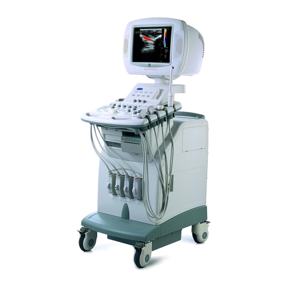
General Description System Characteristics The DC-6/DC-6T/DC-6Vet Diagnostic Ultrasound System is a color Doppler system with features of all-digital architecture and whole-body application, which is designed based on clinical needs. The system supports a wide range of transducers, and its imaging modes include B Mode, M mode, Pulsed Wave Doppler (PW), Continuous Wave Doppler (CW), Color, and Power, Smart3D, iScape and Free Xros M. -
Page 20: System Overview
System Overview System Appearance 2.1.1 Complete System with CRT Monitor... - Page 21 System Overview Name Function <1> Monitor Displays the images and parameters during scanning <2> Minor panel Human-machine interface, operation control <3> Main panel Human-machine interface, operation control <4> Keyboard Human-machine interface, operation control <5> DVD-R/W Rewritable CD drive <6> Space placing Used for placing B/W video printer video printer...
-
Page 22: Complete System With Lcd Monitor
System Overview <18> Power switch Used for turning on/off the power supply 2.1.2 Complete System with LCD Monitor Name Function <1> Monitor Displays the images and parameters during scanning <2> Monitor support arm Supports and adjusts height and position of LCD monitor <3>... -
Page 23: Lcd Monitor
System Overview LCD Monitor... -
Page 24: Brightness And Contrast Buttons
System Overview 2.2.1 Brightness and contrast buttons In the figure at the right side, 1> and <2> are brightness-adjusting buttons, above which is a sun symbol. A “-” symbol above the <1> button indicates the button is used to decrease brightness. A “+” symbol above the <2>... -
Page 25: Up/Down Adjusting Lever
System Overview 2.2.2 Up/down adjusting lever lever left right As shown in the figure above, the lever is located at the lower left of the monitor back. Only when the lever is placed in the rightmost position can it be used for up/down adjustment of the monitor. -
Page 26: Lever Of Upper Support Arm
System Overview 2.2.3 Lever of upper support arm... -
Page 27: I/O Panel
System Overview I/O Panel <13> <17> <1> <9> <2> <5> <10> <14> <18> <3> <6> <11> <15> <19> <7> <12> <16> <20> <4> <8> Symbol Function <1> Used for system recovery <2>, <3> Ethernet interface (<2> is reserved for future use;... -
Page 28: Power Panel
System Overview Power Panel <1> <3> <5> <4> <2> Name Function <1> Ground terminal Used for grounding connection <2> Equipotential terminal Used for equipotential connection <3> Power outlet Power supply for optional peripheral devices <4> Circuit breaker Used for cutting off power supply of the system <5>... -
Page 29: Ecg Panel
System Overview ECG Panel Name Function <1> ECG lead signal input Used for connecting ECG leads and acquiring interface ECG signals <2> External signal Used for connecting the signal output port of input port ECG monitor <3> Footswitch interface Used for connecting the footswitch 2-10... -
Page 30: Control Panel
System Overview Control Panel 2.6.1 Main panel English Name Function <1> Patient Press to start an exam of a new patient. <2> Info Press to enter the patient information input screen. <3> Power indicator Hard disk indicator <4> <5> Toggle to adjust the size of sample volume. <6>... - Page 31 System Overview <14> Color Steer Toggle to adjust ROI steering angle of a linear transducer in the Color/Power mode. <15> Focus Toggle to adjust focus position for B images. <16> Toggle to select IP for B images. <17> Freq/THI Toggle to adjust the current transducer frequency and harmonic frequency.
- Page 32 System Overview <39> Confirms an operation, equivalent to the left-button of the mouse. <40> Caliper Starts general measurement function. <41> Print Prints the screen image (video print control). <42> Trackball Adjusts the cursor’s position on the screen. <43> Arrow Adds comment arrows, and the arrow orientation is adjusted through the multifunction knob.
-
Page 33: Minor Panel
System Overview 2.6.2 Minor panel English Name Function <1> Reserved for future use, can be defined <2> Reserved for future use, can be defined <3> Reserved for future use, can be defined <4> Reserved for future use, can be defined <5>... -
Page 34: Keyboard
System Overview 2.6.3 Keyboard Ejection of the keyboard Push the edge of the keyboard inward slightly, and then the keyboard automatically ejects outward. At this time the light under the main control panel is bright automatically to lighten the keyboard. Retraction of the keyboard Push the keyboard inward, and when a click sound is heard, the keyboard is retracted. - Page 35 System Overview Functions of the keys Function Receiving the input data; or moving the cursor to the head of <1> Enter next row of the text or the input field. <2> Same as that of the『Exit』key <3> Jumping to the next operation <4>...
- Page 36 System Overview Functions of the keys F1 to F12 Function <1> <2> Quickly starting the patient information screen (identical to the 『Info』 key) <3> Quickly starting the diagnosis report screen (identical to the 『Report』 key) <4> Quickly starting the comment status (identical to the 『Comment』...
-
Page 37: Symbols
System Overview Symbols This system uses the symbols listed in the following table, and their meanings are explained as well. Refer to “Safety Precautions” for safety symbols. Symbol Meaning Type-BF device Refer to relevant content in the Operation Manual, to avoid safety accidents Dangerous voltage AC (alternate current) - Page 38 System Overview System reset Audio signal Microphone input jack Product serial number Manufacture date Manufacturer 2-19...
-
Page 39: Principle Description
Principle Description Electric Principle of the System The system consists of transducer module, transmission module, reception module, CW module, beamformer module, B/M-mode signal processing module, color flow signal processing module, Doppler signal processing module, DSC module, CPU system, ECG module, and input/output module, etc. Transducer Transmission Amplifier... -
Page 40: Principle Of Boards
Principle Description Principle of Boards 3.2.1 Transducer Board The block diagram of the transducer board is shown as follows: The transducer board is designed for switching between the transducers and recognition of the transducer IDs. The transducer switching signal controls the relays to switch between the transducers, and the ID reading circuit is independent of the transducer switching circuit and can read out the IDs of the transducers. -
Page 41: Transmission Board
Principle Description represents A, B or C) signal to select the corresponding transducer. Since the system may read multiple transducer ID codes simultaneously, the system software will select the corresponding transducer based on the current exam. When transducers are disconnected or connected, the interrupt signal will be automatically generated to notify the system software, so that the system software can obtain the current status of transducer connection and provide the prompt message accordingly. -
Page 42: Beamformer Board
Principle Description The amplifier board consists of high-voltage isolation circuit, channel select circuit, primary voltage-controlled gain amplification circuit and secondary fixed gain amplification circuit. The control signal of the channel select logic is derived from the beamformer board, and this signal controls the on-off of the reception channel. -
Page 43: Dsp Board
Principle Description At the same time the data is sent to FPGA U59 for color flow signal processing and partial Doppler signal processing. Subsequently part of data is sent to FPGAU83 for remaining color flow signal processing, and the other part of the data is sent to DSP U78 for remaining Doppler signal processing. - Page 44 Principle Description The USB interface HDD can be realized. Display module 3.2.5.4 Processing of graphic and image integration and provision of control interface for main CPU to graphic memory The graphic memory is directly accessed by CPU. Interface control of video input and output CPU system 3.2.5.5 The CPU system is the control core of the ultrasound system, consisting of hardware...
-
Page 45: System Motherboard
Principle Description 5V power indicator ISP1161 test output indicator -5V power indicator D31-D34 Connection indicator network control D8,D14,D15 FPGA debugging indicator D37,D39-D41 FPGA debugging indicator D9,D10,D25 ISP1561 USBVBUS Cine FPGA configuration indicator status indicator D11,D18,D36 Cine FPGA debugging D42-D44 ISP1583 Suspending indicator status indicator... -
Page 46: Cw Board
Principle Description I/O interface definition of the system motherboard: Category Interface Socket number Interfaces with Hard-wired Connecting transmission board, amplifier boards board, beamformer board, DSP board, and the board reserved Transducer Hard-wired Transducer signal connecting board power signal ECG module Soft-wired 2 serial ports footswitch... -
Page 47: Built-In Pc Module
Principle Description Result Transmit Transmit Transmit display converter beamformer Tissue Signal Waveform process generator Reception RF amp Quadrat Reception Audio filter beamform convert converter demo Transmission 3.2.7.1 The transmission signal flow graph is shown as follows: Reception 3.2.7.2 The reception signal flow graph is shown as follows: The high voltage isolation circuit is used to protect the reception circuit. - Page 48 Principle Description purpose of analysis, such as 3D imaging. In the figure below, the broken line stands for control flow, while the real lines stand for data streams. The main CPU control communicates with the built-in PC via a serial port. The built-in PC initiates USB2.0 main control of the PC system and USB2.0 slave of the ultrasound system.
- Page 49 Principle Description Interface definition 3.2.8.3 The ZPACK110 socket is used for connecting the PC carry board and mother board, and signals are defined as follows: 3-11...
-
Page 50: Io Module
Principle Description Model: 110Pin PC platform SIG.DES SIG.DES SIG.DES SIG.DES SIG.DES PA.1 PB.1 DM-SIG PC.1 DP-SIG PD.1 PE.1 VBUS-SIG PA.2 PB.2 DM-PC2 PC.2 DP-PC2 PD.2 PE.2 VBUS-PC2 PA.3 VBUS-PC1 PB.3 DM-PC1 PC.3 DP-PC1 PD.3 PE.3 PA.4 PC-YIN PB.4 PC-CIN PC.4 PD.4 PE.4 PA.5... -
Page 51: Ecg Module
The ECG module communicates with the main CPU system through the RS232 serial port. The ECG signal can be inputted to the system, through an interface compatible with Mindray’s monitoring products. 3-13... -
Page 52: Control Panels And Keyboard
Principle Description ECG lead Front DSC module Amplifier Filter Sampling interface DC IN board Footswitch System detect control ECG module Main CPU system 3.2.11 Control panels and keyboard The control panels and keyboard are designed for key scanning, indicator control, buzzer control, receiving and processing for encoder data, STC data, PS/2 data, and they communicate with the main unit through serial ports. -
Page 53: Detection Board Of Power Output
Principle Description 5V/3.3V DC/DC 4 independent DC/DC rotary encoder converter keys converter 74HC14 enclosure protective earth EPM570T144 adjustment (8- 65-key matrix ATmega64L segment) RS232 serial serial 74HC373 comm level interface converter rotary encoder LED drive/control buzzer knob value The keyboard plays an important role in information communication between the ultrasound system and environment, and on the basis of functions it consists of: CPU circuit, DC/DC conversion circuit, key control circuit, trackball control circuit, encoder control circuit, LED drive circuit and STC A/D sampling circuit. -
Page 54: Crt Monitor
Principle Description The block diagram of the detection board is shown as follows: voltage HPV1 follow lowpass +D5V divider voltage -HPV1 backward lowpass POWER divider -A5V -A5V voltage HPV2 follow lowpass divider AD7928 voltage -HPV2 backward lowpass divider CON1 CON2 ADT7516 VREF CON3... -
Page 55: Lcd Monitor
Principle Description 3.2.14 LCD monitor Components of LCD monitor module 3.2.14.1 LCD module consists of 15 inch LCD display screen, boards and cards, wires and metal parts. The components of the LCD module are shown as follows: Components Name 15 inch TFT LCD PANEL-LQ150X1LW71N 15 inch LCD control board- LQ150X1LW71N 15 inch LCD LVDS connecting wire Connecting wire between 15 inch LCD power board... - Page 56 Principle Description Function diagram 3.2.14.2 15" LCD panel CCFL LVDS Speaker(left) Speaker(right) Audio R +/- Audio L +/- Inverter & Power LCD drive Signal , 12v Key OSD board Toggle switch AC 90-260V Audio L/R Light board Auxiliary output IO interface board AC 90-260V Interface definition 3.2.14.3...
-
Page 57: Power Supply Principle
Principle Description RX3- RX1- RX3+ RX1+ Definition of speaker signal pins: PIN NUMBER SIGNAL L-SDBX+ L-SDBX- R-SDBX+ R-SDBX- Definition of VGA signal pins: PIN NUMBER SIGNAL VSYNC HSYNC BLUE GREEN Definition of AC input pins: PIN NUMBER SIGNAL Power Supply Principle 3.3.1 Power supply system The power system consists of connecting board, PFC board, +5V board, -5V board, PHV 3-19... - Page 58 Principle Description board, adapter board of auxiliary output, LED board, adapter board of fans, power motherboard and detection board of power output. The AC line power passes the circuit breaker to enter the connecting board, and then, through the isolation transformer, two isolated outputs are obtained. After filtered, one output serves as AC auxiliary output for the monitor and printers, the other passes the power motherboard to become the input power for the PFC board.
- Page 59 Principle Description 隔隔隔隔隔 isolation transformer LED 指指连 LED indicator board 彩彩黑黑 color video Connecting 打打打 printer board 风风连连连 connecting board auxiliary 辅辅辅辅 output adapter 转连连 board 黑黑黑黑 B/W video 打打打 printer 显指隔 monitor PFC board POFF POFF CON(1~4) POFF System +5V board motherboard +3.3V...
-
Page 60: Principle Of Power Boards
Principle Description 3.3.2 Principle of power boards Connecting board 3.3.2.1 The block diagram of the connecting board is shown as follows. The line power input passes the circuit breaker to enter the connecting board, passes the surge current rejection circuit to reach an isolation transformer, and then the isolation transformer generates two AC outputs which are isolated with the line power. - Page 61 Principle Description Besides OVP and OTP, the PFC board receives the fail protection signal PF from the +5V board, the soft turn-off signal POFF and turn-off enable signal ENA, thus realizing the safe turn-off of the entire power system. The core ICs of the PFC board, PFC controller and PWM controller, are respectively UC3854 and 38HC43 made by TI.
- Page 62 Principle Description secondary FORWARD auxiliary power converter supply Input filter +5V/30A output Active clamp +5V/+3.3V BUCK feedback converter board +3.3V/30A output control optocoupler isolation (feedback) PF signal optocoupler PF signal isolation circuit (feedback) -5V board 3.3.2.4 The -5V board adopts the structure of single-end forward converter, and its block diagram is shown as follows.
- Page 63 Principle Description FORWARD transformer magamp -12V output rectifier adjustment filter input 390Vdc filter power circuit board PFL signal overcurre ocp/ovp signal nt & over- voltage detection magamp -5V output rectifier adjustment filter power control motherboard +12V output rectifier filter OVP& feedback optocoupler isolation...
-
Page 64: System Software
Principle Description Other boards 3.3.2.6 The principle of other boards is simple and all components on the boards are almost passive, so it isn’t necessary to describe it. System Software 3.4.1 Structure The system software consists of hardware interface layer, medium support layer and upper software layer. -
Page 65: Principle
Principle Description 3.4.2 Principle The entire software system runs through asynchronous processing mechanism of message control. Commands are entered through GUI system and control panel, and stored in mailboxes, so that the software system can obtain the commands from the mailboxes to interpret and execute. -
Page 66: Exploded View Of Complete System
System Structure Assembly/Disassembly Exploded View of Complete System... - Page 67 System Structure and Assembly/Disassembly Part Number Name Part Number Name 2105-20-40185 monitor tail cover 2105-30-40252 DVD assembly (optional) 2105-20-40184 monitor rear cover 2105-20-40159 VCR cover plate 2105-20-40198 Up/down pin roll 2105-30-40376 VCR assembly (optional) 2105-30-40392 Monitor supporting 2105-20-40120 R1000 transformer and moving (1000VA) assembly...
-
Page 68: Exploded View Of Lcd Monitor And Support Arm
System Structure and Assembly/Disassembly Exploded View of LCD Monitor and Support Arm Part Number Name Part Number Name 2111-30-73327 Base assembly 6200-10-09762 Ground wire strip Lower support arm 2111-20-73283 043-000395-00 Upper support arm cover Press block of 2111-20-73313 upper support arm 2111-20-73285 Rubber cover gyration... -
Page 69: Disassembly And Replacement
System Structure and Assembly/Disassembly Disassembly and Replacement 4.3.1 Disassembly of the monitor Disassembly of CRT monitor 4.3.1.1 Remove the monitor tail cover and minor panel rear cover, and rotate the monitor 90° clockwise, and remove the neck cable cover. 90° Monitor assembly Monitor tail cover M4X12 screw... - Page 70 System Structure and Assembly/Disassembly 90° Monitor tail cover Neck cable cover M4X12 screw Loosen the screws fixing the monitor in two sides and back side, remove the monitor assembly, put the cables inside the keyboard assembly, and install the minor panel rear cover. Monitor assembly Keyboard assembly Minor panel rear cover...
- Page 71 System Structure and Assembly/Disassembly Toggle the lever to tilt the monitor to the horizontal position (refer to Chapter 2). 3) Remove the wire strip screws and cable connector, and remove the six screws fixing the monitor. 4) To remove the LCD monitor from the support arm, lift it first and then disconnect it from the hook.
- Page 72 System Structure and Assembly/Disassembly Tilt the monitor to the position as shown in the figure, and hold it by two sides and lift it in the direction of F, until it is disconnected. Adjust the LCD monitor after changing or replacing the main board: Follow step 1, 2 and 3 in section 7.2.3.1 to enter the System Maintenance Menu and select the Monitor Test item.
-
Page 73: Replacement Of The Bottom Light
System Structure and Assembly/Disassembly jitters for about 5s before you can switch the screen. Press the right direction key on the minor keyboard to display the following screen. Select “autocolour” on the upper screen, the color changes for 5s before you can select “exit”... -
Page 74: Replacement Of Spring Damping Parts
System Structure and Assembly/Disassembly Light Transparent cover M3X8 countersunk screw Replacement of LCD monitor bottom light is described as follows: a) Swivel the monitor to one side of the machine (as shown in the figure below); b) Remove two M3X8 countersunk screws to remove “transparent cover”. c) Remove the old lamp and replace it with new one. - Page 75 System Structure and Assembly/Disassembly 1. Upper support arm cover 4) Press the upper support arm, and remove the screw pins and the M5 spring washers with a Philips screwdriver; 1. Screw pins & M5 spring washer 2. Upper support arm 5)...
- Page 76 System Structure and Assembly/Disassembly 1. Retainer ring 6) Hold the support arm to lift it and push the cross-pin out from one side. 1. Cross-pin of the upper support arm NOTE: 1. Make sure the upper support arm is turned upward to the extreme position before pushing the cross-pin out.
- Page 77 System Structure and Assembly/Disassembly 7) Extract the upper support arm along the pilot sleeve and extract the spring from the pilot sleeve. 1. Pilot sleeve of the spring 2. Spring 8) Remove the retaining nuts of the rubber damping pole and then remove the rubber damping pole from the end of the pilot sleeve.
- Page 78 System Structure and Assembly/Disassembly 1. Pilot sleeve of the spring 2. Rubber damping pole 3. Retaining nuts of the rubber damping pole Tips: After assembling the support arm (including the monitor), check whether the monitor stays still at a random height. If not, adjust the tightness of the spring by screwing the adjusting nut with a screwdriver until the monitor stays still at a random height and then fix the upper support cover.
-
Page 79: Disassembly Of The Main Panel
System Structure and Assembly/Disassembly 1. Adjusting nut of the spring 4.3.4 Disassembly of the main panel Remove the three holders on the right side of the main panel. Holder Remove three M3x8 screws on the side of the main panel assembly and five M4x12 screws at the bottom (The figure below doesn’t show the main unit but shows the positions of the screws.) 4-14... - Page 80 System Structure and Assembly/Disassembly Five M4X12 screws Three M3X8 screws Draw out the handle of the main panel. Main panel assembly Lift the front end of the main panel, and disconnect the cables, and take out the main panel. 4-15...
-
Page 81: Disassembly Of The Minor Panel
System Structure and Assembly/Disassembly 4.3.5 Disassembly of the minor panel Remove the main panel assembly as per the procedures described in section 4.3.4. Loosen the “nondetachable screw”, and remove the minor panel rear cover assembly. Minor panel rear cover Nondetachable screw 4-16... - Page 82 System Structure and Assembly/Disassembly Nondetachable screw The upper arm shall be rotated to the position as shown in the figure, before the operations above are performed; otherwise, the upper arm will interfere with the disassembly of the rear cover. Remove the two M4x8 screws fixing the sides of the minor panel assembly. Screws fixing the sides Remove the two M4x8 screws fixing the front of the minor panel assembly.
-
Page 83: Replacement Of The Trackball
System Structure and Assembly/Disassembly Screws fixing the front Lift the minor panel assembly upward and take it out. Minor panel assembly 4.3.6 Replacement of the trackball Remove the main panel assembly as per the section 4.3.4. Disconnect the cable of the trackball, remove the fixing screws to take out the fixing bracket, than remove the trackball and replace it with a new one. -
Page 84: Replacement Of The Main Panel Pcba
System Structure and Assembly/Disassembly Screw Fixing bracket Trackball Cable 4.3.7 Replacement of the main panel PCBA (1) After the step 4.3.6 is completed and the trackball is removed, pull out the knobs from the panel by hand. Knob 4-19... - Page 85 System Structure and Assembly/Disassembly (2) Turn over the main panel assembly, loosen the fixing plate and fixing screws of encoders, and remove the fixing plate and encoders. Fixing screws Fixing plate Encode 4-20...
- Page 86 System Structure and Assembly/Disassembly (3) Loosen the fixing screws of the encoder PCBA and main panel PCBA, and remove the encoder PCBA and main panel PCBA, and replace it with a new one. Main Fixing screws Encoder PCBA panel PCBA (4) Remove silicone keys from the main panel PCBA: The silicone keys are installed in the main panel PCBA through the locating poles of the keys and the corresponding locating holes in the panel...
-
Page 87: Replacement Of The Keyboard Pcba
System Structure and Assembly/Disassembly Locating pole Silicone key Locating holes Main panel PCBA 4.3.8 Replacement of the keyboard PCBA Remove the keyboard assembly as per the section 4.3.5. Pull out eight STC DIP switches, two encoder knobs and one double-layer knob. STC DIP switch Encoder knob Double-layer knob... -
Page 88: Replacement Of The Keyboard
System Structure and Assembly/Disassembly Remove the four screws, pull out encoder cable and take out the encoders. Screw Encoder Remove the self-threading screws and grounding screw, remove the grounding wire, and take out the keyboard PCBA for replacement. Grounding wire keyboard PCBA Grounding screw... - Page 89 System Structure and Assembly/Disassembly Keyboard assembly ② ① After the keyboard assembly ejects in position, as shown in the figure (seen from the back surface), use two hands simultaneously to toggle the two plastic rods at the first nodes of the slide tracks on the back surface of the keyboard assembly (squat down if necessary), and slightly pull out the keyboard assembly;...
-
Page 90: Replacement Of The Light Control Pcba
System Structure and Assembly/Disassembly c) Loosen the screw (M4X12) on the keyboard connector clip, and remove the cable joint of the keyboard to take out the keyboard. Slide track Screw on the keyboard Slide track connector clip Fixing screw of slide track d) Remove the fixing screws (4 M4X8 panhead screws with washers) of remaining slide tracks and keyboard support, and install the slide tracks to the new keyboard... -
Page 91: Replacement Of The Keyboard Slide Tracks
System Structure and Assembly/Disassembly Main panel assembly Light control PCBA Socket b) Use a screwdriver to remove two screws fixing the light control PCBA (2 M4X8 screws), remove the light control PCBA and replace it with a new one, and install the new PCBA. -
Page 92: Replacement Of The Snap-Close (Lock Head And Lock Seat)
System Structure and Assembly/Disassembly 13 M4x12 screws After the keyboard ejects completely, remove the four screws fixing the slide tracks (4 M3X8 screws) to take out the keyboard assembly and slide tracks. Disassemble the slide tracks from the keyboard assembly, replace them with new tracks and install on the keyboard assembly. - Page 93 System Structure and Assembly/Disassembly Install the new lock seat properly. Screws fixing lock seat Magnify Lock seat Replacement of the lock head 4.3.12.2 The procedures are identical to section 4.3.9 a, b, and c (replacement of keyboard assembly). After removing the keyboard assembly, remove the screws fixing the lock head (2 M3X8 screws).
-
Page 94: Replacement Of The Travel Switch (With The Cable)
System Structure and Assembly/Disassembly Screws fixing lock head Lock head 4.3.13 Replacement of the travel switch (with the cable) Remove the main panel assembly and minor panel assembly (see section 4.3.4 and section 4.3.5), and remove the fixing screws of the cast-aluminum cover to take out the cast-aluminum cover. -
Page 95: Disassembly Of The System Boards
System Structure and Assembly/Disassembly 4.3.14 Disassembly of the system boards Layout of the system boards Amplifier board Transmission board CW board Beamformer board DSP board PHV board -5V board +5V board PFC board 4-30... - Page 96 System Structure and Assembly/Disassembly Press down the brakes of the casters 4.3.14.1 Note: Brake the system immediately when it isn’t necessary to move it. Press down the brakes. Remove the screw caps, screws and rear cover 4.3.14.2 Remove 10 screw caps of the rear cover. Remove 13 M4×8 screws connecting the rear cover and the main unit housing.
- Page 97 System Structure and Assembly/Disassembly 10 screw caps 13 M4×8 screws Rear cover assembly 4-32...
- Page 98 System Structure and Assembly/Disassembly Remove IO assembly 4.3.14.3 Remove the cables from the IO panel, i.e., remove the connectors from the IO interfaces. Care shall be taken to avoid damage of the cables. cables 4-33...
- Page 99 System Structure and Assembly/Disassembly Remove the two rows of M3x8 screws fixing the IO assembly, hold the two grips by hands, and take out the IO assembly. If a built-in PC module is installed, you shall disconnect USB and network cables between the PC module and IO assembly. Screws Grips Pull out the card detacher, and remove the boards one by one.
- Page 100 System Structure and Assembly/Disassembly Remove the power boards 4.3.14.4 To remove the auxiliary output cables and shielding cover of the power main unit box: disconnect the three power connectors of the auxiliary output assembly; Remove six M3X8 screws fixing the shielding cover of the power box. Screws Power shielding...
- Page 101 System Structure and Assembly/Disassembly Power boards Card detacher 4-36...
-
Page 102: Remove Built-In Pc Module
System Structure and Assembly/Disassembly 4.3.15 Remove built-in PC module a) Repeat section 4.3.14.1 to push down the brake to lock up the casters. b) Repeat section 4.3.14.2 to remove screws and rear cover. c) Repeat steps a and b in section 4.3.14.3 to remove wires of IO panel, and to remove IO panel;... - Page 103 System Structure and Assembly/Disassembly e) Remove 13 M3X8 screws fixing cover plate and wire connectors, and remove the cover plate and bale of wire between 3D module and IO board. M3X8 screws cover plate f) Disconnect the wire connector of the fan from the PC carry board, remove the four M2.5X6 screws fixing the radiator, and then remove the industrial control main board from the PC carry board.
- Page 104 System Structure and Assembly/Disassembly g) Disconnect wires from the PC carry board, remove 8 M3X8 screws, and take out the PC carry board. M3X8 screws PC carry board i) Disconnect the wires behind HDD, remove four M3X8 screws fixing the bracket, and remove the HDD.
-
Page 105: Remove Hdd
System Structure and Assembly/Disassembly j) Remove four M3X8 screws in the HDD bracket in order to replace HDD. M3X8 screws 4.3.16 Remove HDD After removing the IO assembly, disconnect the HDD power cable and signal cable, then remove HDD bracket and 4 M3x8 screws fixing IO shielding cover, and remove HDD and its bracket. -
Page 106: Remove The Dvd-R/W Assembly
System Structure and Assembly/Disassembly Remove 4 screws fixing the HDD in its bracket to take out the HDD. 4 screws 4.3.17 Remove the DVD-R/W assembly Remove the DVD-R/W cover: Press down the two buckles on the CD/RW cover, and draw it out at an angle to take out the DVD-R/W cover. - Page 107 System Structure and Assembly/Disassembly Remove the DVD-R/W assembly (1) Remove the two M4×8 screws fixing the DVD-R/W assembly and main unit housing. 2 M4×8 screws (2) Remove the DVD-R/W assembly, and remove the power cable and signal cable. Signal cable DVD-R/W assemb Power cable...
-
Page 108: Remove The Ecg Assembly
System Structure and Assembly/Disassembly Remove DVD-R/W: remove 4 M3x8 screws at the bottom of the DVD-R/W to take out the DVD-R/W DVD-R/W DVD-R/W bracket 4 M3x8 screws 4.3.18 Remove the ECG assembly Remove the footplate. (1) Remove 3 M4×8 screws at the bottom of the footplate assembly. (2) Draw out the footplate assembly. - Page 109 System Structure and Assembly/Disassembly Remove the front cover of the main unit. (1) Remove 6 screw caps on the left and right side plates (3 on each side). (2) Remove 6 M4×8 screws (3 on each side). 6 M4×8 screws 6 screw caps (3) Remove 4 M4×8 screws at the bottom of the front cover assembly of the main unit.
- Page 110 System Structure and Assembly/Disassembly Remove the cable of the ECG assembly. Cable of ECG footswitch Remove 4 M4 × 8 screws of the ECG assembly, pull it up until the ECG assembly is detached from the main unit housing, and remove the ECG assembly. Hook of the ECG assembly.
- Page 111 System Structure and Assembly/Disassembly Remove the M3X8 screw, disconnect the cables, and remove the ECG base assembly and ECG mounting cover. M3X8 screw ECG mounting cover ECG base assembly Remove M3X8 screws, and replace the ECG board or footswitch connecting PCBA.
-
Page 112: Remove The Transducer Board
System Structure and Assembly/Disassembly 4.3.19 Remove the transducer board Remove the transducer assembly: remove 22 M3x8 screws fixing the transducer assembly and main unit, hold the two grips to draw out the board; care shall be taken to avoid damage of interior connectors. 22 M3x8 screws Grips... - Page 113 System Structure and Assembly/Disassembly 19 M3x8 screws Shielding cover of the transducer board M3x8 screws Remove 6 M3x8 countersunk screws fixing the shielding frames and shielding plates of the transducer sockets, and remove the shielding frames of the transducer, 3 in total (do not remove the pseudo transducer at the leftmost); Shielding frame Pseudo transducer Shielding plate...
-
Page 114: Replace The Inlet Dust Net
System Structure and Assembly/Disassembly Remove 2 M3X8 countersunk screws for each transducer mounting bracket and shielding plate, remove 2 M2.5X8 panhead screws for the transducer socket and transducer mounting bracket, and remove the transducer mounting brackets (6 in total). M2.5X8 panhead screw M3X8 countersunk... - Page 115 System Structure and Assembly/Disassembly Loosen nondetachable screws Inlet dust net Move the dust net support to the side until it is detached from the hook, and take out the net support. Move the dust net Inlet dust support to the side support Dust net &...
-
Page 116: Remove The Transformer
System Structure and Assembly/Disassembly Replace the net and the net support with new ones. Net and support 4.3.21 Remove the transformer Remove the inlet dust net as per the step a in section 4.2.18. Remove 4 M3x8 screws of the separating plate of the transformer, and take out the separating plate. -
Page 117: Remove The Fan Assembly
System Structure and Assembly/Disassembly bottom of the right side), draw out the transformer from the left side, disconnect the input and output cables of the transformer, and take out the transformer. Cables 4 M5x10 inner hexagonal screws 4.3.22 Remove the fan assembly Remove the inlet fan of the power main unit box. - Page 118 System Structure and Assembly/Disassembly Remove the main unit rear cover. Remove 2 M3×8 screws of the inlet fan assembly. Hold the grips, and draw out the outlet fan assembly. Outlet fan M3X8 screw Remove the inlet fan of the system main unit housing. Remove the main unit rear cover.
- Page 119 System Structure and Assembly/Disassembly Inlet fan 2 screws Remove the outlet fan of the system main unit housing. Remove the main unit rear cover. Remove 2 screws fixing fan frame. Hold the grips, and draw out the outlet fan assembly. Outlet fan 2 screws 4-54...
-
Page 120: Replace Casters
System Structure and Assembly/Disassembly 4.3.23 Replace casters Brake the two casters which aren’t to be replaced (front or rear). Place a jack (maximum load: over 100 kg) in the mounting area of casters, and lift the two casters at the same time, thus the system doesn’t topple to one side. - Page 121 System Structure and Assembly/Disassembly M8 washer 4 M8×16 screws Put washers on the new casters and use a torque wrench to tighten the casters. Torque: 15 N m If the torque wrench isn’t available, apply a force of 75 N to the wrench in the position 20 cm away from the axis of rotation.
-
Page 122: Installation Of Peripherals
System Structure and Assembly/Disassembly Installation of Peripherals 4.4.1 Installation of black/white video printer Remove 4 M3X8 cross panhead screws and 1 M4X8 cross panhead screws from the bracket. Note: the five screws mentioned above are all on the bracket of the printer for use. Use the 4 M3X8 cross panhead screws to fix the printer and the bracket. - Page 123 System Structure and Assembly/Disassembly Connect the power cable, control cable, and signal cable reserved in the peripheral bay to the printer Control cable Signal cable Power cable Place the printer inside the peripheral space, lift it slightly to grab it (to avoid slippage of the printer), and tighten the M4X8 screws for the video printer and the main unit.
-
Page 124: Installation Of Color Video Printer
System Structure and Assembly/Disassembly 4.4.2 Installation of color video printer There are two steps for installation of the color printer: 1) installation of the printer cables; 2) installation of the color printer. The optional printers are of two models: 1) Sony UP-20; 2) MITSUBISHI CP-910E printer. - Page 125 System Structure and Assembly/Disassembly Remove 2 screws fixing the fixing bracket and remove the fixing bracket. Fixing bracket Mounting bracket Screw Open the plastic bag to take out the four M5×25 screws, and install the mounting bracket on the system. (Note: the side which has screw thread shall face to the left side of the system.) Inner hexagonal...
- Page 126 System Structure and Assembly/Disassembly Use the screws to fix the printer on the fixing bracket. Note that the side which has holes shall face to the front of the printer. Fixing bracket M3X8 screw Place the fixing bracket on the mounting bracket, and push it inside the mounting bracket.
- Page 127 System Structure and Assembly/Disassembly Connect the signal cable and power cable. For S-Video out cable For REMOTE cable Connection of signal cables of the color printer For power cable 4-62...
-
Page 128: Installation Of Vcr
System Structure and Assembly/Disassembly 4.4.3 Installation of VCR First confirm the configuration of the VCR’s DIP switches. • SONY SVO-9500MD (ON, OFF) baud rate 9600 bps (OFF) (OFF) (OFF) (OFF) Remove the two side covers of VCR. VCR side cover 4-63... - Page 129 System Structure and Assembly/Disassembly Take out the VCR mounting bracket from the package, and remove the screws fixed on the mounting bracket. M3X8 screw M4X8 screw VCR mounting bracket Fix the VCR using four screws. M3X8 screw 4-64...
- Page 130 System Structure and Assembly/Disassembly Push the VCR and bracket into the peripheral bay, ensuring that the two elbows below the mounting bracket insert to the two bridges of the housing, and the other side is fixed by two M4×8 screws. Two bridges of the housing Elbow...
- Page 131 System Structure and Assembly/Disassembly Connect the power cable and signal cable (to alternative of S VIDEO connectors). The audio IN/OUT and S VIDEO IN/OUT cables are integrated into one strand of cables for the VCR module. VCR serial port S VIDEO output S VIDEO input Audio input Audio output...
-
Page 132: Maintenance Requirements
Maintenance Requirements Tools Required 5.1.1 Tools/measurement devices and consumables Table 5-1 Tools and measurement devices Tools/measurement devices Quantity Remarks Resin or stainless steel container Large enough to accommodate two transducers Approx. 2 m × 2 m (0.3 mm Plastic bags thickness) Vacuum cleaner Makita 4014NV or equivalent... -
Page 133: Standard Configuration Of Tools And Consumables
Maintenance Requirements WARNING: Do not use solvents (such as paint thinner or benzine) or abrasive cleansers for cleaning the system. These substances may cause deterioration in the system. 2. . . . Do not use hydrocarbon glass cleaner or cleaner for the OA equipment to clean the monitor. -
Page 134: Maintenance Personnel
Paper file (various types) Ethanol for cleaning and disinfection Maintenance Personnel To ensure the performance and safety of the system, the maintenance personnel shall be technical professionals from Mindray or engineers who have been trained and have capability of maintenance for this system. -
Page 135: Checks
Inspection Schedule Model Remarks 6 months after installation 12 months after installation DC-6/DC-6T 6.1.2 Checks before inspection Check the system conditions 6.1.2.1 Check the items below together with the user, thus confirming the system conditions. Check: Any abnormality while the system is in operation;... -
Page 136: Function Checks
Checks version. Check the system operation 6.1.2.5 Check that the menus and windows can pop up normally. Check that measurements can be performed in each exam mode, such as OB measurements and cardiac measurements, etc. Check that exam modes can be normally switched. Check that display modes can be normally switched. - Page 137 Checks Checking the initial operations Check the functions of each MODE key. Check and print out the images obtained by every transducer. Check the functions of the peripheral devices. Checking general operations Check that the Freeze key can freeze or unfreeze an image. Check that the gain key can normally work.
-
Page 138: Safety Checks
Checks Safety Checks 6.3.1 Electric safety Refer to Appendix D Electrical Safety Inspection. -
Page 139: Checks For Mechanical Safety
Checks 6.3.2 Checks for mechanical safety Evaluation: execute the evaluation by means of visual check and operating checks • Flowchart for checks Check casters ↓ Check caster connection ↓ Check the handles ↓ Check the control panel support ... - Page 140 Checks item check content procedure tool 1) Check the casters by eyes to confirm that there is no skewness, connecting screws are free of breakage or falling off. Caster connection 2) Use a wrench to check that the Inner connecting screws hexagonal casters and the base are free...
- Page 141 Checks item check content procedure tool 4) Remove the rear cover of the Philips control panel and neck cover screwdrive of the monitor, check by a inner wrench to confirm that the hexagonal fixing screws are free of looseness; check by eyes to wrench confirm that the cables are free of scratch.
-
Page 142: Image Checks
Checks Image Checks 6.4.1 B/W image phantom data checks and image records System setups 6.4.1.1 The user-defined setups are adopted for all the setups which aren’t mentioned in this manual. For the setups changed due to special reasons, they shall be recorded as added information. Image records and archives 6.4.1.2 The printed images shall be archived with the recorded data. -
Page 143: Final Operation Checks And Image Archive
Print the images and archive the images. 6.4.4 Checking color flow images The service engineers shall be trained by Mindray’s professionals, and the method is to use a transducer to examine and capture a color carotid flow image. The color flow image shall be evaluated depending on whether the flow is full, whether there is an artifact or overflow, and whether the edge is smooth. -
Page 144: System Maintenance
System Maintenance Cleaning 7.1.1 Flowchart for cleaning Unplug the power plug from the wall outlet ↓ Remove the accessories ↓ Remove the housing of the main unit ↓ Clean interior of the system and fan ↓ Clean covers and control panels ... - Page 145 System Maintenance Put the nozzle of the vacuum cleaner into the plastic bag, and turn on the vacuum cleaner to vacuum dust. Cut an opening at the top of the plastic bag to insert the pipe of the blower. Then use the blower to clean the dust of the main unit.
- Page 146 System Maintenance Clean the two long shafts, the bearing and the rotary ball with clean soft dry cloth or paper. Bearing Long shaft Long shaft c)Installing the trackball Put the rotary ball back in the trackball and then align the clamping ring click with the top cover notch.
-
Page 147: Software Maintenance
System Maintenance Software Maintenance Note: If power is off during upgrading process, the upgrading operation will fail and the system cannot be reset. 7.2.1 Back up the preset data Prior to software maintenance, confirm that all relevant data must be those used in this system;... -
Page 148: Restore The Preset Data
System Maintenance After the Set key is pressed, a dialog box appears; select the storage path and enter a filename, as shown in the figure below: Click the OK button, and the backup of preset data is completed. 7.2.2 Restore the preset data After the software maintenance is completed, the user must restore the preset data as per the procedures below. - Page 149 System Maintenance Move the cursor onto “Preset Data”, and select “Load”, as shown in the figure below: After the Set key is pressed, a dialog box appears; select storage path and file, as shown in the figure below: Click the OK button, and the loading of preset data is completed.
-
Page 150: Upgrade The Software
System Maintenance 7.2.3 Upgrade the software Upgrade files in batches 7.2.3.1 Enter the preset menu via F10 on the keyboard, as shown below: Select Maintenance and press the Set key; after the dialog box below appears, enter the password. Press OK to enter the Maintenance menu, as shown below:... - Page 151 System Maintenance Select Update and press the Set key to enter the dialog box shown below, and then select the files with suffix TXT in the upgrading file folders on the corresponding driver. Select OK and press the Set key, and then the system starts to upgrade files in batches.
- Page 152 System Maintenance Move the cursor on the Upgrade item, as shown in the figure below: Select the system software item and press the Set button, as shown in the figure below:...
-
Page 153: System Recovery
System Maintenance In the upgraded file folder of the corresponding drive (the corresponding drive of the U disk is G:) , select the files with suffix UPG, and then select OK and press the Set key. The system starts to upgrade the system software. After the upgrading is completed, the following dialog box appears: 5. - Page 154 System Maintenance Follow the steps 1 through 3 in section 7.2.3.1 to enter the maintenance menu and select Config and press Set. The Input Password dialog box appears. Input correct password and press OK to enter the configuration screen. 7-11...
-
Page 155: Hard Disk Recovery
System Maintenance Click the Load Product Symbol button, and the following dialog box appears. Select the corresponding file in the C:\Picture\logo, and click OK. On the Config screen, respectively click the Load Boot Logo and Load Dormancy Image to set the corresponding images. Note: Refer to Appendix C for Initial Data of the Hard Disk. -
Page 156: Install And Uninstall The Software Of Optional Devices
System Maintenance Turn on the machine, and the system will automatically enter recovery. The following message pops up, stating: “Notify: Rescue is successful, please eject rescue disks & dog and then restart. This indicates that the hard disk is recovered successfully. Then restart the system. - Page 157 System Maintenance Click OK button, and the following dialog box appears. Click OK button, and the following dialog box appears. Click OK button, and the installation of DICOM is completed. 4. Uninstall the DICOM In the dialog box for installing and uninstalling the software, select the Uninstall DICOM button and press the Set button, and the following dialog box appears.
-
Page 158: Monitor Test
System Maintenance Click OK button, and the DICOM uninstall is completed. 5. Install and uninstall the HPRF”, “Smart3D”, “iScape” and “Free Xros M” In the dialog box for installing and uninstalling the software, select Install and the corresponding function button and press the Set key, and apply correct KEY file to install the corresponding function software. - Page 159 System Maintenance The evaluating criterion is shown as follows: The monitor shall display the four colors as shown in the figure above. The brightness turns brighter from left to right. After the left arrow key on the lower right part of the keyboard is pressed, and the monitor displays as follows: The evaluating criterion is: the circles and squares displayed on the monitor shall be the same as those in the figure, and no distortion is allowed.
-
Page 160: Self-Test
System Maintenance The evaluating criterion is: the characters and crosses displayed on the monitor shall be the same as those in the figure, which are clearly recognizable. For LCD monitor, you shall perform the test of bright points and dark points. The evaluating criterion is shown as follows: The number of bright points is 0;... - Page 161 System Maintenance Click OK button, and the dialog box of self-diagnosis report appears. Press the Save button to save the self-diagnosis report in the directory of D: \log; if press the Cancel button, the system will not save the self-diagnosis report. The follow dialog box appears.
-
Page 162: Troubleshooting
Troubleshooting Troubleshooting for Power problem possible reason measure When circuit voltage range 1. Check if the voltage is correct. breaker is turned on, incorrect or the primary side 2. Check if the connection wire of it trips. is connected inversely. transformer correctly connected. -
Page 163: Troubleshooting For The Power-Up Process
Troubleshooting problem possible reason measure There is no display on the Due to fault of the Check the power cable. monitor. monitor power. The monitor indicator isn’t There is no display on the Due to fault of the 1. Check the signal cable. monitor. -
Page 164: Troubleshooting For The Operation Process
Troubleshooting Troubleshooting for the Operation Process problem possible reason measure There are minute dark Due to fault of the 1. Replace the transducer. stripes in the near field. transducer. 2. Replace the transmission 2. Due to fault of the board. transmission circuit. -
Page 165: Troubleshooting For Others
Troubleshooting problem possible reason measure After a U disk or USB 1. The model of the 1. The recommended portable HDD is U disk or HDD models shall be used. connected, the icon isn’t supported 2. Under Windows, doesn’t appear at the by the system. - Page 166 Troubleshooting problem possible reason measure There is no response 1. Fault of the 1. Restart the system. from the main panel. software. 2. Replace the power cable of 2. Fault of the power the main panel. cable of the main 3.
-
Page 167: Appendix A Spare Part List
Appendix A Spare Part List Part Number Part Name Quantity Parent module 2105-30-40101 +5V board 2105-30-40108 -5V power board 2105-30-40114 PHV power board 2105-30-40095 PFC board 2105-30-40433 Power output monitor board 2105-30-40365 Power outlet fan assembly 2105-30-40364 Power inlet fan assembly 2105-30-40122 Power motherboard 2105-20-40402... - Page 168 Spare Part List Part Number Part Name Quantity Parent module 2105-30-40594 Mindray-made trackball assembly 2105-20-40347 Encoder cable 2105-20-40350 Cable of the light for the keyboard 2105-20-40353 Cable of functional encoder 2105-20-40354 Cable of Angel encoder 2105-30-40301 Minor panel PCBA 2105-30-40344...
- Page 169 Spare Part List Part Number Part Name Quantity Parent module 2105-30-40305 Keyboard light control board assembly PCBA (2105-30-40388) M07-00100S--- SWITCH breaker 250V 13A 2105-30-40119 Connecting board 2105-20-40286 Connection cable transformer 2105-20-40287 Connection cable transformer 2105-20-40291 AC input cable of connecting Power input board...
-
Page 170: Appendix B Interface Definition And Function List
Appendix B Interface Definition and Function List B.1 System Motherboard B.1.1 Definition of P7 interface between power output board connected to system motherboard Definition Definition +VH1 A-100 -VH1 +VH2 PW-LED -VH2 NPW-OFF NPW-EN A+100 B.1.2 Definition of P8 interface between power output board connected to system motherboard Definition Definition... - Page 171 Interface Definition and Function List Definition Definition -12V A+12V B.1.3 Definition of P9 interface between power output board connected to system motherboard Definition Definition D+5V D+5V D+5V D+5V 3.3V 3.3V 3.3V B.1.4 Definition of P10 interface between power output board connected to system motherboard Definition Definition...
- Page 172 Interface Definition and Function List B.2 Interface definition and function of IO connecting board Interface Definition Interface Definition Interface D+5V J9 reserved for D+12V power cooling cables D+12V fan power D+12V B.3 Interface definition of IO interface board Interface Definition J1 CD power interface D12V D12V...
- Page 173 Interface Definition and Function List Interface Function Reserved for 8.4” touchscreen module VGA signal Touchscreen and keyboard control signal Reserved interface CD signal interface Reserved interface B.5 Power input connecting board Interface definition of P4 main unit Interface power P1 AC P5/P6 Definition Definition...
-
Page 174: Appendix C Initial Data Of The Hard Disk
Appendix C Initial Data of the Hard Disk Disk Directory Directory & Filename Description Symbol 3C5.pod 7L4.pod Transducer data ….. System C6Prn_font_Cn.ttf DC-6 Chinese print font C6Prn_font_Eu.ttf DC-6 Europe print font C6Prn_font_Ru.ttf DC-6 Russian print font DC-6 Comment font C6Comm_font.ttf upgrade files DC-6 French comment C6Comm_font_FG.ttf... -
Page 175: Appendix D Electrical Safety Inspection
Appendix D Electrical Safety Inspection The following electrical safety tests are recommended as part of a comprehensive preventive maintenance program. They are a proven means of detecting abnormalities that, if undetected, could prove dangerous to either the patient or the operator. Additional tests may be required according to local regulations. - Page 176 ELECTRICAL SAFETY INSPECTION 1- Power Cord Plug TEST PROCEDURE The Power Plug The Power Plug Pins No broken or bent pin. No discolored pins. The Plug Body No physical damage to the plug body. No physical damage to the strain relief. No The Strain Relief plug warmth for device in use.
- Page 177 ELECTRICAL SAFETY INSPECTION Device Enclosure And Accessories TEST PROCEDURE Visual Inspection No physical damage to the enclosure and accessories. No physical damage to meters, switches, connectors, etc. The Enclosure and Accessories No residue of fluid spillage (e.g., water, coffee, chemicals, etc.). No loose or missing parts (e.g., knobs, dials, terminals, etc.).
- Page 178 ELECTRICAL SAFETY INSPECTION Device Labeling TEST PROCEDURE Check the labels provided by the manufacturer or the healthcare facilities are present and legible. Main Unit Label Integrated Warning Labels Slope and High Voltage Caution Label Don’t Stress Label...
- Page 179 ELECTRICAL SAFETY INSPECTION 4- Protective Earth Resistance VOERVIEW Protective Earth Resistance is measured using the RED test lead attached to the DUT Protective Earth terminal or Protective Earth Metal enclosure or equipotential terminal Select the test current by pressing SOFT KEY 3 to toggle between 1AMP, 10AMP, and 25AMP.
- Page 180 ELECTRICAL SAFETY INSPECTION 4- Protective Earth Resistance Press shortcut key 3. The Protective Earth Resistance test is displayed. Press SOFT KEY 3 to select a test current (1AMP, 10AMP, or 25AMP). The selected test current is displayed in the upper right corner of the display. Press START TEST to start the test.
- Page 181 ELECTRICAL SAFETY INSPECTION Earth Leakage Test OVERVIEW Run an Earth Leakage test on the device being tested before performing any other leakage tests. Leakage current is measured the following ways: ♦ Earth Leakage Current, leakage current measured through DUT outlet Earth ♦...
- Page 182 ELECTRICAL SAFETY INSPECTION Earth Leakage Test Figure 1 Earth leakage test Failure Check any broken of the AC/DC adapter and its cable. Replace a new one if any portion defective. Check any broken of the enclosure. Replace any defective part. Inspect wiring for bad crimps, poor connections, or damage.
- Page 183 ELECTRICAL SAFETY INSPECTION Patient Leakage Current OVERVIEW Patient leakage currents are measured between a selected applied part and mains earth. All measurements may have either a true RMS. TEST PROCEDURE Prepare Perform a calibration from the Mains on Applied Part menu. The following outlet conditions apply when performing this test: Normal Polarity, Earth Open, Outlet ON Normal Polarity, Outlet ON...
- Page 184 ELECTRICAL SAFETY INSPECTION Patient Leakage Current KEY on the 601PRO. Press the print data key at any time to generate a printout of the latest measurement. Figure 2 patient leakage Current Note If the current test standard being used does not include Patient Leakage DC readings, or the DC option is not enabled, then DC readings will not be available through the APPLIED PART SOFT KEY selections.
- Page 185 ELECTRICAL SAFETY INSPECTION Mains on Applied Part Leakage OVERVIEW The Mains on Applied Part test applies a test voltage, which is 110% of the mains voltage, through a limiting resistance, to selected applied part terminals. Current measurements are then taken between the selected applied part and earth. Measurements are taken with the test voltage (110% of mains) to applied parts in the normal and reverse polarity conditions as indicated on the display.
- Page 186 ELECTRICAL SAFETY INSPECTION Mains on Applied Part Leakage Select the desired outlet configuration and applied part to test using the appropriate SOFT KEYS: Press START TEST (SOFT KEY 1) to begin the test. Press the print data key to generate a printout of the latest measurement. Figure 3 Mains on Applied part leakage Note If all of the applied parts correspond to the instrument type, the applied parts will be...
- Page 187 ELECTRICAL SAFETY INSPECTION Mains on Applied Part Leakage LIMITS For BF:ECG Input and transducer 5000µA D-13...
- Page 188 ELECTRICAL SAFETY INSPECTION Patient Auxiliary Current overview Patient Auxiliary currents are measured between any selected ECG jack and the remaining selected ECG jacks. All measurements may have either a true RMS or a DC-only response. TEST PROCEDURE Prepare From the MAIN MENU, or with the outlet unpowered, plug the DUT into the 601PRO front panel outlet, and turn on the device.
- Page 189 ELECTRICAL SAFETY INSPECTION Patient Auxiliary Current If the current test standard being used does not include Patient Auxiliary Current DC readings, or the DC option is not enabled, then DC readings will not be available through the APPLIED PART SOFT KEY selections. Failure Check any broken of the AC/DC adapter and its cable.
- Page 190 ELECTRICAL SAFETY INSPECTION FORM (Class I equipment) Overall assessment: Scheduled inspection Test item: 1, 2, 3, 4, 5, 6, 7, 8 Unopened repair type Test item: 1, 2, 3 Opened repair type, not modify the power part Test item: 1, 2, 3, 4 including transformer or patient circuit board Opened repair type, modify the power part Test item: 1, 2, 3, 4, 5...
- Page 191 P/N: 2105-20-40473(V10.0)
Need help?
Do you have a question about the DC-6 and is the answer not in the manual?
Questions and answers
Hello my friends I have mindray dc6 When I press the side power button, the device flashes and I hear the relay sound and it disconnects. The voltage on the PFC board capacitors reaches 390 volts and then suddenly drop and the device can't complete
The issue could be due to a fault in the PFC board, specifically in the control or protection circuits. The PFC board charges the capacitors to 390V, indicating the BOOST APFC power circuit is working initially. However, if the voltage drops immediately, it suggests the system is not sustaining power—possibly due to a malfunction in the relay control, soft switch circuit, or a short in the downstream +5V or -5V boards. This can cause the system to flash and disconnect after pressing the power button. Replacing the PFC board may resolve the issue.
This answer is automatically generated
J’arrive pas à changer la langue de mon appareil egalement l’appareil ne reconnaît pas la sonde avec un message :can’t read probe data
Чем обрабатывать датчики?