
Related Manuals for Mindray TEX20


Summary of Contents for Mindray TEX20
- Page 1 TEX20/TEX20 Pro/TEX20S/TEX20T/ TEX20 Exp/TEX20 Elite/TEX10/TEX10 Pro/TEX10S/TEX10T/TEX10 Exp/TEX10 Elite/TE X/TE X Lite Diagnostic Ultrasound System Operator’s Manual [Basic Volume]...
-
Page 3: Intellectual Property Statement
Contents of this manual are subject to change without prior notice. All information contained in this manual is believed to be correct. Mindray shall not be liable for errors contained herein or for incidental or consequential damages in connection with the furnishing, performance, or use of this manual. -
Page 4: Warranty
FITNESS FOR ANY PARTICULAR PURPOSE. Exemptions Mindray's obligation or liability under this warranty does not include any transportation or other charges or liability for direct, indirect or consequential damages or delay resulting from the improper use or application of the product or the use of parts or accessories not approved by Mindray or repairs by people other than Mindray authorized personnel. -
Page 5: About This Manual
• Important data must be backed up on external memory media. • Mindray shall not be liable for loss of data stored in the memory of this system caused by operator error or accidents. • This manual contains warnings regarding foreseeable potential dangers, but you shall also be continuously alert to dangers other than those indicated. -
Page 6: Hardcopy Manuals
Signal word Meaning Important information that helps you to use the system more effectively. Hardcopy Manuals • Operator’s Manual [Basic Volume] Describes the basic functions and operations of the system, safety precautions, exam modes, imaging modes, preset, maintenance and acoustic output, etc. •... -
Page 7: Table Of Contents
Contents Intellectual Property Statement ....................I Responsibility on the Manufacturer Party ................I Warranty ..........................II Exemptions ........................II Customer Service Department ..................II Important Information ......................II About This Manual ........................ III Meaning of Signal Words ....................III Hardcopy Manuals ......................IV Software Interfaces in this Manual ................. - Page 8 Contents 2.11.5 Quickly Saving Image Settings ................2 - 18 2.11.6 Annotations and Body Marks ................2 - 19 2.11.7 iVocal Plus .......................2 - 20 2.11.8 Splitting Display ....................2 - 22 2.11.9 Image Magnification ..................2 - 22 2.11.10 iZoom (Full Screen View) ................2 - 23 2.11.11 Freeze/Unfreeze the Image ................2 - 23 2.11.12 Imaging Mode Switching When Frozen ............2 - 23 2.12 Cine Review ........................2 - 23...
- Page 9 Contents 4.1.1 Region ........................4 - 1 4.1.2 General ......................... 4 - 2 4.1.3 Image Preset ......................4 - 4 4.1.4 Application Preset ....................4 - 5 4.1.5 OB ........................4 - 7 4.1.6 Footswitch Function .................... 4 - 9 4.1.7 Key Probe Function .....................
- Page 10 Contents 6.1.1 B-mode Image Scanning ..................6 - 1 6.1.2 B-mode Image Parameters ...................6 - 1 6.2 Color Mode ........................6 - 5 6.2.1 Color Mode Image Scanning ................6 - 5 6.2.2 Color Mode Image Parameters ................6 - 6 6.3 Power Mode ........................6 - 8 6.3.1 Power Mode Image Scanning ................6 - 8 6.3.2 Power Mode Image Parameters ................6 - 8 6.4 M Mode ........................6 - 10...
- Page 11 Contents 6.20.1 Basic Procedures for Smart TTQA ..............6 - 37 6.20.2 Screen Display of Smart TTQA ..............6 - 38 6.20.3 Select Image and Cardiac Cycle ..............6 - 39 6.20.4 Myocardial Boundary Tracing ................. 6 - 39 6.20.5 Basic Operations of Smart TTQA ..............6 - 40 6.20.6 Bulleye ......................
- Page 12 Contents 10.3.2 Moving Body Marks ..................10 - 5 10.3.3 Deleting Body Marks ..................10 - 5 10.3.4 Setting Body Mark ...................10 - 5 11 Patient Data Management ................11 - 1 11.1 Image File Management .....................11 - 1 11.1.1 Storage Media ....................11 - 1 11.1.2 Image File Formats ..................11 - 1 11.1.3 Image Storage Setting ..................11 - 2 11.1.4 Thumbnails .......................11 - 2...
- Page 13 Contents 13 Probes and Biopsy ...................13 - 1 13.1 Probes ......................... 13 - 1 13.1.1 Laparoscopic Probe ..................13 - 4 13.1.2 Probe Functions by Part ................... 13 - 6 13.1.3 Orientation of the Ultrasound Image and the Probe Head ....... 13 - 7 13.1.4 Procedures for Operating .................
- Page 14 Contents A.4 Specifications ........................A - 2 A.5 Troubleshooting ......................A - 3 B iScanHelper ......................B - 1 B.1 Use iScanHelper for Reference ..................B - 1 B.2 Use iScanHelper for Learning or Training ..............B - 1 B.3 Basic Screen and Operation ..................B - 2 B.3.1 Help Information Area ..................B - 2 B.3.2 Single/quad-window Display ................B - 2 B.4 Measurement, Comments, and Body Mark ..............B - 2...
- Page 15 Contents I Indications for use ....................I - 1 Operator’s Manual...
-
Page 17: Important Information
• When using peripherals not powered by the auxiliary output of the ultrasound system, or using peripherals other than permitted by Mindray, make sure the overall leakage current of peripherals and the ultrasound system meets the requirement of the local medical device electrical regulation (like enclosure leakage current should be no more than 500 uA of IEC60601-1), and the responsibility is held by the user. - Page 18 • DO NOT use a probe that has a damaged, scratched surface, or exposed wiring of any kind. Immediately stop using the probe and contact Mindray Customer Service Department or sales representative. There is risk of electric shock if using a damaged or scratched transducer.
- Page 19 If the circuit protector is tripped, it indicates that the system or a peripheral device was improperly shut down and the system is unstable. You cannot repair the system under this circumstance and must call the Mindray Customer Service Department or sales representative.
- Page 20 1 Important Information • Except accessories that have been stated as sterile, the system and its accessories are not disinfected or sterilized prior to delivery. The operator is responsible for the cleaning and disinfection of probes and sterilization of biopsy brackets according to the manuals, prior to the use. All items must be thoroughly processed to completely remove harmful residual chemicals, which will not only harmful to the human body, but also damage the accessory.
- Page 21 If the system is used in a small room, the room temperature may rise. Please provide proper ventilation and free air exchange. • To dispose of the system or any part, contact Mindray Customer Service Department or sales representative. Mindray is not responsible for any system content or accessories that have been discarded improperly.
- Page 22 • Please use the disinfection or sterilization solution recommended in this operator's manual; otherwise Mindray will not be liable for damage caused by other solutions. If you have any questions, please contact Mindray Customer Service Department or sales representative.
-
Page 23: Latex Alert
1 Important Information – After the examination, wipe off the ultrasound gel thoroughly. Otherwise, the ultrasound gel may solidify and the image quality would be degraded. • Repeated disinfection will eventually damage the probe, please check the probe performance periodically. Latex Alert When choosing a probe sheath, it is recommended that you directly contact CIVCO for obtaining information regarding probe sheaths, pricing, samples and local distribution. - Page 24 This page intentionally left blank.
-
Page 25: System Overview
System Overview Intended Use For FDA region TEX20/TEX20 Pro/TEX20S/TEX20T/TEX20 Exp/TEX20 Elite/TEX10/TEX10 Pro/TEX10S/ TEX10T/TEX10 Exp/TEX10 Elite/TE X/TE X Lite Diagnostic Ultrasound System is applicable for adults, pregnant women, pediatric patients and neonates. It is intended for use in Ophthalmic, fetal, abdominal,Intra-operative(abdominal, thoracic, and vascular), Laparoscopic, pediatric ,small... -
Page 26: Product Specifications
Weight (without any optional hardware accessories or peripherals, without probe): ≤ • 60kg±5kg Product Differences Model B-Hist B-Hist B-Hist B-Hist Profile (Ellipse) (Trace) (Spline) (Rectangle) √ √ √ √ √ TEX20 √ √ √ √ TEX20 Pro × √ √ √ √ TEX20S × 2 - 2 Operator’s Manual... -
Page 27: System Configuration
B-Hist B-Hist B-Hist Profile (Ellipse) (Trace) (Spline) (Rectangle) √ √ √ √ TEX20T × √ √ √ √ TEX20 Exp × √ √ √ TEX20 Elite × × √ √ √ √ TEX10 × √ √ √ TEX10 Pro ×... -
Page 28: Options
2 System Overview Some of the probes have corresponding needle-guided brackets for biopsy. The available probes and the corresponding needle-guided brackets are listed as follows: Needle-guided Bracket Model Probe model NGB-007 L14-6Ns Plastic/needle detachable Metal/needle detachable NGB-010 7LT4s Metal/needle detachable NGB-011 P4-2s/SP5-1s Metal/needle undetachable... - Page 29 2 System Overview Item Remarks Lockable storage box After the lockable storage box is configured, towelette holster, rear storage bin or air probe charging holder can’t be configured. ECG module ECG cables ECG module should be configured. After the ECG module is configured, ECG cables must be configured.
- Page 30 2 System Overview Item Remarks Auto DFR Cardiology Package should be configured. AutoEF Cardiology Package should be configured. After the AutoEF Plus is configured, the AutoEF can’t be configured. AutoEF Plus Cardiology Package should be configured. After the AutoEF is configured, the AutoEF Plus can’t be configured.
-
Page 31: Peripherals Supported
V11-3Hs CIVCO 610-543 CIVCO 610-1274 NOTE: The disposable needle-guided brackets are not configured or sold by Mindray. The user can purchase them based on the specific needs. See CIVCO for the use of each disposable needle- guided bracket. Operator’s Manual... -
Page 32: Introduction Of Each Unit
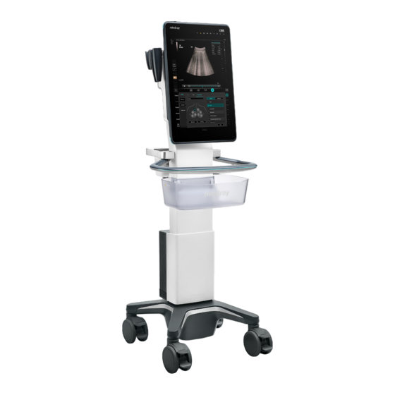
2 System Overview To order CIVCO brackets or probe sheaths, contact: Multi-Modality Imaging and Corporate Office: Toll-free within the U.S. & Canada: 800.445.6741, Toll-free Fax: 877.329.2482 Direct Dial: 319.248.6757 (International) Fax: 319.248.6660 E-mail: order@civco.com Internet: www.civco.com Introduction of Each Unit Figure 2-1 Overview of main unit Name Function... -
Page 33: I/O Module
2 System Overview Name Function Power output Provided a power interface for the peripheral devices. NOTE: The auxiliary power output socket of the peripheral equipment provided by the main unit connects the power supply of the optional peripheral equipment. Do not connect any other equipment to this interface;... -
Page 34: Indicators
2 System Overview Name Description USB port (Type-C) Used for connecting storage device such as USB disk, bar code reader, printer, footswitch, DVD recorder, etc. Serial connector Connects to the serial port for connecting to ECG of the system. USB port (Type-A) Used for connecting storage device such as USB disk, bar code reader, printer, footswitch, DVD recorder, etc. - Page 35 2 System Overview Name Description Battery capacity indicator When the battery is in charge, the battery symbol border is in green and the battery capacity indicators are as follows: • 95%~100%: the L1~L5 indicators are all in white. • 80%~95%: the L1~L4 indicators are in white and the L5 indicator blinks in white.
-
Page 36: Ecg Module
2 System Overview Name Description Power reset key Press to reset the lithium battery pack. Power capacity key Press to check the remaining battery capacity of the lithium battery pack. Remaining battery capacity Press to check the power capacity. indicators •... -
Page 37: Air Station
2 System Overview Name Description Serial connector Connects to the serial port for connecting to ECG of the system. NOTE: Ensure the system is powered off before connecting the ECG module. ECG lead port Used for ECG signal input. 2.10 Air Station Figure 2-6 Air Station Name Description... -
Page 38: Basic Operations
2 System Overview 2.11 Basic Operations 2.11.1 Screen Display Figure 2-7 Landscape orientation of the monitor 2 - 14 Operator’s Manual... - Page 39 2 System Overview Figure 2-8 Portrait orientation of the monitor Name Function Function menu tab Select to enter the corresponding function menu. Parameter Area Displays the image parameters for the active window. If there are more than one imaging modes, the parameters are displayed by each mode.
- Page 40 2 System Overview Name Function System icons area Displays the relevant system icons, such as USB memory device, network, task manager, used space of the hard disk, etc. System tool button Access the system tools. Thumbnail area Displays the thumbnail of the saved image in the current exam. Gain control Adjust the gain of the image in various modes.
-
Page 41: Select Exam Mode And Probe
2 System Overview 2.11.2 Select Exam Mode and Probe CAUTION If the exam mode is changed during a measurement, all measurement calipers on the image will be cleared. The data of general measurements will be lost, but the data of application measurements will be stored in the reports. NOTE: •... -
Page 42: Quickly Saving Image Settings
2 System Overview Name Function Imaging mode area Select imaging buttons to switch tab. Imaging parameter menu Swipe the menu downwards/upwards to see parameter controls. Setup Edit button Select to view/edit the image parameter menu under the current exam mode and probe. QSave Select [QSave], and input the name of the exam mode in the pop-up dialog box. -
Page 43: Annotations And Body Marks
2 System Overview Select [QSave] in the Menu area to bring out the Quick Save dialogue box. Select [Create] to save the current image parameters, measurements, comments, body mark settings to the exam mode. The system will ask for a new name of the exam. Restore the factory default settings Perform the following procedure: Select [QSave] in the Menu area to bring out the Quick Save dialogue box. -
Page 44: Ivocal Plus
2 System Overview Name Function Edit Comments Select to enter comment preset page, you can add custom comments button (on and change comment layout. Comment menu) Edit Markers Select to enter body mark preset page, you can change body mark button (on Body layout. - Page 45 2 System Overview Input a vocal command using the microphone, and after the command is recognized, the system automatically performs the corresponding operation. Select the icon in the Audio Control menu to pause the vocal command recognition. Setup Select the icon in the Audio Command menu to check the system recognizable commands and enter the iVocal Setup menu.
-
Page 46: Splitting Display
2 System Overview • Wakeup mode: Select to enable wakeup mode. If the wakeup mode is enabled, the iVocal Plus will automatically shut down after each command is executed. If the wakeup function is not enabled, the iVocal Plus will only shut down after the waiting time. •... -
Page 47: Izoom (Full Screen View)
2 System Overview 2.11.10iZoom (Full Screen View) This feature magnifies the image area in full screen for a better observation. 2.11.11Freeze/Unfreeze the Image Select [Freeze] to freeze a scanning image. In freeze mode, the probe stops transmitting acoustic power, and all images and parameters are frozen. TIP: After freezing an image, the system may enter cine review, measure, comment adding, body mark mode or current mode, depending on what has been preset. -
Page 48: Manual Cine Review
2 System Overview Start mark Playback mark End mark Auto Review Region Minus button Plus button For B/B+Color/B+Power mode, bottom-left corner will indicate current frame and total frames. For B/B+M/B+PW/B+CW mode, bottom-left corner will indicate time played and total time. To Exit Cine Review Select [Freeze] or [B] and the system will return to image scanning and exit cine review. -
Page 49: Linked Cine Review
2 System Overview Setting the Auto Review Region You can set a segment of cine loop which can be reviewed automatically. After the auto review region is set, the auto cine review can only be performed within this region; but the manual cine review can be performed beyond this region. -
Page 50: Frame Compare
2 System Overview There is “Display” column you can filter the images by selecting “All Items”, “Selected”, “Unselected”. Select [Clear Selected] to clear all selected images. Select [OK] to enter image comparison. Switch the multi-frame cine among the windows to review (single-frame image cannot be reviewed). -
Page 51: Frozen Image Storage
2 System Overview • When a saving is completed, a thumbnail is showed in the Thumbnail area. 2.14.2 Frozen image storage In frozen mode, Select [Pro Capture] / [Retro Capture] on the touch screen. After the cine is successfully saved, there is a thumbnail displayed on the screen. 2.15 Setting Cine Length NOTE: The system ends up saving if the cine length goes beyond the maximum value. - Page 52 2 System Overview The name, pattern and meaning of each symbol and warning label are described as follows: Symbol Description Type-BF applied part The ultrasound probes connected to this system are type-BF applied parts. The ECG leads within this system is type-BF applied part.
- Page 53 2 System Overview Symbol Description Battery power input Power consumption DC output for air probe charging holder General warning sign Mind your head. Warning; Crushing of hands Equipotentiality Product serial number Manufacture date Manufacturer Temperature limit Humidity limitation Atmospheric pressure limitation Federal law restricts this device to sale by or on the order of a licensed healthcare practitioner (USA).
- Page 54 2 System Overview Symbol Description CONFORMS TO AAMI Std. ES 60601-1, IEC Std. 60601-2-37, IEC Std. 60601-2-18; CERTIFIED TO CSA Std. C22.2 NO. 60601-1, 60601-2-37, 60601-2-18 Read this information carefully before using the system. 1. Do not place the system on a sloped surface. Otherwise the system may slide, resulting in personal injury or the system malfunction.
-
Page 55: System Preparation
System Preparation Move/Position the System Read and understand the safety precautions before positioning the system to ensure the safety of both the operator and the devices. Switch off the power, and pull out the power plug. Disconnect all cables from off-board peripheral devices. Place the system in a desired location. - Page 56 3 System Preparation WARNING • The battery is inside the machine. Only Mindray technical professionals or engineers authorized by Mindray following training can perform battery installation and uninstallation. • If you need to change the battery or buy a new one, contact your sales representative.
- Page 57 3 System Preparation • After the device enters the charging status, lock the casters to prevent the device from sliding or bumping, which may cause charging failure. • During charging, there will be a faint sound of fan, which is normal. Please do not worry. •...
-
Page 58: Power On/Off
If the system begins to function improperly, immediately stop scanning. If the system continues to function improperly, fully shut down the system and contact the Mindray Customer Service Department or a sales representative. If you use the system in a persistent improperly functioning state, you may harm the patient or damage the equipment. -
Page 59: Check The System After It Is Powered On
If you use a probe giving off excessive heat, it may burn the patient. • If you find anything not functioning properly, this may indicate that the system is defective. In this case, shut down the system immediately and contact Mindray Customer Service Department or sales representative. Operator’s Manual 3 - 5... -
Page 60: Power The System Off
3 System Preparation NOTE: When you start the system or switch between transducers, you will hear clicking sounds – this is expected behavior. 3.3.4 Power the System Off You must follow the correct procedures to power the system off. Also, after you upgrade the software or when the system is down, you need to power off and restart it. -
Page 61: Monitor Brightness/Contrast Adjustment
3 System Preparation To exit standby • Touch the screen lightly. • Press the power button. Monitor Brightness/Contrast Adjustment Perform the following procedure: in the top-right corner of the screen to open the system tool bar. Drag the slider to change the brightness/contrast on the brightness control or contrast control NOTE:... -
Page 62: Connecting/Disconnecting A Probe
When connecting or disconnecting a probe, place it in the proper position to prevent the probe from falling off or becoming damaged. • Only use probes provided by Mindray. Aftermarket probes may result in damage or cause a fire. 3.6.1 Connecting a Probe... -
Page 63: Disconnecting A Probe
3 System Preparation Perform the following procedure: Keep the cable end of the transducer to the bottom side of the system; insert the connector into the system port, then press in fully. Toggle the locking lever to the left position. Position the probe properly to avoid it being treaded on or becoming wrapped around other devices. -
Page 64: Connecting Usb Devices
USB memory device. NOTE: If the USB disk cannot be recognized by the system, please try disconnecting and then connecting again several times, or try another USB disk. If the problem still exists, please contact Mindray service engineer. Connecting the Footswitch The system supports USB port-type foot switches. -
Page 65: Connecting A Video Printer
3 System Preparation Power supply cable Connect to power supply. Data cable Connect to the USB port of this system. Perform the following procedure: Connect the data cable to USB port of the ultrasound device. Power on the system and the printer. Preset the default report printer and its attribute: Select in the top-right corner of the screen and enter “[Setup] >... - Page 66 3 System Preparation Perform the following procedure: Plug the printer power cord to an appropriate outlet. Power on the system and the printer. Make sure the ultrasound machine and the printer are connected to a same LAN, and turned on the W-LAN function of the printer.
-
Page 67: Setup
CD/DVD or USB memory device. CAUTION When the preset data is changed, be sure to save the preset data according to the methods described in this chapter. Mindray is not responsible for the loss of preset data. •... -
Page 68: General
4 Setup Item Description System Date To set the date for the system. System Time Move the cursor over the corresponding field and enter the time manually using the keyboard, or, move the cursor over the time segment, then increase or decrease the required value by clicking the icons on the right side. - Page 69 4 Setup Type Item Description Exam Setup Status after exam ends To set the system status when an exam ends. Auto Screenshot of Report After selected, perform measure application and save Page by Page single frame image, then end the patient exam, the system will save the report image in iStation.
-
Page 70: Image Preset
4 Setup Type Item Description Screen Saver Enable Screen Saver • To select a system dormancy type. After the screen saver function is enabled, tap [Browse] to select the figure used for the screen saver and tap [Preview] to see the effect. Only BMP format images with no more than 768*1024 pixels and 1-bit/8-bit/24-bit/32-bit depth are supported. -
Page 71: Application Preset
4 Setup Type Item Description Parameter Steer To set the steer mode in B + Color + PW imaging mode. • C&PW: select to adjust the sample volume in color mode and sample line in PW mode together. • C/PW: select to adjust the sample volume in color mode and sample line in PW mode separately. - Page 72 4 Setup Measure Parameter Controls are as follows: Item Description Cursor Type Type of cursor displayed on the measurement caliper and results window. Value options: • Number: the cursor always displays as “+” while different measurements are marked with numbers. •...
- Page 73 4 Setup ICA/CCA && RAR Set the measurement properties of ICA, CCA, Renal A and Aorta. Cardiac Value Range Display Set whether to display the EMINCA study. Physiology Parameter Set the unit of Temp, CVP, ICP, and Pressure. 4.1.5 OB Set the relevant information regarding the fetal gestational age, fetal growth formula and fetal weight.
- Page 74 4 Setup The author name Value of standard Unit of the Unit of the deviation measurement standard deviation value Row Num Row number (N) of the table Meas Value GA value Minimum value Measurement Maximum value value … … … …...
-
Page 75: Footswitch Function
4 Setup • Value of standard deviation. Select from one of the following: None, ±1SD, ±2SD, 3%~97%, 5%~95%, 10%~90%. • Unit of the measurement value: according to the table to import, select from mm, cm, g, kg, cm² or mm². •... -
Page 76: Access Control
Tap [Install] to begin installing a disabled option. • Tap [Uninstall] to begin uninstalling a previously-installed option. Please contact the Mindray Customer Service Department or a sales representative for details. 4.1.9 Access Control The system supports two types of users: administrator and operator. - Page 77 4 Setup Select the user to be deleted in the User List. Tap [Delete] to delete the selected user. Editing Privilege Turn on the access control function and log in to the system as Administrator before you edit privileges. Select a user, tap [Edit Privilege] to enter the “Edit user privilege” dialog box, and select or deselect the check box from the privilege list.
- Page 78 4 Setup Item Description Remark Enable strong Enable strong password to improve security. password • If the strong password is enabled and you log in to the system with the account that is added before the strong password is enabled, the system prompts a warning message to inform you whether your password conforms to the password policy.
-
Page 79: Scan Code Preset
4 Setup Item Description User field name Select [Use user field name] to customize the user field name. After that, the members and privileges cannot be edited. Enter the user field name in the field box of the “User field name” (the user field names are configured in the LDAP server. - Page 80 4 Setup Item Description Append Options The information of operator or diagnostician can be appended after selecting the check box. For example, after scanning a 1D barcode of an operator or diagnostician, the obtained data is A, and A will be displayed in “Operator” or “Diagnostician” item in Patient page automatically.
-
Page 81: Peripheral Preset
4 Setup Item Description Parameters • Input a barcode example, and you can change the information of Patient ID, Other ID, First Name, Last Name, Middle Name, Birth (Day), Birth (Month), Birth (Year), Age, Gender and etc. in the “Content” list. Note: Ignore item is used to add one line below the selected item to hide unimportant patient information. -
Page 82: Maintenance
The [Maintenance] function is designed for you to import or export user data, restore factory setting and export log. You may also execute self-test and option installation/trial through the maintenance menu. If you require other maintenance functions, please contact Mindray Customer Service Department or sales representative. -
Page 83: Ivision
Needles List Replace Update the list of needles that support eSpacial Navi function. NOTE: The list of needles must be release version provided by Mindray. Needles List Recover Restore the list of needles that support eSpacial Navi function to the last version. -
Page 84: Security
4 Setup Repetition You can choose whether to repeat the demonstration or exit after a demonstration is complete. Exhibition If the function is enabled, the system will play AVI/MP4 format files automatically. 4.1.14 Security Drive Encryption/Secure Data Wipe Encrypt the patient data stored in the hard disk. The system provides two encryption methods: Factory Default and User Define. -
Page 85: System Information
4 Setup Transmission Encryption After accessing the network, tap [VPN Config] to enter the “VPN Config” interface. Item Description Status No driver: tap [Setup Driver] to enter the "TAP-Windows 9.21.2 Setup" interface, and do as instructed. • Ready: the VPN is ready for use. •... -
Page 86: Measurement Preset
4 Setup Tap and hold any exam mode until it floats, then you can: – Drag the exam mode from “Library” column to “Selected” column to make the exam mode available for the probe. – Drag the exam mode from “Selected” column to “Library” column to make the exam mode unavailable for the probe. -
Page 87: Application Measurement Preset
4 Setup Descriptions of the attributes are shown in the following table. Attributes Descriptions Item Name & Result Results obtained from D trace are listed. The selected items will be displayed in the results window after measurement. • If PV is selected, other results become deselected. •... - Page 88 4 Setup • Adding/Removing Items: Add/Remove the general measurement item using the [>], [>>], [<] and [<<]. • Setting Default Items: Select an item from the [Selected Items] list, select [Default]. The defaulted item is marked with a √. To deselect the default tool, select it and click [Default] or set another item as the default. If a particular item is set as the default item, it automatically displays the submenu of the study when entering this measurement menu.
- Page 89 4 Setup Select [Next] to Step 2. Select the [App Region] and edit the formula. Descriptions of the attributes in the dialog box are shown in the following table. Attributes Descriptions Formula Displays the user-defined formula. Verify Used to verify if the formula is valid. Application Region Select the application region for the user-defined item.
- Page 90 4 Setup Function Method Parameter Number Function Description log(a) Logarithm with 10 as the base ≥1 avg(a,...) Average value abs(a) Absolute value Constant π, 3.1415926 NOTE: The letter “a” and “b” in the “Method” Column are parameters. The following physiological indicators can be added to the formula. Name Definition Unit...
-
Page 91: Report Preset
4 Setup Edit User-defined Items Perform the following procedure: Select defined items in the “Available Items”. Select the target item and select [Edit] on the right Remove User-defined Items • Remove Measurement/Calculation Select “User-defined” in the “Available Items”, and select the desired item. Select [Delete] on the right. -
Page 92: Comment Preset
4 Setup Set the module display in the report: select [Setting] to make a selection; – Tick the check box in front of the module name to display the module in the report; – Select [OK] to save the setting and exit. Change the patient information layout in the report template: –... -
Page 93: Comment Configure
4 Setup 4.4.1 Comment Configure Add a user-defined item Select button or tap a empty comment box to bring up the soft keyboard, then type the alphanumeric characters. Select button again to confirm it. Select available items Perform the following procedure: Select available items: Select a comment library in the drop-down list below “Application”. -
Page 94: Iworks Preset
4 Setup iWorks Preset You can customize the protocols and views in the iWorks preset screen. 4.5.1 Protocol Management • Select [Multi Select] and you can select multiple views to be copied in the list on the left. • Tap to select the protocol in the list. The protocol type can be checked on the lower part. Check to select applied exam modes in the “Exam Mode(s) applied to”... -
Page 95: Dicom Local Preset
4 Setup 4.6.1 DICOM Local Preset TIP: • AE Title should be the same with the SCU AE Title preset in the server (PACS/RIS/HIS), for example, if the AE Title of the server preset in the storage server is Storage, and the AE Title of the accepted SCU is preset as Machine, then in the figure above, the AE Title of Local should be Machine, and the AE Title of storage server should be Storage. -
Page 96: Dicom Service Preset
4 Setup Set DICOM Strategy TIP: • The DICOM strategy must be configured by qualified personnel with good knowledge of DICOM standards. • The qualified personnel must ensure the validity of the DICOM strategy. Perform the following procedure: Tap [Set DICOM Strategy]. Edit the DICOM strategy: –... - Page 97 4 Setup – Select an item in the service list, change the parameters in the above area, and tap [Update] to update the item in the service list. – Click to delete the selected service in the service list. – Select an item in the service list, click [Default] and you can see “Y”...
- Page 98 4 Setup Item Description Encapsulated PDF Select if to encapsulate PDF format report in DICOM standard. It becomes available if SCP supports the function. Storage mode Set the storage mode for image and cine file: • Parallel file: save the current file, and is ready for the storage of the next file.
- Page 99 4 Setup Item Description Settings The system supports RGB (color printing) and MONOCHROME2 (black and white printing). Please select the type the printer supports. Film Orientation Select between LANDSCAPE and PORTRAIT. Priority Specify printing task priority among HIGH, MED and LOW. Film Size Select film size among the selections listed in the drop-down list.
- Page 100 Item Description Transport Layer Security. Select whether to encrypt the data during network transportation. Strategy Name Select the preset DICOM strategy. Remove Attributes (0) Preset what DICOM elements that will not be used in worklist query. MPPS Preset MPPS setting items are described as follows: Item Description Device Name...
-
Page 101: Egateway Preset
4 Setup Query/Retrieve DICOM query/retrieve setting items are described as follows: Item Description Device Name Select the name of a device that can be added (including the local). Service Name Default is server-queryRetrieve, and it can be modified. AE Title Application Entity title.Here, it should be consistent with that of the storage commitment server. - Page 102 4 Setup eGateway Query Item Description Service Name The name of the eGateway service. IP Address Input the ADT Source IP address in the eGateway Server configuration interface. Port Input the MAQ Server Port in the eGateway Server configuration interface. Clear Click to cancel the parameter setting.
-
Page 103: Network Preset
4 Setup Type Item Description Clear Click to cancel the parameter setting. Click to add the Network service to the service list. Update Select an item in the service list, change the parameters in the above area, and click [Update] to update the item in the service list. -
Page 104: Wireless Network Connection
4 Setup MedTouch Preset You can set environment for MedTouch here and then use the MedTouch function by mobile phone or tablet computers. See MedTouch manual for details. 4.6.5 Wireless Network Connection Wireless App Select Select to enable WPS, X-Link, WLAN, Hotspot. When enable WPS in Wireless App Select, wireless probe (i3P/i3PA) can be set. -
Page 105: Q-Path Preset
4 Setup Type Item Description U-VIEW Server Device Tap to input the ID of device. Setup IP Address Tap to input IP address of U-VIEW server. Port Tap to input port of U-VIEW server. Connect Select to connect the server. 4.6.8 Q-Path Preset Q-path is a network server provided by Telexy Healthcare Inc. - Page 106 4 Setup – Default User: after the default user enters the user name and password in the field box of the “User Name” and “Password”, and tap [Save], no login is required to access the Q- Path server later. Select an appropriate item from the drop-down list of “Available Items”. Select an exam mode in the left “Exam Mode”...
-
Page 107: Exam Preparation
Exam Preparation You can start a patient exam in the following situations: • New patient information: to start a new patient exam, patient information must first be entered. • New exam: to start a new exam for patient who is already registered, the recorded information can be obtained through either iStation or Worklist. -
Page 108: Retrieve Patient Information
The system supports logging data as patient ID by using the barcode reader. CAUTION Ensure the information acquired by barcode reader is consistent with the actual information. Contact Mindray Customer Service Department to obtain the model information of the barcode scanner supported by this product. 5.1.2 Retrieve Patient Information You can import patient information from iStation or DICOM Worklist for anonymous patients. -
Page 109: Activate& Continue An Exam
5 Exam Preparation Activate& Continue an Exam 5.2.1 Activate an Exam In iStation screen, select the exam record finished within 24 hours, and click [Activate Exam] from the menu popped up; or, click [Active Exam] in iStation or Review screen to activate the exam. NOTE: •... - Page 110 This page intentionally left blank.
-
Page 111: Image Acquisition
Image Acquisition WARNING • The images displayed in this system are only reference for diagnosis. Mindray is not responsible for the correctness of diagnostic results. • Tissue Harmonic Imaging does not use contrast agents. TIP: Operations for switching between different image modes and optimizing images, see “2 System Overview”. - Page 112 6 Image Acquisition The adjustment function is disabled for wireless probe. Steer To steer the beam the probe transmits. FOV Size You can get a much larger field of view when selecting a larger FOV, but the frame rate will decrease.
- Page 113 6 Image Acquisition Dynamic Range Adjusts contrast resolution of an image, compresses or expands gray display range. The real-time dynamic range value is displayed on the image parameter area. The more the dynamic range, the more specified the information, and the lower the contrast with more noise.
- Page 114 6 Image Acquisition Dual Live Display different image effects of one probe for a better observation. Two pages of adjustable parameters are displayed on the touch screen as well; where, shared parameters and left window parameters are displayed in the B (L) page, while right window parameters are displayed in the B(R) page.
-
Page 115: Color Mode
6 Image Acquisition Only linear probes support this function. Dehaze This function can restrain noise, so as to enhance the contrast resolution of the image. Tap the [Dehaze] item on the touch screen to adjust the value. Adjust the gain along the scan line to improve the lateral resolution of the image. Tap [LGC] to enter the adjusting dialogue box. -
Page 116: Color Mode Image Parameters
6 Image Acquisition – Tap the corner of the ROI and drag to change the size. – Tap inside the ROI box and drag to change the position. Tap [Image] to open the image menu. Adjust the parameters to optimize the image. 6.2.2 Color Mode Image Parameters Color Gain Refers to the overall sensitivity to flow signals. - Page 117 6 Image Acquisition The higher the sensitivity is, the more sensitive indication for low-velocity flow becomes. Flow State Refers to optimizing the various flow states. Persistence This function is to adjust the temporal smooth to optimize the image. Smooth This feature is used to reject the noise and smooth the image. Scale This function is used to adjust the speed range of color flow, which is adjusted through PRF in the system.
-
Page 118: Power Mode
6 Image Acquisition V 1:1 This function is to display images in vertical format in the dual-split mode. After the feature is enabled, one image appears above, and the other image appears below. In the dual-split mode, tap [V 1:1] to enable this function. B Display To turn on or off the B image display as Color imaging remains active. - Page 119 6 Image Acquisition To provide a much clearer color flow image. Use low PRF to observe low-velocity flows, and use high PRF to observe high-velocity flows. ROI Adjustment To adjust the width and position of ROI in Color mode. When the ROI box is solid line, tap to change its position. When the ROI box is dotted line, tap and drag to change the size.
-
Page 120: M Mode
6 Image Acquisition Packet Size This function is an indication of the ability to detect flow, which is used to adjust the accuracy of color flow. The higher the sensitivity is, the more sensitive indication for low-velocity flow becomes. Dynamic Range This function is to adjust the transformation of echo intensity into color signal. -
Page 121: M Mode Image Parameters
6 Image Acquisition 6.4.2 M Mode Image Parameters Gain To adjust the gain of M mode image, the real-time gain value is displayed in the image parameter area. Increasing the gain will brighten the image and you can see more received signals. However, noise may also be increased. -
Page 122: Cm Image Parameters
6 Image Acquisition 6.5.2 CM Image Parameters In CM mode, parameters that can be adjusted are in accordance with those in B, M and Color modes; please refer to relevant sections of B, Color and M mode for details. The ROI size and position determine the size and position of the color flow displayed in the color M mode image. -
Page 123: Pw/Cw Mode Image Scanning
6 Image Acquisition 6.7.1 PW/CW Mode Image Scanning Perform the following procedure: Select a high-quality image during B mode or B + Color (Power) mode scanning, and adjust to position the area of interest in the center of the image. Tap [PW]/[CW] to enter PW sampling line adjustment status. - Page 124 6 Image Acquisition In the freeze and cine status, the results displayed are calculated from the current selected area. • Auto Calculation Parameter: To set the calculation results to display. • Auto Calculation Cycle: To set the heart cycle number for auto-calculation. •...
-
Page 125: Tdi
6 Image Acquisition Audio Adjusts the output audio in spectrum Doppler. PW Steering This function is used to adjust the angles for the sampling line. The PW Steer function is available only for linear probes. Invert To set the display mode of the color flow. The color scale will be inverted when the function is turned on. -
Page 126: Tdi Quantitative Analysis
6 Image Acquisition Tissue State This function is used for fast image optimization. 6.8.3 TDI Quantitative Analysis CAUTION TDI is provided for reference, not for confirming a diagnosis. NOTE: To perform the strain and strain curve, the ECG curve is in need in case of the deviation in curve. TIP: •... - Page 127 6 Image Acquisition Figure 6-1 Quantitative analysis display (taking velocity-time curve as the example) TDI review Sampling area: indicates the sampling position of the curve. The sampling lines are marked with color numbers. It can mark 8 ROIs at most. 2D grey image review •...
- Page 128 6 Image Acquisition • Only after the user chooses the image review, the quantitative analysis is available. If the user chooses the static image (only one frame), the quantitative analysis is not available. Tap [TDI QA] to enable the function. Mark the interested myocardium area.
-
Page 129: Iscape View (Real-Time Panoramic Imaging)
6 Image Acquisition Select [Exit] to exit the quantitative analysis. iScape View (Real-time Panoramic Imaging) The iScape panoramic imaging feature extends your field of view by piecing together multiple B images into a single, extended B image. Use this feature, for example, to view a complete hand or thyroid. -
Page 130: Image Review
6 Image Acquisition Optimize the B mode image: In the capture preparation status, select the B mode page tab to select B mode image optimization. Do measurement or add comment/bodymark to the image if needed. Switch to [iScape] page to enter the iScape acquisition preparation status. Select [Start Capture] or [Update] button to begin the capture. -
Page 131: Evaluate Image Quality
6 Image Acquisition 6.9.3 Evaluate image quality Many variables may affect the overall image quality. It is important to evaluate the image content and quality before an image is used for diagnosis or measurements. NOTE: • iScape panoramic imaging is intended for use by well-trained ultrasound operators or physicians. -
Page 132: Basic Procedures For Smart B-Line
6 Image Acquisition • It supports single-frame and multi-frame image file detection in B mode. 6.10.1 Basic Procedures for Smart B-line Perform the following procedure: Select an appropriate probe and exam mode. The system enters the B mode by default. Adjust the image parameters to obtain optimized images. -
Page 133: Overview
6 Image Acquisition the lung consolidation and pleural effusion occur at the same time, it is marked as C/P in the brackets and the score is 3. – Dist n (B Line distance): indicates the distance between the 2 neighboring lines and is measured in the pleura line area, among which, n corresponds to the number between the 2 B lines. -
Page 134: Smart Ivc
6 Image Acquisition After adjustment, the LVOT spectrum tracing and calculation results display in real time. Tap [Freeze] button to freeze the image, and check the Smart VTI calculation results. If necessary, you can edit the LOVT spectrum manually: Select [Edit VTI] to activate the cursor. Move the cursor to the spectrum tracing line. -
Page 135: Rimt (Real-Time Intima-Media Thickness)
6 Image Acquisition Volume responsiveness B Mode Image IVC CI Corresponds to the selected breath type: (Collapsibility Index), DI • Spontaneous Breath: displays the CI curve. (Distensibility Index), IVCV • Mechanical Ventilation: displays the DI and IVCV curve. trend curve IVC Sampling Line IVC Trending Line The horizontal axis represents the time, which is displayed in... -
Page 136: Contrast Imaging
6 Image Acquisition • RIMT inside ROI is highlighted in red, yellow and green. There is no gap between the filling area and the vascular wall. The green color indicates the normal acceptable value. The red color or yellow color indicates the abnormal unacceptable value. NOTE: RIMT should not be used on diseased vessels. -
Page 137: Basic Procedures For Contrast Imaging
6 Image Acquisition harmonic frequency much more efficient than the surrounding tissue. Blood containing the contrast agent stands out brightly against a dark background of normal tissue. CAUTION • Set MI index by instructions in the contrast agent accompanied manual. •... -
Page 138: Image Parameters
6 Image Acquisition Set [Dual Live] to be “On” to activate the dual live function. Observe the tissue image to find the target view. Inject the contrast agent, and set [Timer 1] at “ON” to start the contrast timing. When the timer begins to work, the time will be displayed on the screen. -
Page 139: Image Saving
6 Image Acquisition Select [Destruct] to enable the micro-bubble destruction function. • DestructAP: Adjust the destruct acoustic power. • Destruct Time: Adjust the destruct time. Dual Live In live mode or freeze mode, set [Dual Live] as “ON” to enable dual live function. Both the contrast mode and tissue mode are displayed. -
Page 140: Contrast Imaging Qa
TIP: • MFE imaging is available only for real-time imaging or cine file of auto review mode. If a MFE cine is reviewed manually, MFE effect cannot be displayed. • In MFE status, patient should lie down and hold breath, and transducer should be kept still. Perform the following procedure: During real-time scanning, select [MFE] to start MFE imaging. - Page 141 6 Image Acquisition Figure 6-2 Contrast QA Screen Contrast cineloop Sample area: indicates sampling position of the analysis curve. The window sample area is color-coded, 8 (maximum) sample areas can be indicated. B cineloop window Sample areas are linked in the contrast cineloop window and B cineloop window.
- Page 142 6 Image Acquisition Use [ROI Type] to select the method for determining the shapes of the sample area: Trace ROI and Ellipse ROI. The cursor is evolved in the image review area. Move the cursor to position the caliper on the reference image at the start point. Tap the arrows around the hand icon to fine-tune the cursor position if needed.
-
Page 143: Auto Ga
6 Image Acquisition – Select [Table Display] to check parameters: Item Description GOF (Goodness of Fit) Calculate the fit degree of the curve; range: 0-1, where 1 means the fit curve fits the raw curve perfectly. BI (Base Intensity) Basic intensity of no contrast agent perfusion status. AT (Arrival Time) Time point where contrast intensity appears, generally, the actual time value is 110% higher than the base intensity. -
Page 144: Auto Dfr
6 Image Acquisition Select [Smart] > [Auto GA], the system will automatically recognize and trace the target boundary to calculate. The calculation result is displayed on the screen. If the calculation result is not satisfactory, adjust the trace to recalculate. Tap the traced contour to activate the cursor. -
Page 145: Smart Nerve
6 Image Acquisition WARNING This function is not applicable for the patient whose cardiac structure can hardly be recognized under ultrasound scanning (such as obesity), or the entire cardiac structure has severely been changed (such as congenital heart disease). NOTE: If the user adjusts parameters in cardiac exam mode, such as Gain, Dynamic Range, or perform irregular scanning, such as quickly moving the probe, applying insufficient ultrasound gel, the results may not be correct. -
Page 146: Smart Fhr Ob1
6 Image Acquisition Visually check the structure of the brachial plexus, if no abnormality occurs, tap [Smart Nerve] to enter this function. The users are allowed to select Image Enhancement or Highlight Transparency. – You can select Image Enhancement levels. –... -
Page 147: Basic Procedures For Smart Ttqa
6 Image Acquisition Apart from TDI imaging function, the system also provides smart tissue tracking QA function for myocardial movement evaluation. By smart tissue tracking QA function, the ultrasound system will scan each pixel position by frame within the cardiac cycle, and then use region matching method and auto-correlation searching method to trace each spot and calculate the movement, so as to determine myocardial motion in a more quantitative way. -
Page 148: Screen Display Of Smart Ttqa
6 Image Acquisition 6.20.2 Screen Display of Smart TTQA Displays image used to generate trace curve Displays corresponding time of AVO (aortic valve open)/AVC (aortic valve close)/MVO (mitral valve open)/ MVC (mitral valve close). Display curve: Velocity/ Each curve on the image is matched with a certain segment in the Displacement/Strain/Strain Rate. -
Page 149: Select Image And Cardiac Cycle
6 Image Acquisition Displays measurement and • EDV: Maximum value of the end diastolic volume during the calculation results trace. • EDA: Maximum value of the end diastolic area (Left Ventricular) during the trace. • ESV: Maximum value of the end systolic volume (Left Ventricular) during the trace. -
Page 150: Basic Operations Of Smart Ttqa
6 Image Acquisition • Manual trace method Move the cursor along the boundary to add the trace points gradually, after trace is finished, tap the cursor twice to finish tracing. NOTE: At least 6 points should be determined by you before the system generates automated trace. Tap the cursor to make the traces on the image clockwise or anticlockwise. - Page 151 6 Image Acquisition • [ALAX]: apical long-axis view, also called 3-chamber view. • [PSAX B]: short axis view of base section, short axis view of mitral valve. • [PSAX M]: short axis view of base section, short axis view of papillary muscle. •...
-
Page 152: Bulleye
6 Image Acquisition – Circumferential Rotation Rate curve: The X-axis represents time (s); the Y-axis represents rotation by time (Deg/s). Torsion & Torsion Rate Curve The system provides left ventricular torsion data based on short axis sections of PSAX AP and PSAX B. -
Page 153: Iworks (Auto Workflow Protocol)
6 Image Acquisition 6.22 iWorks (Auto Workflow Protocol) 6.22.1 Overview The main objective of ultrasound workflow automation (iWorks) is to speed up exam times and reduce the excessive number of user interface manual key strokes that can lead to repetitive strain injuries over time. -
Page 154: Manual Examination
6 Image Acquisition View Operation In the current active view, you can perform image scanning, measurements, and adding comments and body marks, etc. Operations are the same as those for manual operation. See the relevant chapters for details. If the selected view is configured with measurement items, you can tap [Freeze] and then tap [Update] to start measurement. -
Page 155: Strain Elastography
Strain Elastography CAUTION It is provided for reference, not for confirming a diagnosis. It is produced based on the slight manual-pressure or human respiration in 2D real-time mode. The tissue hardness of the mass can be determined by the image color and brightness. Besides, the relative tissue hardness is displayed in quantitative manners. -
Page 156: Mass Measurement
7 Strain Elastography Tap [H 1:1], [V 1:1], [Full] on the touch screen to adjust. The system provides 3 types of display format: • H 1:1: Right and left display (the real-time ultrasound image appears on the left, and the elasto image appears on the right);... -
Page 157: Smart 3D
Smart 3D The operator moves the probe to change its position/angle when performing the scanning. After the scanning, the system carries out image reconstruction, and then displays a single frame of 3D image. NOTE: Smart 3D imaging is largely environment-dependent, so the images obtained are provided for reference only, not for confirming a diagnosis. -
Page 158: Roi And Voi
8 Smart 3D 8.1.2 ROI and VOI After the system enters 3D imaging, a B image with ROI displays on the screen. A line (shown in the following figure) that shows the upper edge position of VOI is inside ROI. ROI size adjustment ROI position adjustment Cut plane... -
Page 159: Mpr
8 Smart 3D TIP: You may have to adjust the threshold to obtain a clear body boundary. Set Max as 3D image rendering mode, displays the maximum echo intensity in the observation direction. This is helpful for viewing bony structures. Set Min as 3D image rendering mode. -
Page 160: Note Before Use
8 Smart 3D • Section A: corresponds to the 2D image in B mode.Section A is the sagittal section in fetal face up posture, as shown in the figure A above. • Section B: it is the horizontal section in fetal face up posture, as shown in the figure B above. •... - Page 161 8 Smart 3D • Amniotic fluid (AF) isolation – The region desired is isolated by amniotic fluid adequately. – The region for imaging is not covered by limbs or umbilical cord. • The fetus keeps still. If there is a fetal movement, you need a rescan when the fetus is still. Angle of a B tangent plane The optimum tangent plane to the fetal face 3D imaging is the sagittal section of the face.
-
Page 162: Smart 3D Image Acquisition
8 Smart 3D Scanning plane and probe movement Move the probe across the body surface. The arrow in the figure below indicates the movement of the probe. You can move the probe in the opposite direction to the arrow. Smart 3D Image Acquisition NOTE: In Smart 3D image scanning, if the probe orientation mark is oriented to the operator’s finger, perform the scan from right to left in linear scan, or rotate the probe from left to right in rocked... -
Page 163: Smart 3D Image Viewing
8 Smart 3D Smart 3D Image Viewing Activate MPR Tap [A], [B], [C] or [VR] to activate MPR or 3D image (VR). MPR Viewing In actual display, different colors of the window box and the section line are used to identify the section A, B and C. - Page 164 8 Smart 3D The system supports the observation of 3D image from 6 directions. a. Up/Down b. Down/Up c. Left/Right d. Right/Left e. Front/Back f. Back/Front Tap [Up/Down], [Left/Right] or [Front/Back] to select the direction of the figure a, c and e. Tap [Flip] on the first page to observe by the converse direction of the current direction, which is equivalent of the 180°...
- Page 165 8 Smart 3D Swipe on the current active MPR to view the image. The other two MPRs change correspondingly. The adjustment of Rendering Parameters In image viewing status, you can render the image by adjusting the relevant parameters. Tap [VR] or [MPR] to select the VR parameters or MPR parameters. •...
-
Page 166: Image Saving
8 Smart 3D Item Description To reset the parameters, rendering rotation, VOI and image effect. Reset Curve To reset the curve to be the original beeline. Render Mode Set 3D image rendering mode. The rendering manners can be applied to inversion mode. Inversion This function is to inverse the echo of the 3D image, so as to enhance observation for low-echo region, applicable for vessel, cyst and etc. - Page 167 8 Smart 3D Image review Open an image file to enter the image review mode. In this mode, you can perform the same operations as what you can in review mode. Operator’s Manual 8 - 11...
- Page 168 This page intentionally left blank.
-
Page 169: Physiological Unit Signal
Physiological Unit Signal The physiological unit signal waveform is used for checking ultrasound image in ultrasound exam (cardiac exam mainly). WARNING • Do not use the physiological traces for diagnosis and monitoring. • To avoid electric shock, the following checks shall be performed prior to an operation: –... - Page 170 9 Physiological Unit Signal Place the ECG electrodes on the patient’s body (as shown in the following figure). Right Left Right Left Yellow Black White Black Green Green (a)IEC标准 (b)AHA标准 IEC standard AHA standard Tap [Physio] to enter physio operation interface. Switch the imaging modes and display formats, adjusting the parameters to get an optimized image.
-
Page 171: Respiratory Wave
9 Physiological Unit Signal Single Trigger: When an R waveform is detected, an image will be triggered after delay time T1. The time of T1 can be edited in single mode. The image triggering operation is described as follows (Take single trigger as an example): Select exam mode. - Page 172 9 Physiological Unit Signal Parameter Description Gain Set the amplitude of the trace. Position Set the vertical position of the both traces on the image display. Speed Change the speed of the physio trace. Trig Mode Turn on/off the triggering function. Set the delay time T1 in Single trigger or Dual trigger.
-
Page 173: Measurement, Annotations And Body Mark
Measurement, Annotations and Body Mark 10.1 Measurement There are general measurements and application measurement. You can perform measurements on a zoomed image, cine reviewing image, real-time image, or frozen image. For measurement details, please refer to the Advanced Volume. WARNING •... - Page 174 10 Measurement, Annotations and Body Mark Table 10-1 Error of 2D Images Parameter Range Error Area Full Screen Within ±10% Circ Full Screen Within ±10% Angle Full Screen Within ±3% Volume Full Screen Within ±12% Table 10-2 Time/Motion Measurements Parameter Range Error Distance...
-
Page 175: Annotations
10 Measurement, Annotations and Body Mark Table 10-3 Auto Measurements Measurement Item Error Within ±10% Auto GA Within ±10% Smart TTQA Within ±20% NOTE: Within the selected field range, the measurement accuracy is ensured within the range mentioned above. The accuracy specifications are performance in the worst conditions, or based on the real test for the system, regardless of acoustic speed error. -
Page 176: Moving Annotations
10 Measurement, Annotations and Body Mark To position the arrow on the area of interest and change the orientation: tap and rotate the arrow icon to change the arrow position; tap and rotate the dotted line under arrow icon to change the arrow orientation. -
Page 177: Body Mark
10 Measurement, Annotations and Body Mark – Select button or tap a empty comment box to bring up the soft keyboard, then type the alphanumeric characters. Select button again to confirm it. – Select to delete a comment. Select [Clear All] to delete all comments. –... -
Page 178: Setting Body Mark
10 Measurement, Annotations and Body Mark Deleting all body marks Select [Clear Markers] button in the Menu area or [Clear All] in Image area to delete all the body marks. 10.3.4 Setting Body Mark Perform the following procedure: Select [Edit Markers] button in the Menu area and open Edit Body Makers dialog box. –... -
Page 179: Patient Data Management
The system patient database space is limited, please back up or clear patient data in time. • Mindray is not responsible for lost data if you DO NOT follow suggested backup procedures. 11.1 Image File Management You can store the image files either in the patient database in the system, or to external memory devices.For a save image, you can perform operations like image reviewing, analyzing and... -
Page 180: Image Storage Setting
11 Patient Data Management Single-frame file format, used to save the current screen, non-compressed format; • JPG: Single frame export format. • TIFF: Single frame export format • Multi-medium files (AVI) Multi-frame export format. • DICOM files (DCM) DICOM standard files format, single-frame or multi-frame format, used to record patient information and images;... -
Page 181: Sending Image Files
11 Patient Data Management • During image scan, saved image thumbnails will display on the right of the screen. Move the cursor onto a thumbnail, and tap twice to open the image; if the stored image is a cine file, double-click the thumbnail to enter the auto cine review. -
Page 182: Importing, Exporting And Sending A Report
11 Patient Data Management 11.2.2 Importing, exporting and sending a report Import/export report via Backup In iStation screen, select patient data, tap [Options] > [Back up]/[Restore] in the popped up menu to import or export patient information, images and reports from or to an external memory device. Perform the following procedure: Select the destination. -
Page 183: Patient Data View & Management
11 Patient Data Management When you select a patient in the patient list, the images of this patient will be displayed at the bottom of the screen. 11.3.2 Patient Data View & Management Tap to select the desired patient exam in the list, you can: Item Description Delete Exam... -
Page 184: Istorage
TIP: To use iStorage function, you need UltraAssist software in 2.0 version (with V1.0 network protocol); consult Mindray service engineer for details. Network storage is used to save image files and measurement reports to the remote PC server. For network storage setting, see the Setup chapter. -
Page 185: Report Printing
11 Patient Data Management Print current screen image In the main screen, use [Freeze] to freeze the image and tap [Print] to print the current screen image. Image print via send to function Perform the following procedure: Select the desired image in the iStation or Review screen. Tap [Send To] and select the printer in the dialog box which appears. -
Page 186: V-Access
11 Patient Data Management Print Task Displays image or report printing tasks. In the Task Management dialog box, the patient ID, name, destination, progress, type, contents and task created time are displayed. You can perform the following operations: • Click [Delete] to delete the task. •... -
Page 187: X-Link
For X-Link settings, see “4.6.7 X-Link”. • This function must be used with the monitor or ventilator of the specified model and version. Consult Mindray service engineer for details. Perform the following procedure: Tap [X-Link] and select a Bed No. in Bed Selection window. - Page 188 This page intentionally left blank.
-
Page 189: Dicom/Hl7
DICOM/HL7 NOTE: Before using DICOM, please read the electronic file DICOM CONFORMANCE STATEMENT along with the device. TIP: The DICOM package is optional, so the description here is only applicable for the system configured with the DICOM package. This system supports the following DICOM functions: •... -
Page 190: To Send Images To Storage After An Exam Ends
12 DICOM/HL7 12.1.2 To send images to storage after an exam ends TIP: To preset Sending/printing after End Exam and set a default storage server, for details see the Setup chapter. Start the ultrasound exam scan. Tap [End] to send the image or the cine to DICOM storage automatically. -
Page 191: Mpps
12 DICOM/HL7 Select the desired patient record in the displayed patient list. Select the desired patient and click [Start Exam]. The patient information is imported into the system and then an exam is started. Select [Transfer] and the patient information is imported into the [Patient Info] screen. After editing the patient information in the Patient Info screen, select [OK] to start a new exam. -
Page 192: Query/Retrieve
12 DICOM/HL7 Start the scan and obtain the image. Tap [End] each time; the system will send the image to the default DICOM storage server for storage and send storage commitment to the storage commitment server. Storage commitment is confined to the whole exam. Not each image sending can be indicated. 12.6 Query/Retrieve The query/retrieve function is used to query and retrieve patient exam records in a designated server. -
Page 193: Media Review
12 DICOM/HL7 TIP: There must be no DICOMDIR/DCMIMG/IHE_PDI files on the external storage media of the same name as the one being backed up. Otherwise, the backup cannot proceed. Ensure there is enough storage space, or the backup may fail due to shortage of space. 12.7.2 Media review Perform the following procedure: Connect the external media with DCM files to the system. -
Page 194: Back Up Structured Report
12 DICOM/HL7 Select “DICOM” in the Target box on the left side, then select the DICOM storage server in the Storage Server box on the right side. Tap [Send]. Check for the result in the DICOM Task Management dialog box. The structured report can be sent automatically. -
Page 195: Probes And Biopsy
Probes and Biopsy 13.1 Probes Probe model Probe Type Probe Figure 7LT4s Linear L14-6s Linear C4-1s Convex C5-1s Convex P10-4s Phased P7-3Ts Phased L14-6Ns Linear C11-3s Convex Operator’s Manual 13 - 1... - Page 196 13 Probes and Biopsy Probe model Probe Type Probe Figure SP5-1s Phased L16-4Hs Linear C6-2Gs Convex L20-5s Linear P8-3Ts Phased P4-2s Phased SC6-1s Convex V11-3Hs Convex L9-3s Linear P8-2s Phased P8-2Ts Phased 13 - 2 Operator’s Manual...
- Page 197 13 Probes and Biopsy Probe model Probe Type Probe Figure LAP13-4Cs Convex L14-5sp Linear L11-3VNs Linear L12-3RCs Linear L12-3VNs Linear C9-3Ts Convex Phased i3PA Phased L14-3Ws Linear Operator’s Manual 13 - 3...
-
Page 198: Laparoscopic Probe
13 Probes and Biopsy TIP: For details of TEE probe, see the relevant Operator’s Manual. 13.1.1 Laparoscopic Probe CAUTION • Under normal conditions at full acoustic power the temperature of the tip does not exceed 41°C. Do not use the laparoscopic transducer for a long time. - Page 199 13 Probes and Biopsy Name Function Hard shaft Flexible shaft Used to control the deflection of distal tip. Distal tip with transducer Converts the electrical signal to an ultrasonic signal, focusing the sound beams in a given direction while it receives the reflected ultrasonic signal and converts it to an electrical signal for transmission over the cable.
-
Page 200: Probe Functions By Part
13 Probes and Biopsy Left Zero position Right Right Left Zero position Down Down When the two deflection levers are in a vertical position with the handle, the distal tip will return to the zero position. 13.1.2 Probe Functions by Part The basic structures and corresponding functions of probes are basically the same;... -
Page 201: Orientation Of The Ultrasound Image And The Probe Head
13 Probes and Biopsy Item Description Probe head Converts the electrical signal into an ultrasonic signal, focusing the sound beams in a given direction; meanwhile, it receives the reflected ultrasonic signal and converts it into an electrical signal for transmission over the cable. The lens on the surface is the acoustic lens. -
Page 202: Procedures For Operating
13 Probes and Biopsy Orientation mark Mark 13.1.4 Procedures for Operating WARNING Disinfect the probe and sterilize the needle-guided bracket before and after an ultrasound-guided biopsy procedure is performed. Failure to do so may cause the probe and the needle-guided bracket becomes a source of infection. The proper clinical technique to be This section describes general procedures for operating the probe. - Page 203 13 Probes and Biopsy Procedures for operating (with biopsy function) Inspection before examination Connection to the system Examinations Biopsy procedure Disconnection to the system Thoroughly cleaning the needle- guided bracket Wiping off the ultrasound gel Sterilization of the needleguided bracket Thoroughly cleaning the probe Inspection after use Drying the probe...
-
Page 204: Wearing The Probe Sheath
13 Probes and Biopsy Procedures for operating (with no biopsy function) Inspection before examination Connection to the system Examinations Disconnection to the system Wiping off the ultrasound gel Thoroughly cleaning the probe Drying the probe Disinfecting the probe Rinsing the probe Drying the probe Inspection after use Storage... - Page 205 13 Probes and Biopsy A legally marketed probe sheath must be installed over the probe before performing intra-cavitary and intra-operative examination. Protective barriers may be required to minimize disease transmission. Probe sheaths are available for use with all clinical situations where infection is a concern.
-
Page 206: Probes Cleaning And Disinfection/Sterilization
13 Probes and Biopsy 13.1.6 Probes Cleaning and Disinfection/Sterilization Before and after completing each examination, clean and disinfect (or sterilize) the probes as required. When biopsy procedures have been performed, be sure to sterilize the needle-guided bracket. Fail to do so may result in the probe and the needle-guided bracket to becoming sources of infection. - Page 207 Check whether the probe has defects such as peeling, rifts, bumps, cracks, or liquid spill. If such defects exist, the probe has reached the end of its service life. In this case, stop using it and contact the Mindray service department. Operator’s Manual...
- Page 208 In this case, stop using it and contact the Mindray service department. Store the probe in a cool, clean and dry environment. And repeat the cleaning and disinfection process before the next use.
- Page 209 In this case, stop using it and contact the Mindray service department. Store the probe in a cool, clean and dry environment. And repeat the cleaning and disinfection process before the next use.
- Page 210 In this case, stop using it and contact the Mindray service department. Store the probe in a cool, clean and dry environment. And repeat the cleaning and sterilization process before the next use.
-
Page 211: Probe Environmental Conditions
13 Probes and Biopsy Compatible Cleaner, Disinfectants/Sterilants For the cleaner, disinfectants and sterilants information, please refer to Mindray Transducer Disinfectant Recommendation. 13.1.7 Probe Environmental Conditions Table 13-3 Probe Environmental Conditions Probe Conditions Ambient Relative humidity Atmospheric Model temperature (no condensation) - Page 212 13 Probes and Biopsy Table 13-3 Probe Environmental Conditions Probe Conditions Ambient Relative humidity Atmospheric Model temperature (no condensation) pressure L20-5s Operating 0°C ~ 35°C 15% ~ 80% 700 hPa ~ 1060 hPa Storage and -20°C ~ 60°C 15% ~ 90% 500 hPa ~ 1060 hPa transportation 7LT4s...
-
Page 213: Storage And Transportation
Excessive vibration – Heat generators • When the probe is sent to MINDRAY Customer Service Department or sales representative for repair, be sure to disinfect it and keep it in the carrying case to prevent infection. 13.2 Biopsy Guide WARNING •... - Page 214 13 Probes and Biopsy • Needle guided brackets are required to verified before each biopsy. If the verification fails, it indicates that the needle-guided brackets are out of service life. • Disposable brackets are packaged sterile and are single-use only, and the method of sterilization is irradiation.
-
Page 215: Needle-Guided Brackets Available
13 Probes and Biopsy The biopsy needle appears to reach the target object Dispersion of the in the image ultrasound beam Probe Biopsy Needle Ultrasound Target beam Target The biopsy needle may not have actually entered the target object even though it appears to have done so in the image. -
Page 216: Needle-Guided Bracket Inspection And Installation
(optional accessory) and a biopsy needle (provided by the user). Be sure to perform inspections before and after use of the needle-guided bracket. If an abnormality is found on the needle-guided bracket, immediately stop using it and contact MINDRAY Customer Service Department or sales representative. •... - Page 217 13 Probes and Biopsy NGB-007 Metal/needle detachable needle-guided bracket Support for needle-guided bracket Tab and groove for the needle-guided bracket Angle-adjusting base Angle shift sign Angle pinch nut Angle block Guiding block Guiding block specification Needle guide hole Needle-guided bracket pinch nut Perform the following procedure: Install the needle-guided bracket: Put on the sterile probe sheath.
- Page 218 13 Probes and Biopsy Adjust the needle angle to the proper shift as required: Loosen the angle pinch nut. Adjust the angle block to the desired level. Tighten the angle pinch nut. Install the guiding block Select a suitable guiding block and push it into the groove above the angle block, then clamp it tightly Screw the block's nut to secure the block.
- Page 219 13 Probes and Biopsy Remove the needle-guided bracket: Unscrew the Needle-guided bracket pinch nut, and remove the needle-guided bracket from the probe. Separate the probe and the needle-guided bracket. NGB-007 Plastic/needle detachable needle-guided bracket Support of needle-guided bracket Angle block Guiding block Groove and tab of the needle-guided bracket Specification of guiding block...
- Page 220 13 Probes and Biopsy Check manually to confirm that the needle-guided bracket is securely installed on the probe. Install the guiding block: Select a proper guiding block and push it into the groove above the angle block, and clamp it tightly. Insert a biopsy needle with the same specification as that of the guiding block into the hole of the guiding block.
- Page 221 13 Probes and Biopsy Separate the residual part of the needle-guide bracket and the probe from the needle. Remove the needle-guided bracket: Remove the support of needle-guided bracket from the probe. NGB-010 Metal-needle detachable needle-guided bracket Guiding block Guiding hole of the biopsy needle Support of needle-guided bracket Knob of fixing needle-guided bracket Grooves of the needle-guided bracket...
- Page 222 13 Probes and Biopsy Hold the probe by one hand, select the proper needle-guided bracket, and hold it with the other hand. Match the groove of the bracket with the tab of the probe. Amount the bracket onto the probe. Hold the probe by one hand, select proper needle-guided bracket, and hold it with the other hand, and align the grooves of the needle-guided bracket with the tabs of the probe, then push the needle-guided bracket forward, making the grooves of the needle-guided...
- Page 223 13 Probes and Biopsy Remove the guiding block slightly along the direction of the needle’s tail, and separate the residual part of the needle-guide bracket and the probe from the needle. Remove the support of needle-guided bracket from the probe. NGB-011 Metal-needle undetachable needle-guided bracket ...
- Page 224 13 Probes and Biopsy NGB-016 Metal-needle detachable needle-guided bracket Pinch nut of bracket Angle pinch nut Angle block Clamp Groove Angle-adjusting base Angle shift sign Guiding block specification Guiding block Needle guide hole Perform the following procedure: Install the needle-guided bracket: Put on the sterile probe sheath.
- Page 225 13 Probes and Biopsy Loosen the angle pinch nut. Adjust the angle block to the desired level. Tighten the angle pinch nut. Install the guiding block: Select a suitable guiding block and push it into the groove above the angle block Screw the block's nut to secure the block.
- Page 226 13 Probes and Biopsy NGB-018 Metal-needle detachable needle-guided bracket Pinch nut of bracket Angle pinch nut Angle block Clamp Groove Angle-adjusting base Angle shift sign Guiding block specification Guiding block Needle guide hole Perform the following procedure: Install the needle-guided bracket: Put on the sterile probe sheath.
- Page 227 13 Probes and Biopsy Install the guiding block: Select a suitable guiding block and push it into the groove above the angle block Screw the block's nut to secure the block. Insert a biopsy needle with the same specification as that of the guiding block into the guiding block hole.
- Page 228 13 Probes and Biopsy V-shaped cover Angle adjusting base Angle shift sign Angle pinch nut Angle block Pinch nut Perform the following procedure: Install the needle-guided bracket: Put on the sterile probe sheath. Hold the probe by one hand, select the proper needle-guided bracket, and hold it with the other hand.
- Page 229 13 Probes and Biopsy Pull the lock pin and open up the V-shaped cover to expose the needle. Separate the bracket and the probe from the needle. Remove the needle-guided bracket: Screw the pinch nut to release the needle-guided bracket. Separate the bracket and the probe.
- Page 230 13 Probes and Biopsy Put on the sterile probe sheath. Select the needle-guided bracket, and match the groove with the tab of the probe. Mount the bracket onto the probe. Rotate the retaining nut to fix the bracket and the probe. Adjust the needle angle to the proper shift as required: Loosen the angle pinch nut.
- Page 231 13 Probes and Biopsy Hold the probe, and release the pressure position of the needle. Adjust the needle-type adjusting nut manually (following the direction of the arrow). The needle moves smoothly at the vertical direction due to its gravity. Release the needle from the bracket: Hold the probe.
- Page 232 13 Probes and Biopsy Remove the needle-guided bracket: Rotate the clamping nuts of the needle guided-bracket on right and left side (following the direction of the arrow). The needle guided-bracket is separate from the probe. Hold the probe and take out the bracket. NGB-025 Metal-needle undetachable needle-guided bracket Pinch nut Intra-cavity probe...
- Page 233 13 Probes and Biopsy Open the clamp. Insert the front clamp to the front groove, and align front clamp with front groove. Push the biopsy forward (arrow’s direction) until the locating pole inserting into the location hole. Turn the lower clamp against the intra-cavity probe. Tighten the nut to lock the biopsy (arrow’s direction) Remove the needle-guided bracket: Hold the prober in the left hand;...
- Page 234 13 Probes and Biopsy NGB-034 Metal-needle detachable needle-guided bracket Needle fixing nut Guiding groove Angle fixing nut Angle adjusting base Needle type dial scale Needle adjusting base V-shape cover Lock pin Needle guide hole V-shaped guiding block Clamp Perform the following procedure: Install the needle-guided bracket: Put on the sterile probe sheath.
- Page 235 13 Probes and Biopsy Adjust the needle angle to the proper shift as required: Loosen the angle pinch nut. Adjust the angle block to the desired level. Tighten the angle pinch nut. Insert the biopsy needle: Adjust the dial scale to the required needle type shift. Pull the lock pin and close the V-shaped cover to fix the lock pin in the groove of the needle type adjusting base, so as to install the needle into the guiding hole.
- Page 236 13 Probes and Biopsy NGB-036 Metal-needle detachable needle-guided bracket Angle locking nut Angle adjusting block Angle marker Angle adjusting base Groove Slot Right, left retaining nut Right, left clamp Perform the following procedure: Install the needle-guided bracket: Put on the sterile probe sheath. Select the needle-guided bracket, and match the groove with the tab of the probe.
- Page 237 13 Probes and Biopsy Adjust the needle angle to the proper shift as required: Loosen the angle pinch nut. Adjust the angle block to the desired level. Tighten the angle pinch nut. Insert the biopsy needle: Hold the probe. Press the biopsy needle to separate needle guided V-shaped block from pressure position of the needle Put the needle into the needle guided-bracket, and the needle leans to V-shaped block.
- Page 238 13 Probes and Biopsy Release the needle from the bracket: Hold the probe. Press the biopsy needle to separate the needle from pressure position of the needle. Separate the bracket and the probe from the needle. Remove the needle-guided bracket: Rotate the clamping nuts of the needle guided-bracket on right and left side (following the direction of the arrow).
- Page 239 13 Probes and Biopsy Hold the probe and take out the bracket. NGB-043 Metal-needle detachable needle-guided bracket Locking nut of left and right clamps Groove Guide frame Guide block hole Clamps Perform the following procedure: Install the needle-guided bracket: Put on the sterile probe sheath. Hold the probe in one hand, select the correct needle-guided bracket and hold it with the other hand.
- Page 240 13 Probes and Biopsy Rotate the locking nut in the direction of the arrow shown on the figure to separate the bracket from the probe. Hold the probe and take out the bracket. NGB-044 Metal-needle detachable needle-guided bracket Right clamp Groove Guiding block fixing frame Locking nut of left and right clamps...
- Page 241 13 Probes and Biopsy Put on the sterile probe sheath. Hold the probe in one hand, select the correct needle-guided bracket and hold it with the other hand. Match the grooves of the needle-guided bracket to the tabs of the probe. Mount the bracket onto the probe, and rotate the locking nut to fix the bracket.
- Page 242 13 Probes and Biopsy Insert a biopsy needle with the same specification as that of the guiding block into the guiding block hole Remove the needle-guided bracket: Hold the probe and remove the needle. Loosen the guiding block nut, and remove it from the guiding block fixing frame. Rotate the clamping nuts of the needle guided-bracket.
- Page 243 13 Probes and Biopsy NGB-054 metal-needle detachable needle-guided bracket Angle adjusting block Angle locking nut Right clamp of the bracket Left clamp of the bracket Needle clamping cover Needle-shaped adjusting nut Locking nuts of the guided bracket at the right and left sides Operator’s Manual 13 - 49...
- Page 244 13 Probes and Biopsy Torsion spring of the needle pressure cover Biopsy needle pressure position Angle adjusting base Perform the following procedure: Install the needle-guided bracket: Put on the sterile transducer sheath. Hold the transducer in one hand, select the correct needle-guided bracket and hold it with the other hand.
- Page 245 13 Probes and Biopsy Hold the transducer, and release the pressure position of the needle. Adjust the needle- shaped adjusting nut manually (following the direction of the arrow). The needle moves smoothly at the vertical direction due to its gravity. Release the needle from the bracket: Hold the probe.
-
Page 246: Verifying The Biopsy Guide Line
13 Probes and Biopsy Hold the transducer. Press the biopsy needle pressure position to separate the biopsy needle from the pressure position. Separate the bracket and the transducer from the needle. Rotate the locking nuts of the needle guided-bracket at the right and left sides (following the direction of the arrow). -
Page 247: Clean And Sterilize The Needle-Guided Bracket
If such defects exist, the bracket has reached the end of its service life. In this case, stop using it and contact the Mindray service department. • It is recommended to use immersion sterilization for plastic needle-guided brackets and high-pressure steam sterilization for metal needle-guided brackets. - Page 248 13 Probes and Biopsy • For detailed operations about the cleaning solvent, sterilant and high- temperature steam sterilizer, see the respective operator’s manuals provided by the manufacturer. NOTE: Disposable components are packaged sterile and are single-use only. Do not use if integrity of packaging is violated or if expiration date has passed.
-
Page 249: Storage And Transportation
Between examinations, keep the needle-guided bracket in a sterile environment. • If the needle-guided bracket is sent to your MINDRAY representative for repair, be sure to disinfect or sterilize it and keep it in the carrying case to prevent infection. -
Page 250: Disposal
Be sure to sterilize the needle-guided bracket before disposing of it. Disposal of the needle-guided brackets is in accordance with SanPiN 2.1.7.2790-10. Contact your MINDRAY representative when disposing of this device. 13.3 Middle Line Middle Line helps to locate and observe the focus point of lithotripsy wave during lithotripsy treatment. -
Page 251: Interface
13 Probes and Biopsy CAUTION • Keep the magnetizer away from any device that is sensitive to magnetic fields. Never place or hold the magnetizer within 1 m of the probe. • The eSpacial Navi system supports only the needle types listed on the needle list. - Page 252 13 Probes and Biopsy In Plane Needle Guidance GUI Needle position in the ultrasound plane Needle tip position in the ultrasound plane Needle guidance trajectory Scale of guideline (5 mm/scale) Out of Plane Needle Guidance GUI Needle projection position in the ultrasound plane Position at which the needle cross the ultrasound plane Projection position of the needle guidance trajectory in the ultrasound plane Scale of guideline (5mm/scale)
-
Page 253: Preset
13 Probes and Biopsy 13.4.2 Preset eSpacial Navi Needle Menu Enter the Needle menu, and controls are as shown in Table 13-6. Table 13-6 eSpacial Navi Needle settings Item Description Needle Select the desired needle from the drop-down list. You can set the most frequently used needle to a favorite one. Display Favourite Only After it is ticked, only the favorite needles are displayed on the needles list. -
Page 254: Procedure
13 Probes and Biopsy Introduce a needle into the cap, and ensure that the needle tip contacts the bottom of the needle cap. If the needle cap associated with the needle does not meet the requirements, you are recommended to use BBraunSterican <35 mm needles cap or B&D Microlance <35 mm needles cap. - Page 255 13 Probes and Biopsy • No cleaning and disinfecting may result in the magnetizer becoming a source of infection. • Please follow the disinfectant manufacturer's manual for performing cleaning and disinfection, including preparing sterile water and cleaning and disinfection time. NOTE: •...
-
Page 256: Storage And Transportation
Disinfecting by Immersion Perform the following procedure: Wear sterile gloves to prevent infection. Clean the magnetizer before disinfecting it. MINDRAY recommends the compatible solutions to disinfect the magnetizer. – Refer to the instructions provided by the chemical manufacturer concerning concentration of the disinfectant solution, method of disinfection and dilution and cautions during use. -
Page 257: Dvr Recording
DVR Recording NOTE: Strictly observe the procedures described here to perform the recording and replaying operations; otherwise it may result in data loss or system malfunction. The system provides built-in DVR recording function. You can use the DVR to record and replay videos and audios that can be stored in DVD disc or hard disc. -
Page 258: Dvr Video Replaying
14 DVR Recording Select the destination and the target file, tap [Send] to send the file to the selected path. During sending progress, the icon displays as 14.3 DVR Video Replaying You can replay the video and audio record. 14.3.1 Replay on PC Connect the USB disk or optical disk with the file to the PC, and open the file directly. -
Page 259: System Maintenance
The responsibility for maintenance and management of the product after delivery resides with the customer who has purchased the product. If you have any questions, please contact Mindray Customer Service Department or sales representative. WARNING •... - Page 260 15 System Maintenance Cleaning probes Tools: mild soapy water, dry soft cloth, soft brush Method: Wipe out the dust attached to surface of probe head, connector and cable. Use soft brush to brush the dust inside probe connector gently. Remained stain or dust attached to surface of cable or surface of connector should be washed out by cloth with a little soapy water, and then air-dry.
-
Page 261: Cleaning The Peripherals
15 System Maintenance Cleaning the dust-proof cover CAUTION Please clean all the system’s dustproof covers periodically (once per month). Failure to do so may result in system damage. Cleaning times can be increased when the system is used in the open air or somewhere more dusty. Perform the following procedure: Press the clip of the dust-proof cover and unfold it outwards (shown in the figure below). -
Page 262: Disinfecting The Main Unit
15 System Maintenance 15.1.3 Disinfecting the Main Unit WARNING • Use only Mindray approved disinfectants and methods listed in this section to disinfect the main unit. Warranty does not cover damage caused by unapproved substances or methods. • Do not mix disinfectants, as hazardous gases may result. - Page 263 15 System Maintenance Table 15-1 Manufacturer Product Name Type Super Sani-Cloth Wipe Bode Chemie Gmbh Mikrobac Tissues Wipe Diversey VIREX TB Solution ® Schulke Schulke mikrozid Sensitive Wipes Wipe Dr.Schumacher GmbH CLEANISEPT WIPES Wipe Parker Laboratories Inc. PROTEX ULTRA Wipe Laboratoires ANIOS wipe anios clean up Wipe...
-
Page 264: Checking The Probe
15 System Maintenance Ventilation holes Probe sockets I/O panel Loudspeaker Trolley back handle Remove any residue with a water-moistened soft cloth on the main unit. Wipe off water on the main unit using sterile cloth or gauze. Do not dry the main unit by heating. -
Page 265: System Hard Drive Backup
15.2 Troubleshooting If any persistent system malfunction is experienced, e.g., an onscreen error message, blank imaging screen, absent menus, see the table below. If the failure cannot be resolved, contact the Mindray Customer Service Department or a sales representative. Failure... - Page 266 This page intentionally left blank.
- Page 267 Wireless LAN The system provides wireless net adapter configuration, so as to assist information query and unlimited network service. The ultrasound system can be connected to router, mobile phone, tablet, ultrasound workstation, server network device and so on via wireless network. WARNING •...
-
Page 268: A Wireless Lan
Host Name: displays the machine name of the system, if changed, the system should be restarted. Tap [OK] to save current setting or tap [Cancel] to exit. EAP Network For setting EAP network, contact Mindray Customer Service Department or the sales representatives. Specifications Table A-1 Wireless specification and technology... -
Page 269: Troubleshooting
AP. • Check for IP address conflict. If yes, set the IP address correctly. • Check if Mindray recommended wireless AP is used. If not, verify the AP effective transmission rate meets the throughput requirements of the connected devices. - Page 270 A Wireless LAN Failure Measure The ultrasonic device is • Check if Mindray recommended wireless AP is used. If not, frequently off line or verify the AP effective transmission rate meets the throughput disconnects from the requirements of the connected devices.
-
Page 271: B Iscanhelper
iScanHelper By providing the referential information, such as, the ultrasonic image, the anatomic graphic, scanning pictures/other scanning tips or diagnosis comments, the system helps the doctors to operate the scanning by iScanHelper. Furthermore, it is a good platform for the self-learning and training of ultrasound scanning technique for doctors. -
Page 272: Basic Screen And Operation
B iScanHelper Basic Screen and Operation B.3.1 Help Information Area Ultrasonic image, anatomic graphic, scanning picture and scanning tips are provided in the “iScanHelper” menu. Anatomic Ultrasonic graphic image Scanning Scanning picture tips • Ultrasonic image It is used to compare with images scanned by the operator. •... -
Page 273: C Ivision
iVision The iVision function is used to demonstrate the stored images. Image files are played one by one according to file names (including system-relevant and PC-compatible format images). Perform the following procedure: and select [Setup] > [System] > [iVision] to enter the iVision setting screen. Add the contents to be played and select demo mode. - Page 274 This page intentionally left blank.
- Page 275 After the input command is recognized, the system automatically performs the corresponding operations. Vocal command Operation Hello Mindray Turn On Audio Control Bye Mindray Turn Off Audio Control...
-
Page 276: D List Of Vocal Commands
D List of Vocal Commands Vocal command Operation Zoom Out Zoom Out Image Smart Track Turn on/Turn off Smart Track Mode Sound Volume Up Turn Sound Volume Up Sound Volume Down Turn Sound Volume Down Angle More Angle More One Angle Less Angle Less One Left Steer... - Page 277 D List of Vocal Commands Vocal command Operation Needle Visualized Switch Exam Mode to Needle Visualized Optimization Optimization Open Patient Info Open Patient Info Dialog Dialog Close Patient Info Close Patient Info Dialog Dialog Open Probe Dialog Open Probe Dialog Close Probe Dialog Close Probe Dialog Open Review Dialog...
- Page 278 This page intentionally left blank.
-
Page 279: E Electrical Safety Inspection
Electrical Safety Inspection The following electrical safety tests are recommended as part of a comprehensive preventive maintenance program. They are a proven means of detecting abnormalities that, if undetected, could prove dangerous to either the patient or the operator. Additional tests may be required according to local regulations. -
Page 280: Device Enclosure And Accessories
E Electrical Safety Inspection Device Enclosure and Accessories E.2.1 Visual Inspection Test Item Acceptance Criteria The enclosure and No physical damage to the enclosure and accessories. accessories No physical damage to meters, switches, connectors, etc. No residue of fluid spillage (e.g., water, coffee, chemicals, etc.). No loose or missing parts (e.g., knobs, dials, terminals, etc.). -
Page 281: Enclosure Leakage Test
E Electrical Safety Inspection • normal polarity with open neutral (Single Fault Condition); • reverse polarity with open neutral (Single Fault Condition). LIMITS • For ES 60601-1: 300 μA in Normal Condition. – 1000 μA in Single Fault Condition. – •... -
Page 282: Mains On Applied Part Leakage
E Electrical Safety Inspection Mains on Applied Part Leakage The Mains on Applied Part test applies a test voltage, which is 110% of the mains voltage using a limiting resistance, to selected applied part terminals. Current measurements are then taken between the selected applied part and earth. - Page 283 Portable RF communications equipment (including peripherals such as antenna cables and external antennas) should be used no closer than 30 cm (12 inches) to any part of the TEX20, including cables specified by the manufacturer. Otherwise, degradation of the performance of this equipment could result.
-
Page 284: F Emc Guidance And Manufacturer's Declaration
Date/time information. Table F-1 GUIDANCE AND MINDRAY DECLARATION-ELECTROMAGNETIC EMISSIONS The system configured with air charge module is intended for use in the electromagnetic environment specified below. The customer or the user of system should assure that it is used in such an environment. - Page 285 F EMC Guidance and Manufacturer’s Declaration Table F-1 GUIDANCE AND MINDRAY DECLARATION-ELECTROMAGNETIC EMISSIONS The system configured with air charge module is intended for use in the electromagnetic environment specified below. The customer or the user of system should assure that it is used in such an environment.
- Page 286 F EMC Guidance and Manufacturer’s Declaration Table F-2 GUIDANCE AND MINDRAY DECLARATION-ELECTROMAGNETIC EMISSIONS The Probe P7-3Ts/P8-3Ts/P8-2Ts/LAP13-4Cs which integrated in the system (not including air charge module) is intended for use in the electromagnetic environment specified below. The customer or the user of system should assure that it is used in such an environment.
- Page 287 F EMC Guidance and Manufacturer’s Declaration GUIDANCE AND MINDRAY DECLARATION-ELECTROMAGNETIC EMISSIONS The system not configured with air charge module or the probe P7-3Ts/P8-3Ts/P8-2Ts/LAP13- 4Cs is intended for use in the electromagnetic environment specified below. The customer or the user of system should assure that it is used in such an environment.
- Page 288 F EMC Guidance and Manufacturer’s Declaration Table F-3 GUIDANCE AND MINDRAY DECLARATION-ELECTROMAGNETIC IMMUNITY The system is intended for use in the electromagnetic environment specified below. The customer or the user of system should assure that it is used in such an environment.
- Page 289 F EMC Guidance and Manufacturer’s Declaration Table F-4 GUIDANCE AND MINDRAY DECLARATION-ELECTROMAGNETIC IMMUNITY The system is intended for use in the electromagnetic environment specified below. The customer or the user of system should assure that it is used in such an environment.
- Page 290 F EMC Guidance and Manufacturer’s Declaration Table F-5 RECOMMENDED SEPARATION DISTANCES BETWEEN PORTABLE AND MOBILE RF COMMUNICATION DEVICE AND THE SYSTEM The system is intended for use in an electromagnetic environment in which radiated RF disturbance are controlled. The customer or the user of system can help prevent electromagnetic interference by maintaining a minimum distance between portable and mobile RF communication equipment (transmitters) and system as recommended below, according to the maximum output power of the communication equipment.
-
Page 291: G Acoustic Output
Acoustic Output This section of the operator’s manual applies to the overall system including the main unit, probes, accessories and peripherals. This section contains important safety information for operators of the device, pertaining to acoustic output and how to control patient exposure through use of the ALARA (as low as reasonably achievable) principle. -
Page 292: Mi/Ti Explanation
G Acoustic Output Additional information regarding the concept of ALARA and the possible bioeffects of Ultrasound is “Medical available in a document from the AIUM (American Institute of Ultrasound Medicine) title Ultrasound Safety”. MI/TI Explanation G.4.1 Basic Knowledge of MI and TI Mechanical Bioeffect and Thermal Bioeffect The relationship of various ultrasound output parameters (frequency, acoustic pressure and intensity, etc.) to bioeffects is not fully understood presently. -
Page 293: Mi/Ti Display
G Acoustic Output Although the output power is automatically controlled for the selected applications, high TI values should be kept to a minimum or avoided in obstetric applications. WFUMB (World Federation for Ultrasound in Medicine and Biology) guidelines: state that temperature increase of 4 degree C for 5 min or more should be considered as potentially hazardous to embryonic and fetal tissue. -
Page 294: Acoustic Power Control
G Acoustic Output the Setup menu). In the factory default settings, the Acoustic Output is limited below 100%. Following the ALARA restriction, you are allowed to increase the acoustic power under FDA 510 (k) Guidance-Track 3 limits and to set it in the image preset screen. The acoustic output of the system has been measured and calculated in accordance with IEC60601- 2-37: 2015, FDA 510(K) GUIDANCE, IEC 62359: 2017, Ultrasonics-Field characterization-Test methods for the deter mination of thermal and mechanical indices related to medical diagnostic... -
Page 295: Limits Of Acoustic Output
G Acoustic Output Where I is the attenuated intensity, I is the intensity measured in a water tank (at distance atten water z), fc is the center frequency of the ultrasound wave (as measured in water), and z is the distance from the probe. -
Page 296: References For Acoustic Power And Safety
G Acoustic Output Acoustic Quantities Total Uncertainties (Standard) Power 26.48% for non-scan modes; 6.03% for scan modes. Frequency 0.22% Pressure 13.01% 26.48% for non-scan modes; 26.95% for scan modes. 26.5% Mechanical Index 13.01% Total Uncertainty for TIS 26.48% for non-scan modes; 6.03% for scan modes. - Page 297 Probe Dimensions Model Length (mm) Width (mm) Height (mm) Cable Length (mm) C5-1s 111.9 76.7 2050±50 P10-4s 82.5 28.5 21.2 2050±50 P7-3Ts 1500 59.6 59.1 1530±50 L14-6Ns 101.6 25.7 2050±50 C11-3s 96.4 32.8 2050±50 SP5-1s 102.6 38.2 30.4 2050±50 C6-2Gs 117.4 39.4 2790±50...
-
Page 298: H Probe Dimensions
H Probe Dimensions Length Height (Max.) Width (Max.) H - 2 Operator’s Manual... - Page 299 Indications for use Intended Use: Diagnostic ultrasound imaging or fluid flow analysis of the human body as follows: Clinical Application Mode of Operation General(Track 1 Color Amplitude Combined Specific (Track 1 & 3) B Other (Specify) Only) Doppler Doppler (specify) Ophthalmic Ophthalmic Note 1...
- Page 300 I Indications for use Transducer: C5-1s Intended Use: Diagnostic ultrasound imaging or fluid flow analysis of the human body as follows: Clinical Application Mode of Operation General(Track Specific (Track 1 & 3) PWD CWD Color Amplitude Combined Other (Specify) 1 Only) Doppler Doppler (specify)
- Page 301 I Indications for use Transducer: C4-1s Intended Use: Diagnostic ultrasound imaging or fluid flow analysis of the human body as follows: Clinical Application Mode of Operation General(Track Specific (Track 1 & 3) PWD CWD Color Amplitude Combined Other (Specify) Doppler Doppler (specify) 1 Only)
- Page 302 I Indications for use Transducer: SC6-1s Intended Use: Diagnostic ultrasound imaging or fluid flow analysis of the human body as follows: Clinical Application Mode of Operation General(Track Specific (Track 1 & 3) Color Amplitude Combined Other (Specify) 1 Only) Doppler Doppler (specify) Ophthalmic...
- Page 303 I Indications for use Transducer: C11-3s Intended Use: Diagnostic ultrasound imaging or fluid flow analysis of the human body as follows: Clinical Application Mode of Operation General(Track Specific (Track 1 & 3) Color Amplitude Combined Other (Specify) 1 Only) Doppler Doppler (specify) Ophthalmic...
- Page 304 I Indications for use Transducer: C9-3Ts Intended Use: Diagnostic ultrasound imaging or fluid flow analysis of the human body as follows: Clinical Application Mode of Operation General(Track Specific (Track 1 & 3) PWD CWD Color Amplitude Combined Other (Specify) 1 Only) Doppler Doppler (specify)
- Page 305 I Indications for use Transducer: C6-2Gs Intended Use: Diagnostic ultrasound imaging or fluid flow analysis of the human body as follows: Clinical Application Mode of Operation General(Track Specific (Track 1 & 3) Color Amplitude Combined Other (Specify) 1 Only) Doppler Doppler (specify) Ophthalmic...
- Page 306 I Indications for use Transducer: L14-6s Intended Use: Diagnostic ultrasound imaging or fluid flow analysis of the human body as follows: Clinical Application Mode of Operation General(Track Specific (Track 1 & 3) Color Amplitude Combined Other (Specify) 1 Only) Doppler Doppler (specify) Ophthalmic...
- Page 307 I Indications for use Transducer: L14-5sp Intended Use: Diagnostic ultrasound imaging or fluid flow analysis of the human body as follows: Clinical Application Mode of Operation General(Track Specific (Track 1 & 3) PWD CWD Color Amplitude Combined Other (Specify) 1 Only) Doppler Doppler (specify)
- Page 308 I Indications for use Transducer: L14-6Ns Intended Use: Diagnostic ultrasound imaging or fluid flow analysis of the human body as follows: Clinical Application Mode of Operation General(Track Specific (Track 1 & 3) PWD CWD Color Amplitude Combined Other (Specify) 1 Only) Doppler Doppler (specify)
- Page 309 I Indications for use Transducer: L9-3s Intended Use: Diagnostic ultrasound imaging or fluid flow analysis of the human body as follows: Clinical Application Mode of Operation General(Track Specific (Track 1 & 3) Color Amplitude Combined Other (Specify) 1 Only) Doppler Doppler (specify) Ophthalmic...
- Page 310 I Indications for use Transducer: L20-5s Intended Use: Diagnostic ultrasound imaging or fluid flow analysis of the human body as follows: Clinical Application Mode of Operation General(Track Specific (Track 1 & 3) PWD CWD Color Amplitude Combined Other (Specify) 1 Only) Doppler Doppler (specify)
- Page 311 I Indications for use Transducer: L16-4Hs Intended Use: Diagnostic ultrasound imaging or fluid flow analysis of the human body as follows: Clinical Application Mode of Operation General(Track Specific (Track 1 & 3) PWD CWD Color Amplitude Combined Other (Specify) 1 Only) Doppler Doppler (specify)
- Page 312 I Indications for use Transducer: 7LT4s Intended Use: Diagnostic ultrasound imaging or fluid flow analysis of the human body as follows: Clinical Application Mode of Operation General(Track Specific (Track 1 & 3) PWD CWD Color Amplitude Combined Other (Specify) 1 Only) Doppler Doppler (specify)
- Page 313 I Indications for use Transducer: L12-3RCs Intended Use: Diagnostic ultrasound imaging or fluid flow analysis of the human body as follows: Clinical Application Mode of Operation General(Track Specific (Track 1 & 3) PWD CWD Color Amplitude Combined Other (Specify) 1 Only) Doppler Doppler (specify)
- Page 314 I Indications for use Transducer: L11-3VNs Intended Use: Diagnostic ultrasound imaging or fluid flow analysis of the human body as follows: Clinical Application Mode of Operation General(Track Specific (Track 1 & 3) PWD CWD Color Amplitude Combined Other (Specify) 1 Only) Doppler Doppler (specify)
- Page 315 I Indications for use Transducer: L12-3VNs Intended Use: Diagnostic ultrasound imaging or fluid flow analysis of the human body as follows: Clinical Application Mode of Operation General(Track Specific (Track 1 & 3) PWD CWD Color Amplitude Combined Other (Specify) 1 Only) Doppler Doppler (specify)
- Page 316 I Indications for use Transducer: L14-3Ws Intended Use: Diagnostic ultrasound imaging or fluid flow analysis of the human body as follows: Clinical Application Mode of Operation General(Track Specific (Track 1 & 3) Color Amplitude Combined Other (Specify) 1 Only) Doppler Doppler (specify) Ophthalmic...
- Page 317 I Indications for use Transducer: V11-3Hs Intended Use: Diagnostic ultrasound imaging or fluid flow analysis of the human body as follows: Clinical Application Mode of Operation General(Track Specific (Track 1 & 3) Color Amplitude Combined Other (Specify) 1 Only) Doppler Doppler (specify) Ophthalmic...
- Page 318 I Indications for use Transducer: P4-2s Intended Use: Diagnostic ultrasound imaging or fluid flow analysis of the human body as follows: Clinical Application Mode of Operation General(Track Specific (Track 1 & 3) Color Amplitude Combined Other (Specify) 1 Only) Doppler Doppler (specify) Ophthalmic...
- Page 319 I Indications for use Transducer: SP5-1s Intended Use: Diagnostic ultrasound imaging or fluid flow analysis of the human body as follows: Clinical Application Mode of Operation General(Track Specific (Track 1 & 3) Color Amplitude Combined Other (Specify) 1 Only) Doppler Doppler (specify) Ophthalmic...
- Page 320 I Indications for use Transducer: P10-4s Intended Use: Diagnostic ultrasound imaging or fluid flow analysis of the human body as follows: Clinical Application Mode of Operation General(Track Specific (Track 1 & 3) Color Amplitude Combined Other (Specify) 1 Only) Doppler Doppler (specify) Ophthalmic...
- Page 321 I Indications for use Transducer: P8-2s Intended Use: Diagnostic ultrasound imaging or fluid flow analysis of the human body as follows: Clinical Application Mode of Operation General(Track Specific (Track 1 & 3) Color Amplitude Combined Other (Specify) 1 Only) Doppler Doppler (specify) Ophthalmic...
- Page 322 I Indications for use Transducer: Intended Use: Diagnostic ultrasound imaging or fluid flow analysis of the human body as follows: Clinical Application Mode of Operation General(Track Specific (Track 1 & 3) Color Amplitude Combined Other (Specify) 1 Only) Doppler Doppler (specify) Ophthalmic Ophthalmic...
- Page 323 I Indications for use Transducer: i3PA Intended Use: Diagnostic ultrasound imaging or fluid flow analysis of the human body as follows: Clinical Application Mode of Operation General(Track Specific (Track 1 & 3) Color Amplitude Combined Other (Specify) 1 Only) Doppler Doppler (specify) Ophthalmic...
- Page 324 I Indications for use Transducer: P7-3Ts Intended Use: Diagnostic ultrasound imaging or fluid flow analysis of the human body as follows: Clinical Application Mode of Operation General(Track Specific (Track 1 & 3) Color Amplitude Combined Other (Specify) 1 Only) Doppler Doppler (specify) Ophthalmic...
- Page 325 I Indications for use Transducer: P8-3Ts Intended Use: Diagnostic ultrasound imaging or fluid flow analysis of the human body as follows: Clinical Application Mode of Operation General(Track Specific (Track 1 & 3) Color Amplitude Combined Other (Specify) 1 Only) Doppler Doppler (specify) Ophthalmic...
- Page 326 I Indications for use Transducer: P8-2Ts Intended Use: Diagnostic ultrasound imaging or fluid flow analysis of the human body as follows: Clinical Application Mode of Operation General(Track Specific (Track 1 & 3) Color Amplitude Combined Other (Specify) 1 Only) Doppler Doppler (specify) Ophthalmic...
- Page 327 I Indications for use Transducer: LAP13-4Cs Intended Use: Diagnostic ultrasound imaging or fluid flow analysis of the human body as follows: Clinical Application Mode of Operation General(Track Specific (Track 1 & 3) PWD CWD Color Amplitude Combined Other (Specify) 1 Only) Doppler Doppler (specify)
- Page 328 This page intentionally left blank.
- Page 330 P/N: 046-023006-00 (2.0)
Need help?
Do you have a question about the TEX20 and is the answer not in the manual?
Questions and answers
Why my TE X does not recognize the L 1 4-3Ws probe?
The Mindray TEX20 may not recognize the L14-3Ws probe due to one of the following reasons:
1. The probe is faulty.
2. The mainboard is faulty.
To determine the cause, perform a cross-test by connecting multiple probes to the main unit:
- If only the L14-3Ws probe fails, the probe is likely faulty.
- If no probes work, the mainboard may be faulty.
Based on the result, replace the faulty probe or mainboard.
This answer is automatically generated