Table of Contents
Advertisement
Quick Links
Advertisement
Table of Contents
Troubleshooting

Related Manuals for Mindray Zonare ZS3KP Elite


Summary of Contents for Mindray Zonare ZS3KP Elite
- Page 1 ZS3KP Elite/ZS3 Elite/ZS4 Diagnostic Ultrasound System Service Manual...
- Page 2 ©2023 Shenzhen Mindray Bio-Medical Electronics Co., Ltd. All rights reserved. ZONARE, the ZONARE logo, ZS3KP Elite, ZS3 Elite, ZS4, ZS3 and z.one are all trademarks of Shenzhen Mindray Bio-Medical Electronics Co., Ltd.. All other trademarks are the property of their respective holders.
-
Page 3: Table Of Contents
TABLE OF CONTENTS Introduction ............................7 Purpose ..............................8 Definitions/Acronyms ..........................9 Documentation Conventions ....................... 10 Symbols..............................10 Safety ..............................12 Facility Needs ............................12 Notes When Returning or Transporting the System, Probes, and Repair Parts ......13 Warning & Cautions ..........................13 System Specifications ........................ - Page 4 Enabling Account Access Control ...................... 60 System Login ............................60 Local Privilege Management....................... 61 LDAP Privilege Management ......................67 User Field Name ........................... 69 Enable Barcode Login .......................... 69 Enable Encryption ..........................70 Patient Information Management ....................71 Patient Information ..........................71 New Patient Information ........................
- Page 5 Color Printer ............................140 Pedal Footswitch ..........................141 Ultrasound Gel Warmer ........................141 ZS4 Intracavity probe holder ......................149 15 Software Procedures ........................154 Backup Operations ..........................154 Restore Operations ..........................155 Diagnostic Panel Operations ......................158 16 Care and Maintenance ........................167 Overview ..............................
- Page 6 User Interface ............................254 Module & Cart Electronics ......................... 255 Internal Cabling ........................... 256 Power Module ............................. 257 Miscellaneous Cart Items ........................257 Peripherals ............................259 Options and Upgrading Package ..................... 259 Revision History ..........................278 ZS4 Service Manual Page 6 of 279...
-
Page 7: Introduction
Introduction Mindray Contact Information Asia, Europe and ROW Address Mindray Building, Keji 12th Road South, High-tech industrial park, Nanshan, Shenzhen 518057, P.R.China E-mail service@mindray.com Website www.mindray.com Telephone +86 755 81888998 +86 755 26582680 United States and Canada Address 800 MacArthur Boulevard,... -
Page 8: Purpose
Purpose This manual provides information to assist service personnel in performing maintenance, and repair procedures that may be required to support ZS4 Ultrasound System. Only qualified personnel should perform ultrasound scanning of human subjects for medical diagnostics. This ultrasound system meets the acoustic output emission guidelines established by the U.S. -
Page 9: Definitions/Acronyms
Definitions/Acronyms Two dimensional (B-Mode, Color mode) BMP: Bit MaP C-Mode: Color Flow Mode (Doppler) D-Mode: Doppler (Pulsed Wave) Mode DICOM: Digital Imaging and COmmunication in Medicine DSP: Digital Signal Processing ESD: Electro Static Discharge Endo Vaginal FPGA: Field Programmable Gate Array FRU: Field Replaceable Unit LCD:... -
Page 10: Documentation Conventions
Applies to EU Member States only: this system should not be treated as household waste. Mindray meets the WEEE Standard. For more information on returning or recycling this system, please contact Shenzhen Mindray Bio-Medical Electronics Co. or the distributor from whom you purchased the system. - Page 11 Symbol Description Catalog number Shipping & Storage: Fragile Shipping & Storage: Keep dry Shipping & Storage: Temperature limits Shipping & Storage: This side UP Shipping& Storage: Do not stack above this container Shipping & Storage: Humidity limits Shipping & Storage: Pressure limits Federal law restricts this device to sale by or on the order of a licensed healthcare practitioner (USA).
-
Page 13: Safety
Mindray or repairs by people other than Mindray authorized personnel. -
Page 14: Notes When Returning Or Transporting The System, Probes, And Repair Parts
Safety Standards All MINDRAY/ZONARE instruments, cables, and diagnostic ultrasound imaging transducers have been designed to meet the essential requirements contained in 93/42/EEC (Medical Device Directive), and all appropriate requirements contained within IEC 60601-1, AAMI STD ES 60601-1, CSA STD C22.2 NO. - Page 15 If peripheral equipment not specifically authorized by Mindray is to be connected to the system, it must meet all applicable electrical safety standards that apply to the system to maintain safety integrity. Any equipment not supplied by Mindray must be approved.
- Page 16 Inspect the transducer and ZS3 Elite System before each use. Inspect the transducer face, housing, cable, connectors, and cases. Do not use the unit or transducer if damage is detected and contact Mindray Technical Support for assistance. If the system is powered off improperly during operation, it may result in data damage of the system hard disk or system failure.
- Page 17 Use of peripherals or other equipment not provided by Mindray may result in system damage or degraded performance. Carefully review the labeling of any such equipment before connecting to the ultrasound system. Use-time from the optional ZS3 Elite battery pack will vary depending on the system usage and battery conditioning.
- Page 18 Do not touch exposed metal of transducer connector. Always examine transducers for damage, such as cracks, splitting, holes, or fluid leaks. If damage is evident, discontinue use of the transducer and contact Mindray Technical Support. Bent, broken, or missing pins on the transducer connector may cause poor image quality, including possible mirror image artifact.
- Page 19 Improper cleaning or disinfection of patient applied parts may cause permanent damage. Using a non-recommended cleaning or disinfectant solution, incorrect solution strength, or immersing the transducer deeper or longer than indicated can damage the transducer. Damages linked to the use of disapproved chemicals are not covered under product warranty or service contract.
- Page 20 Use only the recommended patient cable supplied by Mindray. Make sure that bare parts of the electrodes and the patient do not come in contact with conductive surfaces, such as metal examination beds, trolleys, and similar items.
- Page 21 Be sure to check pins before connecting transducer to the ultrasound system. If pins are bent, broken, or missing, do not use the transducer and call Mindray Technical Support. Before each use, inspect the outer surface of the laparoscopic transducer that is intended to be inserted into a patient to ensure there are no rough surfaces, sharp edges or protrusions that may cause harm.
- Page 22 If the laparoscopic transducer is not functioning properly, press the Freeze key to stop the operation and slowly remove the transducer from the patient. Contact the Mindray Technical Support and do not use the transducer until it has been checked and repaired.
- Page 23 Diagnostic ultrasound is a technique-dependent imaging modality. To obtain the best possible patient care from any ultrasound equipment, the system must be operated by personnel trained in ultrasound image acquisition and interpretation. Users must become familiar with each of their imaging systems. ...
-
Page 25: System Specifications
System Specifications This section contains system and accessory specifications. For information on the specifications for Mindray/Zonare authorized peripherals, refer to the manufacturers’ documentation. General System Specifications Type Parameter Value 100–240V~, 50–60Hz, 6A max Power requirements Power consumption (no 180W (616 BTU/hr.) Electrical peripherals) (max.) - Page 26 IEEE 802.11a/b/g/n, Wi-Fi Wireless Technology compliant Adapter Wired Interface 10/100 Ethernet Port – Bridge, Router (NAT3) Modes 2.4 ~ 2.4835 GHz Frequency (US/Canada/Europe) 5.150 ~ 5.350 GHz 5.725 ~ 5.825 GHz DSSS, CCK, OFDM Modulation Technology Modulation Type DBPSK, DQPSK, CCK, BPSK, QPSK, 16QAM, 64QAM Infrastructure (Client), Ad Hoc Network Access Modes...
- Page 27 802.11b = 15 dBm (31.6mW) 802.11g = 12.6 dBm (18.12mW) Transmit Power 802.11a = 17 dBm (50.1mW) Disabled, WEP 64 & 128-bit, WPA (TKIP), WPA (AES), WPA2 (AES), 802.1x (EAP) Supplicant 802.11I, WPA & WPA2 Enterprise supplicants (EAP-TLS, EAP- Security Protocols TTLS(MSCHAPv2), EAPTTLS (MDS5), EAP-PEAPv0 (MSCHAPv2, LEAP), EAP-FAST,...
- Page 28 LED Indicators 3 LED Indicators (Power, LINK, COMM) MTBF BB-ABDN-ER-DP551 = 422655 hours BB-ABDN-ER-DP551U = 422655 hours BB-ABDN-SE-DP551 = 444758 hours MTBF Calc Method MIL 217F (Parts Count Reliability Prediction) ZS4 Service Manual Page 26 of 279...
- Page 29 North America: FCC Title 47 Part Regulatory Approvals 15 Class B Sub C Intentional Radiator; CE – Directives (EMEA): 2014/35/EU - Low Voltage Directive 2014/53/EU - Radio Equipment Directive (RED) Hereby, Advantech B+B SmartWorx declares that the radio equipment type Wi-Fi Ethernet Bridge/Router and Serial Server are in compliance with Directive 2014/53/EU.
-
Page 30: Display
EN 60950-1 + A1 + A11 + A12 + A2 - Information Technology Equipment (ITE) - Safety - Part 1: General Requirements RF Exposure: EN 62311 - Assessment of electronic and electrical equipment related to human exposure restrictions for EM fields (0 Hz to 300 GHz) Display Parameter... -
Page 31: Battery Pack Specifications
Battery Pack Specifications Type Parameter Value Electrical Power rating 14.4V Chemistry lithium Operational Operating time duration Up to 3 hours (fully charged) Physical dimensions Height 21±0.2mm of 1 battery Width 87±0.35mm Depth 138±0.3mm Physical weight of 1 460±50g battery ZS4 Service Manual Page 29 of 279... - Page 32 Transducer Parameter Penetration Depth: ≥80 mm C10-3 • Number of Elements: 64 • Field of View: 80 degrees • Radius of Curvature: 16 mm • Ultrasound Bandwidth: 10-3 MHz • Penetration Depth: ≥80 mm C9-3 • Number of Elements: 128 •...
- Page 33 Penetration Depth: ≥60 mm L14-5sp • Number of Elements: 128 • Field of View: 26 25 mm • Ultrasound Bandwidth: 14-5 MHz • Penetration Depth: ≥60 mm L14-5w • Number of Elements: 192 • Field of View: 55 mm • Ultrasound Bandwidth: 14-5 MHz •...
- Page 34 Penetration Depth: ≥180 mm P4-1c • Number of Elements: 64 • Field of View: 84 degrees • Ultrasound Bandwidth: 4-1 MHz • A2CW Number of Elements: 2 • Ultrasound Frequency: 2.0MHz • Ultrasound Bandwidth: n/a • A5CW Number of Elements: 2 •...
- Page 35 Penetration Depth: ≥80 mm P8-3mTEE • Number of Elements: 48 • Field of View: 90 degrees • Ultrasound Bandwidth: 8-3 MHz • Penetration Depth : ≥30 mm C18-5 • Number of Elements: 192 • Field of View: 54 degrees • Radius of Curvature: 41 mm •...
-
Page 36: Standards And Compliance
Penetration Depth: ≥60 mm P9-3ic • Number of Elements: 64 • Field of View: 80 degrees • Ultrasound Bandwidth: 9-3 MHz • Penetration Depth: ≥30 mm L30-8 • Number of Elements: 128 • Ultrasound Bandwidth: 8-30 MHz • Penetration Depth: ≥180 mm P7-3c •... - Page 37 IEC 60601-1-2: 2014 Certification Specification Compliance Group 1, Class A CISPR 11 – RF emissions The system is suitable for use in all establishments other than domestic and those directly connected to the public low-voltage power supply network that supplies buildings used for domestic purposes.
-
Page 39: System Overview
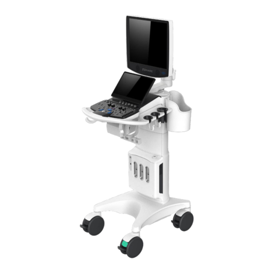
System Overview Major System Assemblies Figure 4-1 ZS4 System ZS4 Service Manual Page 36 of 279... -
Page 40: User Interface Overview
User Interface Overview Figure 4-2 ZS4 Full Featured User Interface is shown above. Figure 4-3 - ZS4 Special Procedures User Interface is shown above ZS4 Service Manual Page 37 of 279... - Page 41 USER INTERFACE FUNCTIONS Note: Not all controls are available on the SP user interface. Features and functions not directly accessible via hard key are still available however via menus. Sign Description Setup Used to bring up the SYSTEM SETUP configuration menu. F1 –...
- Page 42 Frequency Enables increasing/decreasing transmit frequency. Select Toggles between active modes such as dual pane and caliper as well as image manipulation. Store1/2 Press to store the displayed image to the storage device (programmable). Provides primary functionality and navigation such as selecting, calculation, setting, moving, or editing etc.
- Page 43 Trackball Used for positioning the cursor, defining size/position of ROI in color mode, positioning measurement tools, reviewing cine-loop images and navigating form/tables/worksheets/reports. Priority Press to cycle through different menus the Priority key while multiple imaging mode menus are available, for example M, B and Cine modes.
-
Page 44: On-Screen "Dashboard" System Status Icons
On-Screen “Dashboard” System Status ICONs If the system is equipped with the on-board battery option, a battery icon will be displayed in the lower-left hand corner of the LCD display of the ZS4. Icon Function Status Description Battery System running on AC Power, and Battery Status is fully charged. -
Page 45: Accessory Components
Icon Function Status Description Wireless Wireless Network transfer has an error Network (Re-Queuing of job, etc.) preventing transfer. Wireless Wireless signal strength: 1% – 33%. Network Wireless Wireless Network Wireless signal strength: Network 34% – 66%. Wireless Wireless Network Wireless signal strength: Network 67% –100%. -
Page 46: Rear I/O Panel
ZS4 systems. They have been verified for optimum reliability and performance. If you purchase your own USB memory stick, Mindray/Zonare is not responsible for any errors associated with file corruption or file-transfer time increases. -
Page 47: System Uncrating & Installation Procedures
If any problems are found, make notes of any discrepancies and immediately report to the shipping carrier and to Mindray/Zonare’s shipping department representative. All installation and set-up of equipment should be done following this official Mindray/Zonare product installation procedure. - Page 48 Banding strap Figure 5-1 -ZS4 5. Lift off the top cover portion of the main cardboard shipping container, and set aside. Figure 5-2 -ZS4 6. Remove the small boxes containing the transducers (a maximum number of 4) and the small box containing accessories from the inner storage box area (resting atop the ZS4 System).
- Page 49 8. Grasping the sides, slide the cardboard main shipping box upwards, exposing the ZS4 system. Continue lifting until the cardboard box can be completely removed, and set aside. Figure 5-4 -ZS4 9. Remove the protective foam in the back of the display, and pull forward the upper foam of the display Figure 5-5 -ZS4 10.
- Page 50 Velcro Figure 5-6 -ZS4 11. Remove the accessory box, containing front cover and left/right storage box, upon the front support board. Accessory Figure 5-7 -ZS4 12. Remove the puller strap around the front support board according to the puller strap indicator label, and remove the front support board.
-
Page 51: Mechanical Inspection
Ensure the LCD display monitor rotates and adjusts properly • Ensure the ZS4 module is securely attached in the Cart. • Immediately report any mechanical discrepancies to Mindray/Zonare. • System Installation 1. Check to ensure all peripherals, software level, and serial numbers correspond with sales order. -
Page 52: Zs4 System Verification
DOCKING MODULE INTO ZS4 ULTRASOUND SYSTEM 1. Place the Module in the docking area on the cart. 2. Slide the module to the back, ensuring the docking connector is properly aligned. 3. Latch in the side locking mechanisms to secure the Module in place. 4. - Page 53 1. Verify the socket of the AC power cord is fully inserted into the inlet in the back of the cart. 2. Connect the plug of the AC power cord into a Hospital Grade receptacle. 3. Make sure the AC Main Circuit Breaker on the ZS4 System is in the “1” (ON, pushed in on the LEFT) position (see illustration below).
- Page 54 On/Off Button Status • The Green backlight for the button will begin to flash as the system boots-up. • Once the system is booted, the Green Backlight will be steady On. • Abnormal conditions will be indicated with an Amber colored backlight. 5.
-
Page 55: Setup
Setup Setup is designed to provide customization of the system configuration settings to meet customer needs and preferences. It is recommended to back up the setup (system) configuration to the cart hard drive, as well as an external USB device. To enter Setup, press the Setup key on the User Interface. - Page 56 System Setup Description of Setup Menu Configure: Institution information Region Language Time Zone, Date Format, and System Date/Time settings Configure: Patient Banner Display Content General system behaviors Status after Freeze General Restart/End Exam Automated image storage/deletion options TRI review Font settings Pt Info Configure the items to be displayed on the Patient info page.
- Page 57 Preset Management Description of Setup Menu Setup Configure category and preset combinations that will be available for each transducer. Enable / Disable Category can be disabled entirely as well as individual presets. Customization Assign Presets to touch screen controls for easy access Select User Presets for deletion by transducer and category.
- Page 58 Stress Echo Setup Description of Setup Menu Create, edit, import, load, and delete SE protocols Protocol Select and configure onscreen labels, ROI type, and default WMS type. Maintenance Customize or reset clip triggers. DICOM Setup Description of Setup Menu Configure a DICOM destination including AE Title, port, transfer specifics/ Storage options, and image/clip specifics/options including Transducer Tracking.
- Page 59 Key Config Description of Setup Menu ‘B-Mode’ - strip all modes and maintain only frozen B-Mode image ‘B-Mode Home Live’ – regardless of current status, pressing B knob results in a live 2D image Trackball speed Key Configuration – Default vs Legacy touch screen display and SP UI button configuration options Configure: Capture type - Live (Clip vs Still) &...
- Page 60 Peripherals Setup Description of Setup Menu Configure sleep and shutdown behavior when on battery and external power. Power Save Enable/disable a low battery warning and status level when it should display. Backup / Restore Description of Setup Menu Backup and Restore function for Preset and System configuration files (full or partial) to and from a USB device and/or the cart SSD.
-
Page 61: Security
Security Access Control The system supports two user types: system administrator and operator. Administrator The system administrator can access all function modules, and view all patient data, such as patient information, images and reports, etc. Only one administrator is configured by default. -
Page 62: Enabling Location Access Control
Enabling Location Access Control The “Location” option supports cases where a User has a need to physically move their system from one facility (location) to another on a regular basis. This function addresses cases where this movement includes connecting to a unique network at each location, for sending to DICOM devices, and those network connections consist of different IP addresses and/or target DICOM devices. -
Page 63: Enabling Account Access Control
Enabling Account Access Control The system administrator can preset the access controls, that is, whether an operator has the right to access data in the system. Access control only can be set by the system administrator. Setting access control: Open the “Access Control” page using the path: [Setup] → [System] → [Security]. is selected, you must be authorized before accessing the data, and you can configure password policy and LDAP, and change password. -
Page 64: Local Privilege Management
Click [Change User] to bring up the Logon dialog box. Select the logon type, and user name in the drop-down list. Enter the password and click [Logon] Lock the system Click the in the bottom-left corner of the screen to bring up the dialog box. Select [Lock Machine] and the system is locked. - Page 65 Click [Add] to bring up the dialog box. Enter the user name and password, confirm password, and select or deselect the check box from the privilege list. Users can only access the function module with assigned privilege. Click [OK] to confirm the setting and exit the dialog box. The new user and the privilege will appear in the User List.
- Page 66 Modify Passwords The system administrator can modify all user passwords. The administrator password is empty by factory default. You can set this password. An operator can only modify his/her own password. There are two ways to modify passwords: on the “Security” page or in the “Manage Session” dialog box. ...
- Page 67 Configure password policy Turn on the access control function and log in to the system as Administrator before you configure the password policy. 1. Open the “Security” page using the path: [Setup] → [System] → [Security]. Click [Password Policy Config]: Parameter Description Remark...
- Page 68 Parameter Description Remark password for 5 times within 60 minutes, the account is locked, and the user can log Lockout Set the duration after an in to the system only period account is locked. after 60 minutes. Other users with unlocked accounts can still log in to the system normally.
- Page 69 Parameter Description Remark Enable strong password to improve security. If the strong password is enabled and you log in to the system with the account that is added before the strong password is enabled, the system prompts a warning message to inform you whether your password conforms to the password policy.
-
Page 70: Ldap Privilege Management
LDAP Privilege Management Turn on the access control function and log in to the system as Administrator before you edit privileges for the LDAP (Lightweight Directory Access Protocol) users. 1. Enter [Setup] → [System] → [Security] → [LDAP Config]. 2. Enter the server address in the field box after accessing the network. 3. - Page 71 Parameter Description Set days to keep the cached passwords in the local system Users can log in to the server even without accessing the network within the setting days. Empty: the passwords are kept Days to keep cached password in the local system permanently.
-
Page 72: User Field Name
User field name 1. Enter [Setup] → [System] → [Security] → [LDAP Config]. 2. Select [Use user field name] to customize the user field name. After that, the members and privileges cannot be edited. 3. Enter the user field name in the field box of the "User field name" (the user field names are configured in the LDAP server. -
Page 73: Enable Encryption
2. In the Logon screen, scan a barcode that complies with the regex rule, and the system automatically enters the LDAP Logon page and display the User Name. After that, enter the password, and you can log in to the system. Enable Encryption This function enables users to encrypt data that is stored in the hard disk. -
Page 75: Patient Information Management
Patient Information Management You can start a patient exam in the following situations: New patient information: to start a new patient exam, patient information must first be entered. New exam: to start a new exam for patient who is already registered, the recorded information can be obtained through either Archive or Worklist. -
Page 76: New Patient Information
Click [Quick Register] on the screen to save the patient information quickly and return to the main screen. The system supports image scan and measurement without patient information. New Patient Information The Patient Info screen is shown as follows: Place the cursor onto the targeted box. - Page 77 Enter patient name through the keyboard. Gender Select Male, Female or Unknown for patient gender in the drop down list. Date of Birth Or, click to select the date and click [OK] to finish. Auto generated age: once the DOB is obtained, the system can display an auto-generated age in the field box, the unit can be “Years”, “Months”...
- Page 78 Exam Type Information Description Alanine transaminase. Height Weight Calculate gestation age (GA) and estimated delivery date (EDD) based on last menstrual period (LMP), in vitro fertilization (IVF), basic body temperature (BBT), previous exam date (PRV). Select LMP, IVF, PRV, BBT, or EDD from the drop-down list;...
- Page 79 Exam Type Information Description LMP (last menstrual period) Gravida: times of pregnancy. Para: times of delivery Gravida: times of Extrauterine pregnancy abnormal pregnancy. Abort: times of abortion Ectopic Essential female hormone and ovulation information Height Weight BSA body After the height and weight are inputted, the system will surface automatically calculate the BSA based on the formula.
- Page 80 Exam Type Information Description BP(R) (blood Input right blood pressure. pressure) Height Weight Serum (Urology) PPSA coefficient Height Small Parts Weight Height (Pediatrics) Weight Height Breast Weight 3. Operating Information Accession: refers to exam number used in DICOM. Attd.
-
Page 81: Retrieve Patient Information
Retrieve Patient Information ARCHIVE The patient data can be accessed via the “Archive” of the system or USB memory device. Keyword search is available to locate certain studies. Patient data includes basic patient information, exam information, image files and reports. Functions within “Archive” include: search, view, backup, send, restore, delete and export of patient data. - Page 82 Select “Find in results”, the system will search the keyword based on the existed searched results. Select "Teaching Exam", the system will search the exam that is send to teaching exam. 4. Select the desired patient information in the list, and the system pops up the following menu.
- Page 83 Send Exam The system supports sending data to external memory devices, print, or DICOM. You can use this function to export the exam data to external devices and then import to PC or restore to the ultrasound system to review the data. Select the patient record, click [Send Exam] in the menu to send exam data or images of the selected record.
- Page 84 Backup Exam Select the patient record, click [Backup Exam] in the menu to backup exam data or images of the selected record. 1) Select a destination. 2) Select whether to remove from local HD after Backup: if "Remove Exams" is selected, the patient information and images are removed;...
- Page 85 [Select All Exams]/ [Deselect All Exams]: click [Select All Exams] to select all the patient data listed. Then the button changes into [Deselect All Exams], you can cancel all the selections by clicking [Deselect All]. [Exit]: click to exit Archive. WORKLIST/HL7 ENQUIRY Tips: worklist is an optional function.
- Page 86 • Select HL7 server. Search via patient ID, patient name. b) Click [Query]. Scheduled patients found within the search criteria are displayed in the lower part of the screen. After the first query, you can perform the second query based on the •...
-
Page 87: Dicom/Hl7
DICOM/HL7 NOTE: Before using DICOM, please review the ZS4 DICOM conformance statement. This chapter is confined to the preset, connection verification and DICOM services of the DICOM-configured ultrasound machine, not including SCP configurations like PACS/RIS/HIS. The DICOM package is optional, so the description here is only applicable for the system configured with the DICOM package. -
Page 88: Dicom Preset
DICOM Preset NETWORK PRESET Refer to "11 Network" for details. DICOM LOCAL PRESET Enter the DICOM local preset screen using the path: [Setup] [DICOM]. Enter AE Title, Port and PDU according to the actual situation, then click [Save] to exit the screen. Setting items are described in the following table. Name Description Modality... - Page 89 Name Description Assign from In the worklist, search for exams with selected modalities. Modality Worklist Verify TLS Verify the effectiveness of the TLS certificates. Certificates Import TLS Import trusted certificates. Certificates Clear TLS Clear all certificates Certificates AE Title Application Entity title. Communication port, DICOM communication port.
-
Page 90: Service Preset
4001, 6000, 3001, 6555 cannot be set as the port. IP address should be the address of the remote server. Service Preset The DICOM Service screen is used to set attributes of Storage, Print, WorkList, MPPS, Storage Commitment, and Query/Retrieve, and HL7 Query. When the system is configured with DICOM basic function module, and installed with DICOM WorkList, MPPS, DICOM structured report, and DICOM query/retrieve modules, the corresponding preset can be found in DICOM Service screen. - Page 91 DICOM storage preset items are described as follows: Name Description After you set the server (s) in DICOM Preset screen, the Device name (s) will appear in the drop-down list, select the name of the storage server. Service Name Default is xxx-Storage, user-changeable. Application Entity title.
- Page 92 Name Description Set the storage mode for image and cine file: Parallel file: save the current file, and is ready for the Storage mode storage of the next file. Parallel frame: send the current frame, and is ready for sending the next frame. Select if files of images that are saved in DCM format Transducer through DICOM or DICOMDIR contain transducer serial...
- Page 93 rate is larger than the set value, the system will save the image files in a frame rate of the set value, and transfer in a frame rate of B mode. Images of PW/M/TVM/TVD mode (B image is frozen), the system will save/transfer the images files in frame rate of 6.
- Page 94 Name Description Range: 0-9. Number of retries, if it fails to send DICOM task Maximum Retries to the server. The number of retry attempts can be set here. Interval Time Reserved time. (Sec) Timeout (Sec) Refers to timeout during association establishment. Transport Layer Security.
- Page 95 Name Description Delete Click to delete the selected service in the service list. Service Click to verify if the two DICOM application entities are Verify List normally connected. Exit Click to exit the screen. WORKLIST SETTING 1. Select [Setup][DICOM][Set DICOM Service][Worklist] to enter the “Worklist” page.
- Page 96 Name NOTE After you set the server (s) in DICOM Server Setting screen, the name (s) will appear in the Device drop-down list, select the name of the Worklist server. Default is server-Worklist, and it can be Service Name modified. Application Entity title.
- Page 97 Name NOTE Click to add the Worklist service to the service list. Cancel Click to cancel the parameter setting. Select an item in the service list, change the Update parameters in the above area, and click [Update] to update the item in the service list. Click to delete the selected service in the Delete service list.
- Page 98 MPPS setting items are described as follows: Name NOTE After you set the server (s) in DICOM Server Setting, Device the name (s) will appear in the drop-down list, select the name of the MPPS server. Service Name Default is server-MPPS, and it can be modified. Application Entity title.
- Page 99 Name NOTE Cancel Click to cancel the parameter setting. Select an item in the service list, change the Update parameters in the above area, and click [Update] to update the item in the service list. Delete Click to delete the selected service in the service list Set the Worklist server as the default.
- Page 100 DICOM storage commitment setting items are described as follows: Name NOTE After you set the server (s) in DICOM Server Setting, Device the name (s) will appear in the drop-down list, select the name of the storage commitment server. Service Name Default is server-SC, and it can be modified.
- Page 101 QUERY/RETRIEVE 1. Select [Setup]DICOM][DICOM Service Setting][Query/ Retrieve] to enter query/retrieve page. 2. Select the device name. The select device is from the DICOM server. Type the information about AE Title and the port. Click [Add] to add the service to the Service list; ...
- Page 102 Name Description DICOM communication port, 104 by default. Here, the Port port should be consistent with that of the storage commitment server port. Maximum Reserved feature. Retries Interval Time(s) Reserved feature. Value: 5-60s, in increments of 5, and 15 by default. The connection is disabled if there is no image and Timeout information retrieving in 15 seconds after the user...
- Page 103 Select an item in the service list, and click [Delete] to delete the service. Select an item in the service list, and click [Default] to set the server to be the default service. HL7 service setting for Worklist is described as follows: Name NOTE After you set the server (s) in DICOM Server...
-
Page 104: Dicom Verifying
Name NOTE Refers to time after which the system will stop trying to establish a connection to the service. Timeout (Sec) Value: 5-60s, in increments of 5, and 15 by default. This function enables the ultrasound system to Listen Mode use the listen port for data receiving. -
Page 105: Dicom Services
DICOM Services If all the DICOM presets on the DICOM Service Preset screen are completed, you are ready for the Storage, Print, Worklist (HL7 Query), MPPS, Storage Commitment and Query/Retrieve applications. DICOM STORAGE DICOM Storage is used to send images (single-frame or multi-frame) or structured report to the DICOM storage server for storage. - Page 106 Click to select “DICOM” in the Target box on the left side, then select the DICOM storage server in the Storage Server box on the right side, and click [OK]. To send images using a shortcut key You can save single-frame images or multi-frame images to a DICOM server while saving to hard drive using a shortcut key.
- Page 107 1. Choose the storage option to Attach When Store Images, or Only Store SR. 2. Create new patient information or load the patient information. 3. Perform obstetric (gynecology, cardiac, breast or vascular) measurements: 4. Save the image or the cine. 5.
- Page 108 If there is an exam result in the report template, this type of exam should be performed. Sending the exam or archiving the exam can send the encapsulated PDF file. Unload DCM file The image can be unloaded to DCM format and send to the FTP server. 1.
- Page 109 To send images using a shortcut key You can send single-frame images to a DICOM print server while saving to hard drive using a shortcut key. Define the key (Store 1/Store 2/Print) in [Setup]->[Keys]->[Image Store/Print Buttons]. Set a default printer server. Press the shortcut key to send the image to the hard disk;...
- Page 110 Click [OK] to start sending. The system will send all the images stored in the exam record to the storage server. Meanwhile, it will send storage commitment to the storage commitment server. QUERY/RETRIEVE The query/retrieve function is used to query and retrieve patient exam records in a designated server.
-
Page 111: Dicom Media Storage
Click [Select All] to select all the patient records in the list. Click [Deselect All] to deselect all the patient records in the list. g) Click [Retrieve] to retrieve the patient records in the DICOM query/retrieve server to the local machine. h) Click [Exit]. - Page 112 Select the destination to “DICOM Media” and DICOM compression mode. You can select to delete the exam or the image after the backup. Click [OK]. The image from the current exam is sent to the external storage media in DICOM format. If the backup is successful, a tick will appear in the Backup list in the Archive screen.
-
Page 113: 10 Peripheral
10 Peripheral Print Service This screen is used to set up the printer and image printing. Enter [Setup]->[Peripheral]->[Print Service] in the preset menu to enter. Printer setting The printer settings include print service and print driver. Print Service Setting ... -
Page 114: Barcode Reader Configuration
Enter [Setup]->[Keys]->[Image Store/Print Buttons] and then select an appropriate printer service from the drop down list of the Network/USB Printer for the Store1, Store2, and Print buttons. Barcode Reader Configuration Enter [Setup]->[Peripheral]->[Barcode Reader Configuration] ZS4 Service Manual Page 110 of 279... - Page 115 Name Description Pos indicates the section sequence number of a 2D barcode. For example: Assume that the 2D barcode is composed of 3 sections: Smith, 123456, and Male in order, and the separator is semicolon ";". 1. Set [Multiple] as the default item and input semicolon ";"...
-
Page 116: Power Save
Name Description Operator ID or Attending Physician can be appended after being checked. For example, after scanning a 1D barcode of an Operator ID or Attending Physician, the obtained data is A, and A will be displayed in the "Operator ID" or “Attending Append Physician”... - Page 117 The two different categories of power operation mode configurations in this menu are: Title Definition Cart Battery Configuration of power saving action when the system is being operated without AC power applied. System will be running off the ZS4’s internal Z-PAK battery. External Power Configuration of power saving action when the system is running off AC wall power.
-
Page 119: 11 Network
11 Network Network Setup The “NETWORK” configuration menu allows for configuring the TCP/IP networking parameters that will be assigned to define the identity of the system on the hospital’s network. 1. Enters [Setup]-> [Network] -> [TCP/IP]. Using an alpha-numeric keyboard, enter in the required TCP/IP network configuration values/settings in the appropriate fields, as specified in the information previously provided in the “Pre-Installation Site Survey Form”, by the medical facility’s IT System Administrator. - Page 120 When power is applied to a correctly configured Quatech AirborneDirect device that is connected to the Ethernet port on the Mindray/Zonare system, it will require 30 to 60 seconds to detect and then associate with the user's wireless network.
- Page 121 4. Click [Save] to save the configuration. 5. Enter [Setup] [Network] [TCP/IP] again. 6. Click [Logon] to enter the "Wireless Login Configuration" page: 7. Enter dpac to the field of both the User Name and Password, and then enter 192.168.2.100 to the field of IP Address.
-
Page 122: Ftp Setup
12. Enter the wireless parameters assigned by the IT department. 13. Click [OK] to save the parameter configuration. 14. In the TCP/IP page, select "Obtain Automatically (use DHCP)", and click [Save] to exit the preset page. 15. After successful connection, a wireless network icon is displayed at the bottom left corner of the screen. -
Page 123: Qpath/Qview
1. Enter the required FTP configuration values in the fields of Service Name/IP Address/Port/User Name/Password. Parameters specified in the above figure are given as an example. 2. Select [Active] of the Data Transfer Mode. 3. Click [Add], and the FTP Service is displayed in the Service list. 4. - Page 124 The preset procedures are as follows: 1. Select [Enable Q-Path]. 2. Enter the server address in the field box of "Server Address". 3. Select an appropriate item from the drop-down list of "Category" 4. Select an exam mode in the left "Exam Mode" column. 5.
-
Page 125: Vpn
Parameter Description Accelerated Accelerates the movement speed of the trackball. Trackball Move Enable Direct Sets whether to open the Q-Path server through pressing Report the <Report> key. Sets whether to directly enter the Worksheet interface Worksheet Only after opening the Q-Path server. Sets whether to display the Signature field box in a worksheet. - Page 126 ZS4 Service Manual Page 121 of 279...
- Page 127 2. Enter the server IP in the field box, and click [Test IP] to test the IP address. After successful test, the system prompts the following message "Successfully passed VPN server IP test", and the [LogOn] button is highlighted. 3. Select a group from the drop-down list of "Select Group", enter the user name and password, and click [LogOn].
-
Page 128: 12 Functional Descriptions
12 Functional Descriptions System Capabilities 64-hardware - 128/192-synthetic channel system • Supports B-Mode, M-Mode, Color, Power Doppler, PW, ARFI • 19” full-screen, 1280 x 1024 resolution, Display • 13.3” 1920 x 1080 resolution touch screen • Discrete function user controls •... - Page 129 Figure 12-2-ZS4 CART BASE WITH CASTERS, P/N: 115-045914-00 • 115-031746-00 150mm total locking castor • 115-031572-00 150mm direction locking castor Figure 12-3-ZS4 CART POWER SUPPLY MODULE(FRU), ZS4 P/N: 115-078252-00 • VCart (power for module), +12V • VDock (Monitor, UI, Printer), +12V •...
- Page 130 Figure 12-4-ZS4 CONTROL PANEL(FRU) P/N: 115-078249-00 Control Panel-SP(FRU) P/N: 115-078250-00 • Trackball assembly • DGC controls • Discrete functional controls Figure 12-5-ZS4 Full Figure 12-6-SP ZS4 Service Manual Page 125 of 279...
- Page 131 19 INCH DISPLAY ASSEMBLY (FRU)OVERLAY ZS4 P/N: 115-091503-00 19 INCH DISPLAY ASSEMBLY (FRU)OVERLAY ZS3 ELITE P/N: 115-091504- 19 INCH DISPLAY ASSEMBLY (FRU)OVERLAY ZS3KP ELITE P/N: 115-091506- • System display • Speakers • Internal MIC • Overlay Figure 12-7-ZS4 DISPLAY SUPPORT ARM KIT, ZS4 P/N: 115-046667-00 •...
- Page 132 Figure 12-8-ZS4 TOUCH SCREEN ASSEMBLY (FRU) P/N: 115-078248-00 • 115-076914-00 Touch Screen Assy, ZS4 Figure 12-9 Touch Screen CART BATTERY MODULE(FRU) LITHIUM BATTERY, P/N: 115-078251-00 Figure 12-10-ZS4 ZS4 Service Manual Page 127 of 279...
- Page 133 BRAKE MECHANISM - CASTER The system has 4 casters in 2 different types: 3 total locking casters (the left black one as shown in the following figure) and 1 direction locking caster (the right green one as shown in the following figure). Figure 12-11-ZS4 ...
-
Page 135: 13 System Diagrams
13 System Diagrams ZS4 Service Manual Page 129 of 279... -
Page 136: Power Block Diagram
Power Block Diagram Figure 13-1-ZS4: Power Block Diagram ZS4 Service Manual Page 130 of 279... -
Page 137: Cabling Diagram
Cabling Diagram Figure 13-2-ZS4: Cabling Diagram ZS4 Service Manual Page 131 of 279... -
Page 138: System Block Diagram
System Block Diagram Figure 13-3-ZS4: Overall System Block Diagram ZS4 Service Manual Page 132 of 279... -
Page 139: 14 Peripherals & Accessories
14 Peripherals & Accessories Black & White Printer The procedure provides instructions to install and setup the SONY UP-D711MD, Sony UP-D897MD, and Sony UP-D898MD_X898MD Black and White printer on the ZS4 system Figure 14-1-ZS4 Prior to beginning the initial mounting/installation, ensure the system is powered-down (Backlight for power On/Off button should be dark). - Page 140 3. Use a Philips screwdriver to install the four (4) 33104-00 screws that attach the printer/bracket assembly to the user interface base. Figure 14-3-ZS4: Printer Bracket Mounting to ZS4 Cart 4. NOTE: The printer comes out of the box with M3 Phillips head screws installed in its threaded mounting holes, as placeholders or thread protectors.
- Page 141 Figure 14-5-ZS4 6. Using a Philips screwdriver, install the four (4) 33215-00 flat head screws (provided in the kit), through the holes in the mounting bracket and into the four threaded holes in the printer, as shown below. Figure 14-6-ZS4 7.
- Page 142 Figure 14-7-ZS4 Operator Controls Figure 14-8-ZS4: Operator Controls (UP-D711) Power ON/OFF Switch Printer Lamp – Lights while printing ZS4 Service Manual Page 136 of 279...
- Page 143 Feed Button – Hold down to feed paper. The paper will only advance while the button is pressed. Paper Lamp – Lights when tray is empty or paper not aligned correctly. Alarm Lamp – Lights when door is open or problem with printer. Open Button –...
- Page 144 Figure 14-9-ZS4 4. Power-On the system. 5. Turn the printer on by pressing the button. 6. Press and hold the Open button to extend the paper tray. 7. Place the paper roll into the tray and make sure the paper extends out through the opening.
- Page 145 8. Make sure the paper is set straight. High gloss paper is recommended for optimum quality print. 9. Close the door and press until it locks. Setup Procedure For details about printer settings, please refer to "Print Service". Print verification: 1.
-
Page 146: Color Printer
NOTE: Refer to the SONY UP-D711MD Operators Manual, for detailed information on proper operation of this device. Color Printer INSTALLATION NOTES: SPECIAL NOTE The Sony UP-D25MD Color Printer is oversize and is therefore not a peripheral that can be “mounted” on ZS4 system. A separate external location (rolling cart, tabletop, etc) must be made available for storage of this printer. -
Page 147: Pedal Footswitch
12. Verify a printed image is produced on the UP-D25MD when the “Print” key on the user interface is depressed. NOTE: Refer to the SONY UP-D25MD Installation Procedure (P/N S00119), or Operator Manual from SONY, for detailed information on proper operation of this device. Pedal Footswitch A remote 2-pedal footswitch is available for purchase as an option for use with the ZS4 system. - Page 148 2. Use a screwdriver to install the 1 Pan head screw M4X12 that attaches the Gel warmer cable to the Stem weldment Pan head screw M4X12 Gel warmer cable Figure 14-11-ZS4 3. Remove the eight (8) screws underneath the UI and disconnect and remove the UI, thread the Gel warmer cable through the punch hole of UI interface base and connect 4-pin connector side into the rightmost port of the power distribution strip Remove the eight (8) screws and...
- Page 149 Gel warmer cable connect port Figure 14-13-ZS4 4. Wind a circle and tie the tail of the Gel Warmer cable and printer USB cable. Wind a circle and Tie the tail of the Gel Warmer cable and printer USB cable Figure 14-14-ZS4 Notes: Screw tightening torque: M4: 6-7 kgf.cm For upgrade gel warmer...
- Page 150 2. Paste 70-80mm length of PVC electric insulation tape on the edge of the Stem weldment Paste PVC tape Figure 14-16-ZS4 3. Use a screwdriver to install the 1 Pan head screw M4X12 that attach the Gel warmer cable to the Stem weldment Pan head screw M4X12 Gel Warmer cable Figure 14-17-ZS4...
- Page 151 Printer power cable Gel Warmer cable Figure 14-18-ZS4 4. Connect Gel power cable to printer power cable. Push them back to the inside of UI interface base. wind a circle and Tie the tail of the Gel Warmer cable and printer USB cable (If there’s no printer installed) Wind a circle and Tie the tail of the Gel Warmer...
- Page 152 Upper bracket of Gel warmer Figure 14-20-ZS4 2. Aligning with the rib of the upper bracket, assemble the bracket cushion onto the upper bracket. Bracket cushion Align with the rib Figure 14-21-ZS4 3. Screw the lower bracket into the upper bracket till the marks aligned. (Fig.5C, 5D) ZS4 Service Manual Page 146 of 279...
- Page 153 Punch hole of Gel warmer cable Lower bracket Figure 14-22-ZS4 Marks aligned Figure 14-23-ZS4 4. Thread the Gel warmer cable through the punch hole of the lower bracket, buckle the Gel warmer downward. (Fig.5E, 5F) Gel warmer Figure 14-24-ZS4 ZS4 Service Manual Page 147 of 279...
- Page 154 Figure 14-25-ZS4 For upgrade gel warmer holder Auxiliary material: Cable Tie, and PVC electric insulation tape 1. Tie Gel warmer cable together with Monitor power cable on front of the Stem weldment. Replace telescoping cover. If printer is optional, tie printer power cable and printer USB cable.
-
Page 155: Zs4 Intracavity Probe Holder
Gel warmer cable Cable tie needs to thread through the mounting hole in connector of Gel warmer Cable tie Figure 14-27-ZS4 ZS4 Intracavity probe holder The intracavity probe holder is an optional module of the system for supporting the intracavity probe. OVERVIEW Figure 14-28-ZS4. - Page 156 Figure 14-29-ZS4. Intracavity probe holder bracket side view The front view of the intracavity probe holder is shown in Figure 14.29. In the figure, 1 is the intracavity probe holder part 1, and 2 is the intracavity probe holder part 2. Figure 14-30-ZS4.
- Page 157 HOW TO INSTALL THE INTRACAVITY PROBE HOLDER 1. Assemble the intracavity probe holder part 2 into the intracavity probe holder part 1 from top to bottom in the direction of the arrow. Figure 14-32-ZS4. Diagram of the assembly of the intracavity probe holder part 1 and part 2 2.
- Page 158 Flange Buckle Figure 14-34-ZS4. Diagram of the assembly of the intracavity probe holder 4. For machine that has been configured with a storage basket, the storage basket pad needs to be first mounted to the basket flange and the basket is secured to the hook of the intracavity probe holder.
- Page 159 DISASSEMBLING THE INTRACAVITY PROBE HOLDER Gently push the bracket handle position in the direction of the arrow until the buckle is released from the control panel base flange and then remove the bracket from bottom to top. Figure 14-35-ZS4. Diagram of the removal of the intracavity probe holder ZS4 Service Manual Page 153 of 279...
-
Page 161: 15 Software Procedures
15 Software Procedures Backup Operations Backing up imaging presets and system configuration: 1. If there are customized imaging presets and system configuration that are desired to be backed up, insert a target USB stick for backup into the USB port on the front or rear of the system. -
Page 162: Restore Operations
• System Configuration: The backup SYSTEM operation provides capability for selecting the granularity for the specific parameters that will (or will not) be used during the Backup operation. The selectable options, and a description of what parameters are included in each item, are listed below: ... - Page 163 User Presets (3 Options) Retain customer imaging parameters and incorporate factory enhancements (Suggested) Keep all customer imaging parameters. Do not incorporate factory enhancement (Recommended) Retain customer preset names but set ALL imaging parameters to factory setting. Preset linkages: Preset Linkages allow for determining whether specific transducer type/exam type presets are linked directly to specific annotation and custom worksheets/report (or not), as part of the Preset “RESTORE”...
- Page 164 2. Restore according to exam type Select [Exam Type] in the "Restore Imaging Presets" region to enter the "Load Data" screen, select the data to be restored, and then the system enters the following page: Select a desired transducer and exam types (you can select 1 or more exam types), and then click [Restore] to begin the restoration.
-
Page 165: Diagnostic Panel Operations
Annotation/Body Patterns (User Annotation and customer Body Markers) Programmable Keys (Program keys; Image Store/Print button; Store) Protocols (Including Stress Echo) Calculation Setup (User Calculation setup parameters) Location Manager (preset information, including DICOM, FTP, Print etc.) ... - Page 166 • NOTE: The majority of the functions in the User Diagnostics Panel involves the use of an internet connection between the ZS4 system and Mindray/Zonare’s network server for uploading or downloading files. Performing any of these procedures requires contacting Mindray/Zonare Technical Support to received specific information on IP address and log in used to make the connection.
- Page 167 Parameter Description The current system software revision and system serial System number appear here. Click the Details button for PC board revision information. License info: display the currently configured features and transducers. License Update: update a new license through the USB disk containing a license file ...
- Page 168 Store the logs to local disk Store Current Logs Store the image to local disk Store Image Clear all logs or clear logs by date Clear Logs Export all logs or export logs by date (this button is active Export Logs only after an USB disk is inserted to the ultrasound system) ...
- Page 169 The additional functions available beyond the main page of the User Diagnostic Panel, in these three sub-menus, are as defined below: SETTINGS 1. Click Settings on the User Diagnostic Panel. 2. Select the desired settings and click [OK]. ZS4 Service Manual Page 162 of 279...
- Page 170 FTP Address 12.40.200.87, user name LOGS and password support are supplied by Mindray/Zonare. Click Ping button to test. Select Auto Logging to have system automatically send logs.
- Page 171 MAINTENANCE 1. Click Maintenance on the User Diagnostics Panel. 2. Select the desired features and click [OK]. Parameter Description Select Upgrade Firmware (CartFirmware) to update Cart Power Board power supply firmware. Select Battery Status to view cart battery values ZS4 Service Manual Page 164 of 279...
- Page 172 • VWALL:24V +/- 5% (only when AC present) • Charging State: o OFF ------------------------------------- 0 o SOFT_START ------------------------ 1 o TOP_OFF ----------------------------- 2 o RAPID_CHARGE ------------------- 3 o TRICKLE ----------------------------- 4 o MAINTENANCE -------------------- 5 o COOL_DOWN ----------------------- 7 o DRIVE_DONE ----------------------- 8 •...
- Page 173 Allows (if checked) or disables (if unchecked) access to Enable Debug Console the System Console window (ALT-GR / Shift / Z keys) for entering low-level commands for service. Lock-out offered due to same key combination used for international character text entry during normal use. ...
-
Page 175: Care And Maintenance
• To avoid electrical shock, do not remove covers other than the scanner module cover. • For servicing, contact Mindray/Zonare Technical Support only. Failure to do so may void your warranty or service contract coverage. To safely use and maintain the system: •... -
Page 176: Basic System Care
• Do not immerse the battery in water or allow it to get wet. • Do not put the battery into a microwave oven or pressurized container. • Use only Mindray/Zonare batteries. • Store the battery between 32F and 120F (0 and 50C). - Page 177 Use a soft dry cloth to clean the surface of the control panel (including the keys, knobs and sliders). If the control panel is dirty, moisten the soft cloth with a little mild soapy water and wipe away any stains. Use another soft dry cloth to remove any moisture and allow all hard surfaces to completely air dry.
-
Page 178: Transducer Maintenance
Be sure to check pins before connecting a transducer to the ZS4 system. If pins are bent, broken, or missing, do not use the transducer and call Mindray/Zonare Technical Support. ZS4 Service Manual... -
Page 179: System Check
Figure 16-1-ZS4 System Check Follow the procedures below to verify the correct operation of the system. Mechanical and Visual Inspection 1. Verifying System Display 1.1. Verify the Display is securely mounted to the system. 1.2. Turn Display left and then right. Verify Display moves freely in both directions. 1.3. - Page 180 3. Verifying Wheel & Brake Operation 1.1. Visually inspect the wheels and wheel brake for damage. 1.2. Verify brake operation. Engage the brake on each wheel and verify that they lock. 1.3. Release locks and rotate. 1.4. Verify straight-line wheel track locking by engaging the straight-line wheel locks. 1.5.
- Page 181 1.6. Use the trackball to enlarge the ROI to the lower right corner of the image. This will maximize the size of the box. 1.7. Turn the color gain to the maximum value of 100 as displayed on the main monitor.
- Page 182 6. Verify Printers (if applicable) 1.1. Acquire the desired ultrasound image. 1.2. Press the Freeze button to obtain a still image. 1.3. Press the Print button on the cart to trigger a print of the current onscreen image to the Sony B/W printer, or Sony Color Printer. 1.4.
- Page 183 shall be performed in an environment that is free of significant interference noise sources for the ultrasound product. The environment includes avoiding use of AC power outlets on lines shared by other electronic equipment in the vicinity. 4. Scanning techniques: put the probe on the acoustic window of the phantom, without spacing or pressing.
- Page 184 2. Depth of Penetration Verification Depth of Penetration The maximum depth of penetration should remain constant over time. Variation indicates performance degradation. Method of Testing The maximum sensitivity or depth of penetration is determined by measuring the depth in the phantom at which the usable echo information in the far field first disappears.
- Page 185 1.8. Press the Freeze key to stop imaging. 1.9. Press the Optimize key to optimize tissue gain levels. 1.10. Using the targets in the ultrasound phantom, determine the Penetration Depth (mm), where the target pins in the far field first disappear, for the selected transducer.
-
Page 187: Preventative Maintenance Forms
17 Preventative Maintenance Forms ZS4 Service Manual Page 178 of 279... - Page 188 Ultrasound System PM Report (Standard) INFORMATION Account Name Model Name Model Serial Number Software Version Work Order Number TEST EQUIPMENT Leakage Tester Make Simulator Make Leakage Tester Model Simulator Model Leakage Tester SN Simulator SN Leakage Tester Cal. Simulator Cal. Due Due Date Date ELECTRICAL SAFETY...
- Page 189 Signature Ultrasound System PM Report (Comprehensive) INFORMATION Account Name Model Serial Model Name Number Software Version Work Order Number TEST EQUIPMENT ECG Simulator Leakage Tester Make Make ECG Simulator Leakage Tester Model Model Leakage Tester SN ECG Simulator SN Leakage Tester Cal. ECG Simulator Cal.
- Page 190 Geometric Geometric Pass Fail Pass Fail Accuracy(axial) Accuracy(lateral) TRANSDUCER #2 Probe Model Probe SN Physical / Mechanical Depth of Pass Fail Check Penetration(cm) Uniformity(element Uniformity(brightness) Pass Fail Pass Fail dropout) Geometric Geometric Pass Fail Pass Fail Accuracy(axial) Accuracy(lateral) TRANSDUCER #3 Probe Model Probe SN Physical / Mechanical...
- Page 191 Additional Comments: Name Signature Date ZS4 Service Manual Page 182 of 279...
-
Page 193: 18 System Troubleshooting
18 System Troubleshooting Many malfunctions are caused by a routine problem, such as power disconnection or the maladjustment of basic imaging or peripheral device (LCD display) controls. Before calling Tech Support, please perform the following troubleshooting procedures on the affected component(s). The troubleshooting information in this section is intended to assist in diagnosing potential causes of a variety of system problems. - Page 194 ZS4 Service Manual Page 184 of 279...
- Page 195 Additional information (e.g., Details, “Module”, “Revision”, etc.) CHECK POINTS VOLTAGES When the system is connected to AC #1: SOLID ON; #3: SLOW BLINKING Figure 18-1-ZS4 When the system is fully booted up. ZS4 Service Manual Page 185 of 279...
- Page 196 #1: SOLID ON; #4-7: SOLID ON AFTER COMPLETE BOOT UP. #3: FAST BLINKING AT FIRST THEN SOLID ON. Figure 18-2-ZS4 SCREEN CAPTURES AND LOGS For details, please refer to "Diagnostic Panel Operations". EXPORT LOGS AND SYSTEM DATA Obtain Logs In case you can still enter Doppler user interface. 1.
-
Page 197: Troubleshooting
Caution: Bent, broken, or missing pins on the transducer connector may cause poor image quality, including possible mirror image artifact. Be sure to check pins before connecting transducer to the Mindray/Zonare ultrasound system. If pins are bent, broken, or missing, do not use the transducer and call Mindray/Zonare Technical Support. - Page 198 Figure 18-4-ZS4 Figure 18-5: Transducer Connector Pin Damage – (Example) Inspection of Transducers 1. Routinely inspect transducers for the following problems. Signs of wear or damage to the housing, cable, etc. • • Cracks in case or transducer face. • Cuts or gouges on any part of the transducer, including transducer face, case, cable, and connector.
- Page 199 POWER-ON PROBLEMS System fails to power on 1. Ensure that the AC power is connected to a wall outlet. 2. Ensure the AC power cord is fully seated in the socket on the rear of the cart. 3. Ensure that the circuit breaker (located in the lower-left of the rear panel) is pressed down in the “1”...
- Page 200 The system cannot boot up Check: Check AC LED (#1) 1. Power cable is properly connected lights normally? 2. breaker is switched on. Press power button, Check: check Interlock LED the module cover is correctly normally? installed? Disconnect the AC cable, wait Press power button, 30s, reconnect the AC cable, check #5/6/7 LED solid?
- Page 201 STATUS Definition Solid: System has AC Mains applied and 5V standby is active. “AC Present” OFF: No AC detected, circuit breaker off. OFF: No battery installed, or completely depleted, or system is being used on battery. “Battery” Solid: Battery is charging or fully charged. “Controller Slow Blinking: When power button is pressed...
- Page 202 When the cover is off or doesn’t engage the interlock switch, power button LED status is solid amber. When the cover is correctly seated and the cart is not turned on, LED is off. Figure 18-6-ZS4 Power button LED blinks when the power button is pressed. When the system has booted to imaging, it turns solid green.
- Page 203 • Temporarily connect the power cord of the peripheral to a local receptacle, and test for operation of the peripheral. • If the peripheral fails to power on after these steps, contact Mindray/Zonare Tech Support. Sony B/W printer fails to print •...
- Page 204 • If the printer fails to print after these steps, contact Mindray/Zonare Tech Support. TRANSDUCER PROBLEMS Transducer not recognized by system (no B-mode imaging) • To ensure a positive connection, disconnect the transducer and reconnect it. • Inspect the metal contact pins on the transducer connector for any residue or damage.
- Page 205 • To ensure the quality of the gray scale resolution of the LCD display, use the gray scale test pattern (via the Diagnostic menu) that is available. Ensure that all shades can be visualized, making small adjustments to brightness and contrast from factory defaults, as required, to see all intensities.
-
Page 206: System Status Led & Error Code Definitions
• Select the Device List for the destination and hit “Ping”. If it fails, check IP address and make sure DICOM server is setup and active on the network. If it still fails, check with IT to confirm information entered is correct. •... - Page 207 STATUS Definition Solid: System has AC Mains applied and 5V standby is active. “AC Present” OFF: No AC detected, circuit breaker off. OFF: No battery installed, or completely depleted, or system is being used on battery. “Battery” Solid: Battery is charging or fully charged. “Controller Slow Blinking: When power button is pressed...
- Page 208 Error Code Subsystem Message for Error log User Error Message Action on Action "IOE30A BATT STATUS 0xa6040402 CBKEY30A Batt Status Retrieval Error RETRIEVAL ERROR" Continue "Cart Device Initialization Error. If error persists call 0xaf034005 HSSL_LINK ostr.str service." Continue "System fan Error: THERMALSER Please shutdown 0xaf050401...
- Page 209 Error Code Subsystem Message for Error log User Error Message Action on Action "System Overheat THERMALSER Multiple Sensors over Warning: Finish exam and 0xaf05043c VICES warning Temperature Limit shutdown." Continue "MTP can't connect. Please disconnect and 0xaf0f0404 ACQCONTROL MPP can't connect reconnect."...
- Page 210 Error Code Subsystem Message for Error log User Error Message Action on Action "Internal System Error 0xe00a0410 IMAGING HV Fault has occurred. " Restart "Internal System Error 0xe00a0411 IMAGING HV Fault has occurred. " Restart "Internal System Error 0xe00a0412 IMAGING HV Fault has occurred.
- Page 211 Error Code Subsystem Message for Error log User Error Message Action on Action HV1N/HV2N/HVCW comparison error (bad "Internal System Error 0xe00a042f IMAGING command inputs) has occurred. " Restart HV limits check failed (bad "Internal System Error 0xe00a0430 IMAGING command inputs) has occurred.
- Page 212 Error Code Subsystem Message for Error log User Error Message Action on Action THERMALSER DIG_VSUPR over "System Temperature 0xef050424 VICES Temperature Limit exceeded." Shutdown THERMALSER XMT_V5NA over "System Temperature 0xef050425 VICES Temperature Limit exceeded." Shutdown THERMALSER XMT_VSUPR over "System Temperature 0xef050426 VICES Temperature...
- Page 213 Error Code Subsystem Message for Error log User Error Message Action on Action THERMALSER DIG_VSUPR Temperature "System Temperature 0xef050454 VICES Sensor Error Sensor Failure." Shutdown THERMALSER XMT_V5NA Temperature "System Temperature 0xef050455 VICES Sensor Error Sensor Failure." Shutdown THERMALSER XMT_VSUPR Temperature "System Temperature 0xef050456 VICES...
- Page 214 Error Code Subsystem Message for Error log User Error Message Action on Action "System Temperature THERMALSER RCV_AFE sensor Sensor Communication 0xef050468 VICES communication error Error." Shutdown "System Temperature THERMALSER RCV_CW sensor Sensor Communication 0xef050469 VICES communication error Error." Shutdown "System Temperature THERMALSER RCV_LV sensor Sensor Communication...
- Page 215 Error Code Subsystem Message for Error log User Error Message Action on Action Acq Programming Timeout Expired: Failed to complete "Internal System Error 0xef0f0403 ACQCONTROL programming sequence has occurred. " Restart "System Temperature 0xef0f0406 ACQCONTROL CW board over temperature Limit exceeded." Restart Operation Called with invalid "Internal System Error...
-
Page 216: How To Obtain Mac Address
How to Obtain MAC Address Tools: None Implementation: Obtaining the MAC address of wired network from system logs 1. Export Log Files 2. Find and open the “PMLogHistory.txt” file in the Log folder 3. The system MAC Address can be found a few lines underneath the “Postmortem” section of the logs (see image below). - Page 217 Obtaining the MAC address for Wireless Bridge 1. Press the Setup key on the control panel. 2. Click Network. 3. In the TCP/TP tab, click Wireless Details, a system prompt including the MAC address is displayed. ZS4 Service Manual Page 207 of 279...
- Page 218 4. Or Configure Wireless. Log in by using: username: “dpac” password: “dpac” 5. MAC address of bridge is located in the Status menu, see image below. Note: You can click [Factory Reset] if the wireless bridge login failed. ZS4 Service Manual Page 208 of 279...
-
Page 219: 19 Replacement Procedures
19 Replacement Procedures The procedures described in this section of the Service Manual should be performed ONLY by a Mindray/Zonare trained service personnel (Service Engineer, Biomed, etc.). Recommended Tools Size Where used Tool Description Screwdriver, flat blade, medium tip, 3mm blade, 6”... -
Page 220: Zs4 Module - Removal/Replacement
ZS4 Module – Removal/Replacement Identify the process for replacing the ZS4 Module. Overview of Procedure: • Remove Cosmetic Cover • Remove ZS4 Module • Replace ZS4 Module • Reassemble Cosmetic Cover • Verification of System Parts Required: • 115-051402-00 or 115-051400-00 ZS3 Module Equipment / Tools Required: •... - Page 221 Figure 19-2-ZS4 Remove ZS4 Module: 1. Flip open metal flaps on either side of the chassis. Figure 19-3-ZS4 2. Turn each flap counterclockwise 90° so that each clasp is released. Move each clasp out of the slots on the sides of the chassis. 3.
- Page 222 Figure 19-4-ZS4 Reassemble Cosmetics: 1. Align plastic covering so that transducer slots are aligned with transducer ports. The concave portion of the plastic covering should be partially covering the convex plastic tab on the cart. 2. Push plastic covering until it clicks into place. Verification of System: 1.
-
Page 223: Casters - Removal/Replacement
10. Test USB ports on Main Board panel. 11. Test and Verify Network Connectivity (if applicable). 12. Test and Verify USB Peripheral Connectivity and Functionality (if applicable). 13. Once verification is complete, return system to normal operation. Casters – Removal/Replacement Required Parts •... - Page 224 6. While supporting the display/display arm from swinging to the side, on a soft surface (carpet, etc.) tilt the Cart forward, until it is horizontal, resting on the two front push handles for support Caution: The Cart may be heavy and care should be taken while tilting forward, use two people if necessary to avoid injury.
-
Page 225: 19" Display - Removal/Replacement
19” Display – Removal/Replacement Required Parts • 115-091503-00 19 inch Display Assembly (FRU) Overlay ZS4 • 115-091504-00 19 inch Display Assembly (FRU) Overlay ZS3 Elite • 115-091506-00 19 inch Display Assembly (FRU) Overlay ZS3KP Elite Overview of Procedure • Removal of Display Assy •... - Page 226 Cable retention screw Figure 19-10-ZS4: Display Cover 5. Remove the (6) Phillips-head screws that are retaining the larger plastic display hinge back cover, and remove cover. Figure 19-11-ZS4 6. Remove the cover. 7. Disconnect the two cables on the upper right hand side (as shown below). ZS4 Service Manual Page 216 of 279...
- Page 227 Figure 19-12-ZS4 8. Remove the four (4) 9/32” Nuts with captive washers that attach the display to the metal hinge assembly. Support the Display Assembly while loosening the last bolt. 9. Tilt the top of the display towards the rear of the cart to support the LCD Display while removing the last screw.
-
Page 228: 13.3" Touch Screen - Removal/Replacement
2. Place AC circuit breaker, located at the rear of the system, in the “1” (On) position. Figure 19-13-ZS4 3. Ensure the system is docked in the cart. 4. Turn the system on. 5. Verify that the LCD display is functioning correctly by watching the boot sequence and verifying that normal imaging is displayed after system has fully booted. - Page 229 2. Place AC circuit breaker, located at the rear of the system, in the “0” (OFF) position. Figure 19-14-ZS4: System Circuit Breaker 3. Disconnect the main AC power cord from the rear of the system, or unplug from the wall source. 4.
- Page 230 Figure 19-16-ZS4 6. Take out the touch screen assembly upward and put it aside. Installation: 1. Install the touch screen assembly, rotate the touch screen to horizontal position and tighten the four cross-head screws; 2. Rotate the touch screen assembly to the vertical position, and reconnect the wo connection cables of the touch screen assembly to the sockets on the touch screen adapter board.
-
Page 231: Display Arm - Removal/Replacement
6. After the system is fully booted, the touch screen funcions normally, and communicates with the main unit normally. Display Arm – Removal/Replacement Required Parts • 115-046667-00 Display Arm w/o Cable • Small tie-wraps (2) Overview of Procedure • 19” Display - Removal/Replacement •... - Page 232 2. To remove the display cable from the netted stretch shielding through which it is routed (with other system cables) slide the netted stretch shielding together down its length, to cause the shielding to expand in diameter sufficiently to slide the Main Board end connectors out of the shielding.
- Page 233 5. Remove the four (4) 9/32” Nuts with captive washers that attach the display to the metal hinge assembly. Tilt the top of the display towards the rear of the cart to support the LCD Display while removing the last screw (See image below). Figure 19-21-ZS4 6.
- Page 234 Figure 19-22-ZS4 2. While gently pulling the video cable free from the system, remove arm assembly. Display Arm Installation: 1. Route the display cables and ground cable down into the chassis of the system, allowing adequate slack in the required areas. 2.
- Page 235 1. Reattach the display arm ground cable, and column ground cables to their mounting point on the bottom of the upper support plate, using the retaining screw. 2. Reconnect the Display’s power and video cables to the appropriate connectors on the Dock Board.
-
Page 236: Cart Battery - Removal/Replacement
3. Ensure the module is docked in the system. 4. Energize the system. 5. Verify that the LCD display is functioning correctly by watching the boot and verifying that normal imaging is displayed after fully booted. 6. Attach a transducer (if not already connected) and enable PW mode. 7. - Page 237 Figure 19-26-ZS4 2. Disconnect the main AC power cord from the rear of the system. 3. Put the User Interface in the highest position. 4. Set the front caster brakes to prevent system from rolling. 5. The Battery Pack is located under the system. Ensure that the display is in horizontal position.
- Page 238 Figure 19-28-ZS4 10. Lower the battery pack slightly to enable access to the connector at the end of the battery pack power cable, and unplug the connector from the power supply on the system. 11. Remove the battery pack. Figure 19-29-ZS4 Battery Removal in Separate: 1.
- Page 239 Figure 19-30-ZS4 3. Take out the lithium battery Figure 19-31-ZS4 Battery Reinstallation in Separate: 1. Insure the main AC power cord to the rear of the system is NOT connected to wall source. 2. Install the battery, install the battery door, and tighten the two captive screws. Battery Pack Re-Installation: 1.
- Page 240 Figure 19-32-ZS4 Warning: Be very careful to have the proper connector to socket orientation (note the rounded humps on one side, as shown below) when installing this cable. DO NOT FORCE connection, as this will damage connector and internal electronics. Note rounded “hump”...
-
Page 241: Power Module - Removal/Replacement
1. Power on the system and perform a series of basic user operations, to verify normal system functionality. 2. Verify that the battery status ICON, on the upper-left corner of the display of the system, shows a current status. 3. Once verification is complete, return system to normal operation. Power Module –... - Page 242 Remove six (6) of the eight (8) mounting screws as shown below. Figure 19-34-ZS4 8. Partially remove the lower two (2) mounting screws retaining the power module to the bottom of the system and allow them to help support supply while the cables are being disconnected.
- Page 243 Figure 19-36-ZS4 10. Reach in and disconnect the five (5) cable connections. Note where each cable connects for reassembly (see figure for assistance). Figure 19-37-ZS4 Figure 19-38-ZS4 ZS4 Service Manual Page 233 of 279...
- Page 244 NOTE: The cables marked above have a locking connector. You need to grasp the hood and slide towards you before pulling connector to disconnect. Figure 19-39-ZS4 11. Once the cables are free, set the Power Supply Module aside and prepare for installation.
-
Page 245: User Interface - Removal/Replacement
6. Tilt system back onto the casters. System Verification: 1. With the ZS4 Module installed, the LEDs should be as follow: LED 1 will be “on” LED 2 will be “on” LED 3 will blink when battery starts charging. 2. - Page 246 Procedure UI Removal/Replacement: 1. Ensure the system is powered “OFF”. 2. Place AC circuit breaker, located at the rear of the system, in the “0” (OFF) position. Figure 19-41-ZS4 3. Disconnect the main AC power cord from the rear of the system or unplug from the wall source.
- Page 247 USB Cable Power Cable Figure 19-43-ZS4 6. Reverse the steps above to install the replacement User Interface. If replacement of the trackball is required, proceed to Trackball Replacement steps prior to re-installing the User Interface (Refer to section below). Trackball Removal/Replacement: (if changed separately) 1.
- Page 248 Four cross-head screws Trackball connecting line Fiber tape Figure 19-44-ZS4 System Verification: 1. Reconnect the main AC power cord from the rear of the system or plug into the wall source. 2. Place AC circuit breaker, located at the rear of the system, in the “1” (ON) position. Figure 19-45-ZS4 3.
-
Page 249: Dock Board/Ssd - Removal/Replacement
Verify that the Softkey OLED displays are correct and functioning correctly • based on the selected mode. Verify the trackball functions correctly – testing both the horizontal and vertical • axis. 6. Once verification is complete, return system to normal operation. Dock Board/SSD - Removal/Replacement Required Parts •... - Page 250 Figure 19-46-ZS4 3. Disconnect the main AC power cord from the rear of the system or unplug from the wall source. 4. The plastic covering and ZS4 Module should already be removed. Note: If the plastic covering and ZS4 Module are not yet removed, see "ZS4 Module – Removal/Replacement"...
- Page 251 Screws Figure 19-47-ZS4 6. Locate the two screws on each bottom corner of the Dock Board. Unscrew the higher one on each side. 7. Unscrew each of the screws in the top corners of the Dock Board. The Dock Board is now free.
- Page 252 Figure 19-48-ZS4 9. The Dock Board may now be removed completely from the cart SSD Removal/Replacement 1. Remove the three Torx 10 screws to open the SSD enclusure. Figure 19-49-ZS4 Dock board 2. Remove the 4 Torx 10/8 screws that hold the SSD in place. ZS4 Service Manual Page 242 of 279...
- Page 253 Figure 19-50-ZS4 3. Repeat all steps in reverse order to reassemble Dock Board/SSD. Reconnect all five wires as they were (See figure above). Replace ZS4 Module and plastic covering. System Verification: 1. Reconnect the main AC power cord from the rear of the system or plug into the wall source.
-
Page 254: Gas Spring - Removal/Replacement
Verify LCD display is functioning correctly by watching the boot and verifying • that normal imaging is displayed after fully booted. Verify Audio from the Display Assy – Enter PW, turn up the PW Gain and • increase Volume Verify that the User Interface keys are functioning correctly •... - Page 255 1. Using the side of the hand – firmly knock the side of the plastic cosmetic sleeve loose. There are 3 spring clips that retain it at the top. If it does not come free – gently use the flat blade screwdriver to pry the cosmetics loose (use tape on the blade to avoid marring the chassis surface).
- Page 256 Stud bolt Upper bolt Fixed column Stud bolt and screws Figure 19-53-ZS4 4. Remove the lower bolt and screws from the bottom of the gas spring. In this case, the bottom fixing parts of the gas spring are removed, and the gas spring can be taken out from the stand column.
- Page 257 Screw Stud bolt Figure 19-55-ZS4 Gas spring & Power Supply Module Re-Installation: 1. Reverse all of the previous steps for installing the replacement gas spring, and re- installing the power supply module. System Verification: 1. Reconnect the main AC power cord from the rear of the system or plug into the wall source.
-
Page 259: 20 Parts Catalog
20 Parts Catalog Display UI keyboard cover Accessories Transducers User Interface Module & Cart Internal Electronics Cabling Power System Cart Misc ZS4 Service Manual Page 248 of 279... -
Page 260: System
System Number Part Number Description 88000-00 ZS3 Ultrasound System Display Number Part Number Description 115-091503-00 19 inch Display Assembly (FRU) Overlay ZS4 115-091504-00 19 inch Display Assembly (FRU) Overlay ZS3 Elite 115-091506-00 19 inch Display Assembly (FRU) Overlay ZS3KP Elite ZS4 Service Manual Page 249 of 279... -
Page 261: Accessories
Accessories Number Part Number Description 115-078248-00 Touch Screen Assembly (FRU) 043-008258-00 ZS3 Saddlebag(Left)(large) 043-008259-00 ZS3 Saddlebag(Right(large) 043-005873-00 Left gel bottle holder 043-005874-00 Right gel bottle holder 043-005875-00 Left transducer holder ZS4 Service Manual Page 250 of 279... - Page 262 043-005876-00 Right transducer holder 115-066623-00 USB Plug and Air Filter(FRU) 023-001883-00 UI mode button Part number Description Picture 84002-40 E9-4 84003-30 L10-5 84004-30 P4-1c 84007-30 L8-3 84008-30 L14-5sp 84009-30 C6-2 85222-30 C9-3 86333-30 C4-1 85333-30 L14-5W 86888-30 C10-3 85666-30 E9-3 - 3D Imaging 85999-30 C8-3 –...
- Page 263 Part number Description Picture P8-3 TEE - 85888-30 TransEsophageal 86000-00 A2CW – CW Doppler 86111-00 A5CW – CW Doppler 87222-00 L20-5 87333-00 C9-3sp 87666-00 P8-3m TEE 87777-00 C6-1 ZS4 Service Manual Page 252 of 279...
- Page 264 Part number Description Picture 87555-00 C18-5 87444-30 E9-3 87150-00 L30-8 89100-00 P7-3c 89200-00 C12-4lp ZS4 Service Manual Page 253 of 279...
-
Page 265: User Interface
User Interface ZS4 Service Manual Page 254 of 279... -
Page 266: Module & Cart Electronics
Number Part number Description 115-078249-00 Control Panel(FRU) 115-078250-00 Control Panel-SP(FRU) 115-031747-00 Assy, Trackball Only, ZS3 Module & Cart Electronics Description Number Part number 115-058353-00 ZS3 Module Kit(ARFI,Without ECG/9.x) 115-058354-00 ZS3 Module Kit(ARFI,Aux-ECG/9.x) 115-066366-00 Scan Module No U-Disk (FRU) For FDA ZS4 Service Manual Page 255 of 279... -
Page 267: Internal Cabling
Description Number Part number 115-066365-00 Scan Module ECG No U-Disk (FRU) For FDA 115-029534-00 Assy, Dock Board, ZS3 115-029537-00 Assy, On/Off Board, ZS3 115-029544-00 ON/OFF Button Board (FRU) 115-045637-00 Module Cover Assembly (FRU, Without ECG) 115-045638-00 Module Cover Assembly (FRU, With ECG) 115-025083-00 Cover, Column, ZS3 Internal Cabling... -
Page 268: Power Module
Number Part number Description Cable, Pwr Module to Pwr Dist Bd (PDB), Pwr 009-004184-00 ZS3 (2) 009-004182-00 Cable, Dock Bd to Display, Video, ZS3 009-004179-00 Cable, Dock Bd to UI, Comm, ZS3 009-006119-01 Cable, UI to Printer, Video, ZS3 009-005933-00 Cable, Pwr Dist Bd (PDB) to Display, Pwr, ZS3 009-004188-00 Cable, Pwr Dist Bd (PDB) to UI, Pwr, ZS3... - Page 269 Number Part number Description 115-031572-00 Straight Line Castor Assembly(ZS3) 115-031746-00 ZS3 Total Locking Castor(FRU) ZS4 Service Manual Page 258 of 279...
-
Page 270: Peripherals
Number Part number Description Air Spring,250N 033-000558-00 For ZS3 penguin cart 115-076901-00 Wire rack 041-045711-00 probe hook 023-002131-00 wifi module 100Mbps 023-002422-00 Touch screen adapter module Peripherals Part number Description Pictures 40013-00 SONY, UP-711MD B/W Printer 40011-00 Bar Code Reader 34597-00 USB Foot pedal Options and Upgrading Package... - Page 271 Appendix A Phantom Usage Illustration Targets Disposal of Phantom KS107BD A1——A5: Axial resolution target group Blind-area target group C: Longitudinal target group D: Horizontal target group Mimic tumor F: Mimic sac (diam 10mm) and stone Mimic sac (diam 6mm) 4. Line Target System There are 8 groups of nylon line targets disposed as shown in the figure.
- Page 272 Targets disposal- KS107BD A1——A4 Axial resolution target group B1——B4 Lateral resolution target group Longitudinal target group Horizontal target group E1——E3 Mimic sacs with diameters of 2, 4, 6mm 4. Line Target System There are 8 groups of line targets disposed in TM material as shown in the figure. 1.A1——A4:...
- Page 273 Appendix B Electrical Safety Inspection The following electrical safety tests are recommended as part of a comprehensive preventive maintenance program. They are a proven means of detecting abnormalities that, if undetected, could prove dangerous to either the patient or the operator. Additional tests may be required according to local regulations.
- Page 274 ELECTRICAL SAFETY INSPECTION 1- Power Cord Plug TEST PROCEDURE The Power Plug No broken or bent pin. No discolored pins. The Power Plug Pins No physical damage to the plug body. The Plug Body No physical damage to the strain relief.
- Page 275 ELECTRICAL SAFETY INSPECTION 2- Device Enclosure And Accessories TEST PROCEDURE Visual Inspection No physical damage to the enclosure and accessories. No physical damage to meters, switches, connectors, etc. No residue of fluid spillage (e.g., The Enclosure and water, coffee, chemicals, etc.). Accessories No physical damage to probe head (e.g., crack)
- Page 276 ELECTRICAL SAFETY INSPECTION 3- Device Labeling TEST PROCEDURE Check the labels provided by the manufacturer or the healthcare facility is present and legible. Main Unit Label Integrated Warning Labels Slope and High Voltage Caution Label Don’t Stress Label ZS4 Service Manual Page 265 of 279...
- Page 277 ELECTRICAL SAFETY INSPECTION 4- Protective Earth Resistance VOERVIEW Protective Earth Resistance is measured using the RED test lead attached to the DUT Protective Earth terminal or Protective Earth Metal enclosure or equipotential terminal. Select the test current by pressing SOFT KEY 3 to toggle between 1AMP, 10AMP, and 25AMP.
- Page 278 ELECTRICAL SAFETY INSPECTION 4- Protective Earth Resistance 3) Press shortcut key 3. The Protective Earth Resistance test is displayed. 4) Press SOFT KEY 3 to select a test current (1AMP, 10AMP, or 25AMP). The selected test current is displayed in the upper right corner of the display. 5) Press START TEST to start the test.
- Page 279 ELECTRICAL SAFETY INSPECTION 5- Earth Leakage Test OVERVIEW Run an Earth Leakage test on the device being tested before performing any other leakage tests. Leakage current is measured the following ways: ♦ Earth Leakage Current, leakage current measured through DUT outlet Earth ♦...
- Page 280 ELECTRICAL SAFETY INSPECTION 5- Earth Leakage Test Figure 1 Earth leakage test Failure Check any short-circuits of the Y capacitor on power unit. Replace a new one if any portion defective. Check any broken of the Power Unit. Replace a new one if any portion defective.
- Page 281 ELECTRICAL SAFETY INSPECTION 6- Patient Leakage Current OVERVIEW Patient leakage currents are measured between a selected applied part and mains earth. All measurements may have either a true RMS or a DC-only response. TEST PROCEDURE Prepare Perform a calibration from the Mains on Applied Part menu. The following outlet conditions apply when performing this test: Normal Polarity, Earth Open, Outlet ON Normal Polarity, Outlet ON...
- Page 282 ELECTRICAL SAFETY INSPECTION 6- Patient Leakage Current 6) Press the print data key at any time to generate a printout of the latest measurement. Figure 2 patient leakage Current NOTE 1, In addition to Probes ,Patient leakage current test should be perform if ECG or PCG parts used;...
- Page 283 ELECTRICAL SAFETY INSPECTION 6- Patient Leakage Current 100μA Normal Condition 500μA Single Fault Condition ELECTRICAL SAFETY INSPECTION 7- Mains on Applied Part Leakage OVERVIEW The Mains on Applied Part test applies a test voltage, which is 110% of the mains voltage, through a limiting resistance, to selected applied part terminals.
- Page 284 ELECTRICAL SAFETY INSPECTION 7- Mains on Applied Part Leakage A 2-beep-per-second signal indicates high voltage present at the applied part terminals while a calibration is being performed. 2) High voltage is present at applied part terminals while measurements are being taken.
- Page 285 ELECTRICAL SAFETY INSPECTION 7- Mains on Applied Part Leakage Check any broken of the Applied part. Replace any defective one. Check any broken of the ECG/PCG module if used, Replace any defective one. Check any broken of the Power Unit. Replace a new one if any portion defective.
- Page 286 ELECTRICAL SAFETY INSPECTION 8- Patient Auxiliary Current selected. 5) Press SOFT KEYS 1-4 to select leakage tests 6) Press APPLIED PART (SOFT KEY 4) at any time to select the desired applied part leakage current: 7) Modify the configuration of the front panel outlet by pressing the appropriate SOFT KEY on the 601PRO: 8) Press the print data key at any time to generate a printout of the latest measurement.
- Page 287 ELECTRICAL SAFETY INSPECTION 8- Patient Auxiliary Current If the leakage current measurement tests fail on a new unit and if situation cannot be corrected, submit a Safety Failure Report to document the system problem. Remove unit from operation. If all else fails, stop using and inform the Customer Service Engineer for analysis and disposal.
- Page 288 ELECTRICAL SAFETY INSPECTION FORM (Class I equipment) Overall assessment: □ Scheduled inspection Test item: 1, 2, 3 □ Unopened repair type Test item: 1, 2, 3 □ Opened repair type, not modify the power part Test item: 1, 2, 3, 4, 5 including transformer or patient circuit board □...
-
Page 289: Revision History
Revision History Document Title: ZS4 Service Manual Revision Revision Description of Change (Revision History) Author (s) Date Initial Release Jiang Yunjun 2021/04/30 Formal Release Jiang Yunjun 2022/12/16 Add FRUs Jiang Yunjun Document Owner: Manual Team ZS3 Service Manual Page 278 of 279... - Page 290 P/N: 046-021739-00 (3.0)
Need help?
Do you have a question about the Zonare ZS3KP Elite and is the answer not in the manual?
Questions and answers