Mindray MX7 Service Manual
Diagnostic ultrasound system
Hide thumbs
Also See for MX7:
- Operator's manual (312 pages) ,
- Operator's manual (338 pages) ,
- Quick start manual (38 pages)
Table of Contents
Advertisement
Quick Links
MX7/MX7 Exp/MX7T/MX7S/MX7 Pro/Vaus7/Zeus7/Zeus/ME7/ME7
Exp/Anesus ME7/Anesus ME7 Pro/Anesus ME7S/Anesus
ME7T/Ana/Anesus Vaus/Anesus Zeus/Crius ME7P/Crius ME7W/Anesus
ME7P/Anesus ME7W/Emerus ME7P/Emerus ME7W/MX7P/MX7W/ME7
Pro/ME7S/ME7T
MX8/MX8 Exp/MX8T/MX8S/MX8 Pro/Vaus8/Zeus8/Vaus/Crius ME8P/Crius
ME8W/Anesus ME8P/Anesus ME8W/Emerus ME8P/Emerus
ME8W/MX8P/MX8W/Anesus ME8/ME8/Emerus ME8/ME8 Pro/ME8S/Crius
ME8/ME8T
Diagnostic Ultrasound System
Service Manual (Advanced)
Version 5.0
Advertisement
Table of Contents

Subscribe to Our Youtube Channel
Related Manuals for Mindray MX7


Summary of Contents for Mindray MX7
- Page 1 MX7/MX7 Exp/MX7T/MX7S/MX7 Pro/Vaus7/Zeus7/Zeus/ME7/ME7 Exp/Anesus ME7/Anesus ME7 Pro/Anesus ME7S/Anesus ME7T/Ana/Anesus Vaus/Anesus Zeus/Crius ME7P/Crius ME7W/Anesus ME7P/Anesus ME7W/Emerus ME7P/Emerus ME7W/MX7P/MX7W/ME7 Pro/ME7S/ME7T MX8/MX8 Exp/MX8T/MX8S/MX8 Pro/Vaus8/Zeus8/Vaus/Crius ME8P/Crius ME8W/Anesus ME8P/Anesus ME8W/Emerus ME8P/Emerus ME8W/MX8P/MX8W/Anesus ME8/ME8/Emerus ME8/ME8 Pro/ME8S/Crius ME8/ME8T Diagnostic Ultrasound System Service Manual (Advanced) Version 5.0...
-
Page 3: Table Of Contents
Contents Revision History ......................... I Intellectual Property Statement ..................II Statement .......................... III Warranty Statements ....................... IV Customer Service Department ..................V Conventions ........................VI Safety ..........................VII Meaning of Signal Words ..........................VII Symbols ................................VII Warning Labels ............................. VIII General Symbols ............................ - Page 4 1.1 Product Overview .............................118 1.2 Technical Specifications .......................... 120 2 Product Principle ......................122 2.1 General Structure of Hardware System ....................122 2.2 Main Board .............................. 123 2.3 Probe Board ............................. 126 2.4 4D/TEE/CW ............................127 2.5 Magnetic Connection Board and IO Interface Board ................127 2.6 Control Panel ............................
- Page 5 2.8 Z0206 Communication Monitoring Test ....................241 2.9 Z0207 Network Port Test ......................... 242 2.10 Z0208 RF Chip SPI Test ........................242 2.11 Z0209 PHV Module Communication Test .................... 242 2.12 Z0210 Program-Controlled Power Voltage Test for the PHV Module ..........243 2.13 Z0211 Fixed High Voltage Test for PHV Module .................
-
Page 6: Revision History
Revision History The version number of this service manual is subject to update without notice due to software or technical specification changes. The following table lists the revision history. Version Date Reason for Change 2020-04-02 Initial release 2020-05-25 Update the FRU chapter. 2020-08-20 Update 4D/TEE/CW FRU information. -
Page 7: Intellectual Property Statement
SHENZHEN MINDRAY BIO-MEDICAL ELECTRONICS CO., LTD. (hereinafter called “Mindray”) owns the intellectual property rights to this Mindray product and this manual. This manual may refer to information protected by copyright, trademark, or patents, and does not convey any license under the intellectual property rights of Mindray or of others. -
Page 8: Statement
This service manual is based on the maximum configuration and therefore some contents may not apply to your product. For any doubts, contact the after-sales department of Mindray. Depending on the software version and optional configuration, the actual interfaces may be ... -
Page 9: Warranty Statements
(please check with the Mindray Customer Service Department for the applicable warranty period for each system). Under this warranty, Mindray will repair or replace (at Mindray’s option) any defective component at no charge for materials according to Mindray’s then-current warranty policy. This warranty does not cover consumable items such as, but not limited to, traveling carrying case, acoustic gel, paper, disposable or one-off materials, and sampling materials. -
Page 10: Customer Service Department
Customer Service Department Manufacturer: Shenzhen Mindray Bio-Medical Electronics Co., Ltd. Address: Mindray Building, Keji 12th Road South, High-tech industrial park, Nanshan, Shenzhen 518057,P.R.China Website: www.mindray.com E-mail Address: service@mindray.com Tel: +86 755 81888998 Fax: +86 755 26582680... -
Page 11: Conventions
Conventions This service manual describes the keys and menu items on the control panel, buttons in dialog boxes, and basic operations as follows: Keys, knobs, switches, and switching controls on the control panel or keyboard are in uppercase. Menu items and buttons are in boldface. ... -
Page 12: Safety
Safety This chapter describes important issues related to safety precautions, as well as the labels and icons on the ultrasound machine. Meaning of Signal Words In this service manual, the signal words DANGER, WARNING, CAUTION and NOTE are used regarding safety and other important instructions. The signal words and their meanings are defined as follows. -
Page 13: Warning Labels
Warning Labels Warning Labels Description Position Read this information In the lower left corner carefully before using the of the trackball system. The following labels are Do not place the On the left of the trolley available when the system works system with the panel with the trolley. - Page 14 Symbol Description S-VIDEO signal interface VIDEO signal interface AC (Alternating current) Standby status indicator Disk indicator Battery status indicator Unlocked symbol Locked symbol Dust-proof mesh ECG function Equipotentiality Product serial number Manufacture date Manufacturer Release key on the main unit Main unit tray release button on the trolley Maximum load bearing range of the small storage tray on the MT3 trolley...
-
Page 15: Safety Precautions
Symbol Description MT3 adapter support Maximum load bearing range of the storage tray on the MT2 trolley Power supply specifications CONFORMS TO AAMI STD ES60601-1, IEC STD 60601-2-37, IEC STD 60601-1-6; CERTIFIED TO CSA STD C22.2 NO. 60601-1, 60601-2- 37, 60601-1-6 Authorized representative in the European Community This product is provided with a CE marking in accordance with the regulations stated in Council... -
Page 16: Electric Safety
Using a multifunctional receptacle may affect the system grounding WARNING: performance, and cause the leakage current to exceed safety requirements. Use the power cord accompanied with the system provided by Mindray. Disconnect the AC power before you clean or uninstall the ultrasound ... -
Page 17: Personnel Safety
The user is not allowed to open the covers and panel of the system, neither device Note: disassemble is allowed. To ensure the system performance and safety, only Mindray engineers or engineers authorized by Mindray can perform maintenance and check. Only technical professionals from Mindray or engineers authorized by Mindray after ... -
Page 18: Part I Service Scenarios
Part I Service Scenarios... -
Page 19: Installation
Part I Service Scenarios Installation 1.1 Site Preparations 1.1.1 Environment Requirement Operational Conditions Storage and Transportation Conditions Ambient temperature 0ºC–40ºC –20ºC to +55ºC Relative humidity 30%–85% (no condensation) 20%–95% (no condensation) Atmospheric pressure 700 hPa to1060 hPa 700 hPa to1060 hPa Do not use this system in the conditions other than those specified. - Page 20 Part I Service Scenarios Battery capacity 6600 mAh (per battery) 1.1.2.2 Requirements of Regulator Due to the difference of the power supply stability of different districts, please advise the user to adopt a regulator of good quality and performance such as an on-line UPS. 1.1.2.3 Grounding Requirements The power cord of the system is a three-wire cable.
- Page 21 Part I Service Scenarios 1.1.5 Space Requirements 1.1.5.1 Physical Dimensions Figure 1-1 Main unit Installation...
- Page 22 Part I Service Scenarios Installation...
- Page 23 Part I Service Scenarios Figure 1-2 Trolley 1.1.5.2 Space Requirements Place the ultrasound equipment with the necessary accessories at a convenient position for operation. Place the equipment in a room with good ventilation or having an air conditioning unit. Maintain a generous – free air flowing space around the back and both sides of the system; failure may result due to increased rise in system operating temperature.
- Page 24 Part I Service Scenarios (Recommended room size) 1.1.6 Network Requirements Both wireless and wired LAN functions are supported by this ultrasound system. Data transmission is allowed among different departments or areas without network cable. Network can be automatically connected after disconnection in case that the device is required to be moved. Wireless transmission task is recovered after the network resumed to normal condition.
-
Page 25: Installation
Part I Service Scenarios 1.2 Installation 1.2.1 Unpacking 1.2.1.1 Unpacking Tool Name Type Remarks Diagonal cutting pliers N-206S 095-000077-00 1.2.1.2 Packing Box For details about the size, weight, and other information about the main unit and trolley packages, see Part I Service Scenarios: 1.1.4Packaging Specifications. Figure 1-3 Outer package of the trolley Packing list Unpacking... - Page 26 Part I Service Scenarios Ensure sufficient space for unpacking the equipment and check the articles based on the packing list. Request equipment department personnel or hospital-recognized personnel and Note: ultrasound department personnel to accompany the acceptance. Request related personnel to sign on the packing list after checking all articles listed on the ...
- Page 27 Part I Service Scenarios Press and take out the locker Unpack the trolley. Specifically, take off the carton upwards in the case of sufficient space. When the spatial height is insufficient, remove the three plastic lockers on the carton according to step 2 and then open the carton from the side.
- Page 28 Part I Service Scenarios Hook-and-loop fastener (6 pcs) Accessory box Open Open Push the trolley out, take out the three storage trays from the accessory box and install them on the trolley. 1.2.1.5 Unpacking the Main Unit Cut the strapping band and open the upper cover of the carton. Accessory box Take out the accessories and upper foam.
- Page 29 Part I Service Scenarios Upper foam Take out the traveling case. Buckle outwards and open the traveling case. Take out the shock insulator (not shown in the figure) and the main unit. Take out other accessories. Installation...
- Page 30 Part I Service Scenarios Take out the probe. Probe Note: If a battery pack is available, assemble the battery pack together with the main unit. The EVA active block (shown in the following figure) is placed inside the upper foam. Do not throw it away during unpacking.
- Page 31 Part I Service Scenarios Slowly topple over the trolley and place it horizontally on the ground. Two persons are required to tightly hold the caster support and handle respectively when moving the trolley to the truck. Place the trolley on the truck horizontally and use ropes or other materials to fix it. Do not step on the brakes of casters to avoid damaging the gears inside the casters.
- Page 32 Part I Service Scenarios When placing the main unit on another object for transportation, fix the main unit onto the object using foam or other materials for protection against collision, and ensure a steady trip. 1.2.3 Installation of Whole Machine 1.2.3.1 Connecting the Power Cable Insert the connector of the power adapter to the adapter port in the system.
- Page 33 Part I Service Scenarios 1.2.4 Equipment Adjustment 1.2.4.1 Brightness and Contrast Monitor brightness and contrast adjustment is one of the most important factors for proper image qualities, if set incorrectly, the gain, TGC, dynamic range or even output power have to be changed more often than necessary to compensate.
- Page 34 If the USB flash drive cannot be identified, remove and reconnect it. If it still cannot be identified after you try this workaround several times, replace the USB flash drive. If the problem persists, contact Mindray Customer Service Department or sales representative. Installation...
- Page 35 1.1.3Supported Peripherals. If a driver needs to be installed for the connected printer, Note: contact Mindray Customer Service Department or sales representative. See the accompanying manual of the printer for more details. As shown in the figure below, a graph/text printer has a power cable and a data cable. The power cable must be directly connected to a socket that is properly grounded.
- Page 36 Part I Service Scenarios Double-click the drive to start installation. The following is an example of installing a printer driver for HP8100. Perform installation as prompted. After installation, close all prompt windows and return to the Doppler software screen. Click OK to save the settings. 1.2.5.5 Connecting a Graph/Text Printer The system support digital video printers, including B/W printers and color printers.
- Page 37 Part I Service Scenarios Select a printing service type and enter the service name manually. Click OK to return to the page. In the PROPERTY area, select a printer and set printing parameters. Click Save to save the settings. 1.2.5.6 Connecting a Wireless Printer The system supports the wireless graph/text printer for the report print.
- Page 38 Part I Service Scenarios LED indicator The LED indicator is on in green upon a scan success. The LED indicator is on in red upon a scan failure. Scan window Used to scan and receive barcodes. Scan trigger switch Press the trigger switch to start scan. Properly insert the cable terminal into the bottom interface of the barcode scanner.
- Page 39 Part I Service Scenarios LED indicator The LED indicator is on in green upon a scan success. The LED indicator is on in red upon a scan failure. Scan window Used to scan and receive barcodes. Scan trigger switch Press the trigger switch to start scan. Properly insert the cable terminal into the bottom interface of the barcode scanner.
- Page 40 Part I Service Scenarios Slightly pull out the cable. 1.2.5.10 JADAK Scanner Mindray ultrasound system is compatible with the HS-1M JDK-2413 and HS-1R JDK-2601 scanners. Set the JADAK scanner as follows: Power down the ultrasound system. Use a proper cable to connect the scanner.
- Page 41 Scan the following barcode to enable the suffix function: Barcode RFID You can perform custom configuration for the JADAK scanner or contact Mindray Note: engineers as required. This setup guide applies only to ultrasound products. 1.2.5.14 Restoring the Default Configuration of HS-1R JDK-2601...
- Page 42 Part I Service Scenarios RFID Scan the following barcode to disable the suffix function: Barcode RFID 1.2.6 Software Setup 1.2.6.1 Running the System After powering up the system, the standby indicator on the control panel of the main unit is off, the battery indicator is displayed based on the battery status, and the disk indicator is displayed based on the disk access status.
- Page 43 Part I Service Scenarios 1.2.6.3 Setting Hospital Information On the touch screen, tap Setup to access the setup screen. On the setup screen, choose System > Region, enter the hospital name in Name and click OK. 1.2.6.4 Setting the System Date and Time See Part I Service Scenarios: 1.2.6.4 Setting the System Date and Time.
- Page 44 Part I Service Scenarios On the setup screen, choose System > General > Sleep and set the screen and standby options. 1.2.6.7 Setting the Video Format After the ultrasound system is started, select Setup on the touch screen to access the setup screen. On the setup screen, choose System >...
- Page 45 Part I Service Scenarios Item Description Add Service Click Add Service to add a print service. Remove Service Select a service and click Remove Service to delete the selected service. Rename Service Rename a selected service. Default Print Service Click Default Print Service to set the selected print service as the default one. PROPERTY Set service properties such as Service Type and Paper Size.
- Page 46 If both 1D and 2D default items are configured, the matching priorities after barcode scanning is as follows: 2D, 1D, and default items. Import/Export Preconfigure barcodes by importing or exporting configuration files. For details, Mindray Customer Service Department or sales representative. ˗ 2D Barcode Scanner Installation...
- Page 47 Part I Service Scenarios "Normal" parsing mode The barcode is comprised of the patient ID, other IDs, patient name, DOB, and other information. Setup items are described as follows: Item Description Barcode example Enter a barcode and the system automatically separates the barcode into the list in the lower part based on separators, which set the start position and end position of different information items.
- Page 48 Import/Export: Preconfigure barcodes by importing or exporting configuration files. For details, Mindray Customer Service Department or sales representative. 1.2.6.12 Connecting to the network After the ultrasound system is started, select Setup on the touch screen to access the setup screen.
- Page 49 Part I Service Scenarios Item Description Advanced Access the VPN Advanced Config screen. Reset: Click Reset if the system gives no response when you click Config. Config: Access the OpenConnect-GUI VPN client screen. For details about the configuration screen, see the TAP manual. Note: After exiting from the VPN Advanced Config screen, restart the system to use the VPN function properly.
- Page 50 Part I Service Scenarios You can use the ultrasound system to check data on browser directly. After you have ordered storage service of a network website service, you can check data using the website, authorized account and password (provided by the service vendor). You can open the browser to review previously sent DICOM data.
- Page 51 Part I Service Scenarios eGateway storage: Before using the eGateway storage, ensure the Send Mode is set to “MDM with Reference” in the eGateway Server configuration interface. Type Item Description Service configuration Service Name Service name that is set Multi-end service IP Address Input the ADT Source IP address in the eGateway Server configuration interface.
- Page 52 Part I Service Scenarios Click DICOM Service. When the system is configured with DICOM basic function module, and installed DICOM Worklist, MPPS, DICOM Structured Reporting and Query/ Retrieve modules, the corresponding preset settings can be found in DICOM Service screen. The DICOM Service Setting is used to set properties of DICOM services as Storage, Print, Worklist, MPPS, Storage Commitment and Query/ Retrieve.
- Page 53 Part I Service Scenarios ˗ Select a user in the user list and click Delete to delete the selected user. Edit Permissions Before editing user permissions, log in as the system administrator. Select a user in the user list and click Edit Privilege to access the Edit user privilege dialog box.
- Page 54 Part I Service Scenarios Item Description Remarks Enable strong Enhances password security by enabling strong password password. When a user created before this item is selected logs in, the system will prompt whether the current user password complies with the security policy. The administrator can reset operator passwords or administrator passwords in Access Control.
- Page 55 Part I Service Scenarios Item Description Enable Custom Properties After custom properties are enabled, the group and permission list cannot be edited. Enter custom properties in the Custom Attribute editing box. Properties are set by the user on the LDAP server. For details, see the LDAP server manual. The mapping between the permission items and attribute values is as follows: iStation control: 1 ...
- Page 56 Part I Service Scenarios The following takes the preceding figure as an example to describe the purposes of installment payment passwords. The first installment is the down payment. The payment is divided into four installments. The system generates four installment payment passwords and one pay-off password.
- Page 57 Part I Service Scenarios The use of the third and the fourth installment payment passwords is the same as that of the second one. After the fourth installment payment is finished, system login is no longer subject to installment restrictions. Pay-off password: password used to pay the rest amount of the installment.
- Page 58 Part I Service Scenarios Restart the system, select Log In as Customer Service Engineer, enter the global password, and click Login. In the account login dialog box, enter the customer service account and password and click Login. The system automatically enters the Doppler screen. Tap Setup on the touch screen and choose Maintenance >...
- Page 59 Mindray Customer Service Department or sales representative. If McAfee installation fails due to power-down, shutdown, cmd.exe window being closed, or other abnormal operations, contact Mindray Customer Service Department or sales representative. Network transmission encryption After connecting to the network, click VPN Config to access the VPN Config screen. See Part I Service Scenarios: 1.2.6.12 Connecting to the network.
-
Page 60: Maintenance
Part I Service Scenarios Maintenance 2.1 Maintenance 2.1.1 Tools, Measuring Instruments and Consumables Table 2-1 List of tools and measuring instruments Tool/Measuring Quantity Remarks Instrument Plastic or resin container For holding normal saline, capable of accommodating two ultrasound probes Soft brush About a toothbrush size, with a soft brush head Small plastic pot For holding soapsuds... - Page 61 Part I Service Scenarios Maintenance Personnel Recommended Item Method Frequency Terminal Engineer User Cleaning the probe Each time after ● ● (head) being used Cleaning the probe cable 1 time/month ● ● and connector shell Cleaning the holders 1 time/month ●...
- Page 62 Part I Service Scenarios 2.1.3 Daily Maintenance Figure 2-1 Cleaning flow Shut down the system; unplug power supply cable Clean dust-proof mesh Clean the monitor Clean the trackball Clean the control panel Clean the probe Clean the holder Clean the cover Before cleaning the system, be sure to power down the system and remove the power cable.
- Page 63 Part I Service Scenarios Clean all dust filters of the system periodically (once a month); otherwise, the system may be damaged. Cleaning times can be increased when the system is used CAUTION: in the open air or somewhere dust is more. 2.1.3.2 Clean the Display (Touch Screen) Tool: dry soft cloth, clear water or wild soapsuds Method: Clean the display and touch screen surface with a soft dry cloth.
- Page 64 Part I Service Scenarios Trackball washer Trackball Cleaning Clean the two long shafts, the bearing and the rotary ball with clean soft dry cloth or paper. Long shaft Long shaft Bearing Installing the trackball: Put the trackball back in the trackball mechanism and align the clamping ring with the top cover notches.
- Page 65 Part I Service Scenarios 2.1.3.4 Cleaning the Control Panel Keyboard on the control panel should be cleaned periodically, otherwise, keys maybe Note: blocked by dirt and buzzer dings, keys don't work. The touch screen is cleaned in the same way as the control panel. ...
- Page 66 2.1.4 Disinfecting the Main Unit Only the system equipped with trackpad supports disinfection. WARNING: Use only Mindray approved disinfectants and methods listed in this section to disinfect the main unit. Warranty does not cover damage caused by unapproved substances or methods.
- Page 67 Part I Service Scenarios If you spill liquid on the main unit, disconnect the power supply, dry the main unit, and contact your service personnel. Never use abrasive materials (such as steel wool or silver polish), or erosive cleaners (such as acetone or acetone-based cleaners). Dilute and use the disinfectants according to the manufacturer's ...
-
Page 68: Check
Part I Service Scenarios Disinfect the main unit with disinfectant wipe or solution. Follow the disinfectant manufacturer’s recommended contact time and method. Only the areas highlighted in gray color as shown in the following figure can be disinfected. Do not disinfect the top cover, bottom cover, side panels around the main unit, manufacturer logo, any visible sockets or interfaces (such as probe socket, ventilation holes, dust-proof cover, loudspeaker, sockets or interfaces in the IO panel and power supply panel). - Page 69 Part I Service Scenarios Item Method Battery Check the battery performance regularly. Check whether the batteries can be charged properly during power- up. If the current battery level is 100% or the battery level increases after a period of time, the batteries can be charged properly.
- Page 70 Part I Service Scenarios Table 2-7 Accessory and peripheral checklist Item Method Color or black/white Check whether the video printer works properly. video printer Graph/text printer Check whether the graph/text printer works properly. Footswitch Check whether the footswitch implements preset functions according to procedures.
- Page 71 Part I Service Scenarios Figure 2-2 Mechanical safety check flow Check casters of cart (optional) Check the connection of cart casters Check the handle of cart (optional) Check the supporting part of cart Check enclosure of main unit Check handle of main unit Check control panel And turning mechanism Check other mechanics...
-
Page 72: Software Maintenance
Part I Service Scenarios Item Method Tool Enclosure of the main Visual inspection: Check that the enclosure does not crack. unit Handle of the main Visual inspection: Check that the handle does None unit not crack. Turn the handle slightly and lift up the equipment. - Page 73 Part I Service Scenarios The About Detail screen presents all hardware board information about the system. 2.3.2 Logging In with the Service Account Note: Before maintenance, log in to the system as user Service. After clicking [Enable ms-settings], you can make settings for the operating ...
- Page 74 Log in to the system as user Service and choose Setup > Maintenance > Set to access the maintenance menu. 2.3.3 Entering Windows Tap Enter Windows to open the password making page (website: http://ukmo.mindray.com/). After login, click Make Pwd to enter the following password making page. Maintenance...
- Page 75 Part I Service Scenarios Type the device MAC address and serial number (see About) and click Make Pwd to generate the password for entering Windows from the device with the corresponding MAC address. Access the maintenance menu and click Enter Windows. In the displayed dialog box, type the generated password to enter Windows.
- Page 76 Part I Service Scenarios If Windows 10 is not activated, close all the windows to return to the ultrasound screen. Enter service mode, For details, see 2.3.2 Logging In with the Service Account. Navigate to [Setup] > [Maintenance] > [Setup] and click [Enable ms-setting]. Select [OK] >...
- Page 77 Part I Service Scenarios Perform the following procedure: Go to [Setup] > [Maintenance] > [Setup] > [Enter Windows], and input the password. For details, see 2.3.3 Entering Windows. Input “cmd” in the address column in the pop-up Windows Explorer and press [Enter] key to display Control Panel.
- Page 78 Part I Service Scenarios Input the Confirmation ID and click [Activate Windows] to finish the activation. 2.3.5 Self-Test The self-test function is inherent in MX series products and aims to test the connections of hardware boards and the running status of the system. According to the access permission and test content, there are three types of tests: production self-test, maintenance self-test and user self-test.
- Page 79 Part I Service Scenarios ˗ ˗ If the current Doppler system is in Chinese, the Chinese self-test screen appears. If the current Doppler system is not in Chinese, the English self-test screen appears. The system self-test boot screen appears. Configure test items on the maintenance self-test screen. After configuration, click Start to enter the maintenance self-test state.
- Page 80 Part I Service Scenarios Button Function Select All Click Select All to select all test items. All test items are highlighted. Clear All Click Clear All to clear all test items. All test items are deselected. Continue/Stop When Continue is selected, the program continues with subsequent test items even if a test item fails.
- Page 81 Part I Service Scenarios Figure 2-3 Maintenance self-test screen Self-test status display When the self-test program is running, the self-test software version is displayed in the lower left corner on the status bar: SelfTest Software for Maintenance Version: xx. The software version in the status bar becomes the name of current test during the test.
- Page 82 Part I Service Scenarios Figure 2-4 Sketch map of the status bar Monitoring information bar The monitoring information bar shows the current time, CPU usage, memory usage, CPU temperature, and FGPA junction temperature in real time. The value ranges of the CPU temperature and FPGA junction temperature are displayed in white.
- Page 83 Part I Service Scenarios Figure 2-6 Test results in the Messages table All test items are automatically numbered in the format of ZXXYY, where XX indicates the sequence number of the level-1 test item where this test item belongs, and YY indicates the sequence number of the level-2 test item.
- Page 84 Part I Service Scenarios Button Description Start/Stop Click Start to test selected test items one by one and the button name changes to Stop. Click Stop during the test to stop the test. After the test ends, the Stop button changes to Start. Test Report Save Path The logical drive letter of the removable storage device (USB flash drive or removable hard disk) connected to the system is displayed.
- Page 85 Part I Service Scenarios On the left side lie the test items. The items are classified according to test results. Click the test item on the left side, and the test data of the test item displays in the report. ˗...
- Page 86 Part I Service Scenarios In the preceding figure, Z0204 indicates the index number of the test item. Board/Module indicates the board or module that test item lies in. Test Result indicates the result of the test item. Message indicates the test information. Saving test data ...
- Page 87 Part I Service Scenarios 2.3.6 Exporting and Viewing Logs 2.3.6.1 Export Log The log can be exported to the external USB storage device only. Make sure there is Note: enough space for the storage and USB flash disk is plugged in properly before exporting.
- Page 88 Part I Service Scenarios Type Item Description All Log Tick to select all logs Last Week Tick to select logs generated last week Last Month Tick to select logs generated last month Export Log Click to export selected logs. In the pop-up menu, you can rename the log file. Clear All Logs Click to delete all logs from the system Clear Logs Before...
- Page 89 Part I Service Scenarios Click Install. In the displayed Open File dialog box, select the corresponding key file and click To install two or more components at a time, select the components and click Batch Install. In the displayed dialog box, browse the corresponding file path and then the system will install the components based on the matched key files under the folder.
- Page 90 Part I Service Scenarios The Promote function applies only to uninstalled software functions. The Promote function is unavailable for software functions that have been installed. Select a software function. Click OK. If a software function has been put into trial use by using the Service account for a period of time before the promotion key is installed, the trial period is the value of 365 Note: days minus the number of days elapsed after the software function has been activated...
- Page 91 Part I Service Scenarios 2.3.8.1 Backing Up Setup Data On the setup data management screen, click Export to open the Export Data dialog box. Select the path to save the data. Click OK. A progress bar appears. All setup data will be exported to the specified location. 2.3.8.2 Restoring Setup Data On the setup data management screen, click Import to open the Load Data dialog box.
- Page 92 Part I Service Scenarios Select the path to import the data. You can choose to import a part or all of the setup data. Click OK. A progress bar appears. The setup data is imported to the specified path. 2.3.8.3 Restoring Factory Settings Click Load Factory.
- Page 93 Part I Service Scenarios Click Select All Exams to select all data or select the target data one by one. Select the information and click Back Up Exam. In the Back Up Patient Records dialog box, select the target storage device (recorder or USB flash drive) and click Backup to back up the selected data.
- Page 94 Part I Service Scenarios Select the patient record, click Send Exam in the menu to send exam data or images of the selected record. Select a destination in Destination and set related sending parameters. 2.3.10 Recycle Bin Management The recycle bin is used to store deleted patient data, exam data and images. The system supports recovering these data from the recycle bin before the recycle bin is cleared.
- Page 95 Part I Service Scenarios Select an item in the list. ˗ Perform the following operations: ˗ Click Restore Items to restore the selected item back to iStation. ˗ Click Delete to delete the item permanently, and the item can never be restored again. ˗...
-
Page 96: Repair
Part I Service Scenarios Repair 3.1 System Diagnosis and Support 3.1.1 Indicator Table 3-1 Status indicators on the control panel Status Indicator Icon Status definition and description Power-up indicator The indicator is off when the system is shut down. When this key is pressed, the indicator blinks green first, then blinks orange, and finally blinks green and orange alternately. - Page 97 Part I Service Scenarios Status Indicator Icon Status definition and description Baterry status Indicates the charge/discharge status of the U-Bank. indicator When the battery is charging: Not fully charged: the indicator lights in orange. Fully charged: the indicator lights in green. When the battery is discharging: ...
- Page 98 When the system is in the the screen-saver state would return to the screensaver state, the string when being left frozen status. The "Mindray" is displayed unattended for the brightness and the cyclically. specified time. backlight of the control The backlight of the control panel restore to panel is off.
- Page 99 Part I Service Scenarios 3.1.3 Get Entire Device Started The system is powered on Press down power button Black screen in the Power on status short time indicator lights on After the system is powered on ,BIOS starts up BIOS startup screen displays 1.
- Page 100 Part I Service Scenarios Operation Description After HDD initialization and logic A black screen is displayed for 1s. configuration, the PC enters the BIOS stage. 3.1.3.2 BIOS Startup Process Operation Description Self-test at startup A black screen appears and disappears fast. Initialization, system settings The BIOS startup screen is displayed.
- Page 101 Part I Service Scenarios 3.1.3.4 Doppler Startup Process Startup process Figure 3-1 Windows app initialization Peripherals owned by Initialize PC; initialization. hardware Initialize PC software Initialization to Initialize ultrasound ultrasound software hardware Start-up, operations and Initialize applications related to ultrasound ultrasound software are software performed on this step.
- Page 102 PROTECTED Batteries encounter recoverable faults. If batteries encounter recoverable faults, the batteries will resume normal after a period of time. If the problem persists, contact Mindray Customer Service Department. 3.1.4.2 Abnormal System Voltage Alarm Message Log Record Recommended Action...
- Page 103 Part I Service Scenarios 3.1.5 Temperature Error Recommended Alarm Message Log Record Action "Errocode" FPGA "Date" "Time" "Errocode": System Replace the fan. temperature Monitor:Temperature alert! [XXX], Current warning! Shut temperature: [VVV] C, Limit down in xx temperature:[LLL]~[HHH]C.Current fan speed seconds. [SSS] rpm, [SSS] rpm, [SSS] rpm, [SSS] rpm, [SSS] "Errocode"...
- Page 104 Part I Service Scenarios 3.1.8 PHV Error Recommended Alarm Message Log Record Action Transmitting voltage error "Date" "Time" "Errocode": System Shut down the system and the image does not Monitor:HV supply alert! [XXX], Current and then start it again appear, please restart the voltage: [VVV] V, Limit voltage:[LLL]–...
- Page 105 Part I Service Scenarios Monitoring Point Error code Overview Module Name V1011 Power monitoring DSP_Vccaux Main board V1012 Power monitoring DSP_Vccint Main board T1000 Temperature monitoring FPGA Main board T006 Temperature monitoring CPU temperature CPU module F1001 Fan monitoring FAN1_TACH_CON Main board F1002 Fan monitoring...
- Page 106 Part I Service Scenarios 3.1.10 Self-Test The self-test function is inherent in MX series products and aims to test the connections of hardware boards and the running status of the system. According to the access permission and test content, there are three types of tests: production self-test, maintenance self-test and user self-test.
-
Page 107: Troubleshooting
Part I Service Scenarios Log Name Log Description Remarks Peri_State Peripheral status log recording Running status information system hardware information and about related peripherals is other alarm information recorded after the Doppler process is started. Monet_Log_Backend_State Backend status log TEMPORARY_Log.log Unimportant logs containing For example, incomplete massive information... - Page 108 Part I Service Scenarios Information to Be Collected Remarks S3/S4 indicator This indicator is on the rear side of the main board and visible after the SSD card cover is removed. Switch button indicator The switch button backlight has three states: blinking in green, blinking in orange, or blinking in green and orange alternately.
- Page 109 Part I Service Scenarios 3.2.1.3 Troubleshooting Flow Power-up process Power-up process Problem identification Causes Maintenance policy Press the power button Adapter fault Replace the power adapter Does the equipment AC power? Is the adapter indicator on? give a response? Key problems Replace the switch keypad 19V input on the main unit is normal.
- Page 110 PC assembly 3.2.2.2 Information to Be Collected Information to Be Collected Remarks Mindray backlight on the rear side of the Mindray logo on the equipment main display FPGA configuration indicator on the rear This indicator is on the rear side of the main side of the main board board.
- Page 111 Part I Service Scenarios 3.2.2.3 Troubleshooting Flow Powe r-up proce ss Powe r-up Probl em i d enti fi ca ti on C ause M ai nt enan ce pol ic y Sta rt t h e syst em a fter po wer- Is t he video l oc ki ng Does t he e xt erna l Is t he Dia gnosti c Ul tras oun d Syst em scree n...
- Page 112 Part I Service Scenarios 3.2.3.1 Involved Modules or Boards Description Remarks Probe board Main board 3.2.3.2 Information to Be Collected Information to Be Collected Remarks Image feature, including dark stripes and noise The imaging features of various probes 3.2.3.3 Troubleshooting Flow No echo or weak echo Inse rt a probe Trigger the...
- Page 113 Part I Service Scenarios 3.2.3.4 Involved Modules or Boards Description Remarks Probe Main board Probe connection board Probe extender 3.2.3.5 Information to Be Collected Information to Be Collected Remarks Whether pins of the probe socket are bent Repair...
- Page 114 Part I Service Scenarios 3.2.3.6 Troubleshooting Flow White stripe & black stripe Replace the probe or probe Are the pins of the connection board with probe plug (two ends) abnormal obviously? obvious differences Is the fault rectified? Replace the probe Does the problem Replace the probe recur?
- Page 115 Part I Service Scenarios 3.2.4 Probe Identification Failure 3.2.4.1 Involved Modules or Boards Description Remarks Probe Main board Probe extender Probe port 3.2.4.2 Information to Be Collected Information to Be Collected Remarks Whether pins of the probe socket are bent Whether pins of the probe connection board are bent Probe extender Main board...
- Page 116 Part I Service Scenarios The probe cannot be identified Replace the probe or probe Are the pins of the connection board with probe plug (two ends) abnormal obviously? obvious differences Replace the probe Is the fault rectified? Does the fault recur? Replace the probe Replace the main board Is the fault rectified?
- Page 117 Part I Service Scenarios The probe cannot be identified Replace the probe or probe Are the pins of the extender with obvious probe plug (two ends) Is the fault rectified? differences abnormal obviously? Is the fault related to the Is the fault rectified? Replace the probe probe? Is the fault related to the...
- Page 118 Part I Service Scenarios Description Remarks Touchscreen Trackball Switch button board 3.2.5.2 Information to Be Collected Information to Be Collected Remarks Backlight of the control panel Check whether the control panel is powered on normally Key sound of the control panel Check whether the buzzer works normally Response to general function keys on the control panel...
- Page 119 Part I Service Scenarios Fault Description Cause Analysis Measure Degenerated trackball Replace the trackball performance The touch sensitive Touch mapping error Restore touch mapping through function of the mapping corrections of Doppler touchscreen failed Touch sensitive function or Replace the touchscreen assembly touch line failed or touch line 3.2.6 Troubleshooting of LCD Display...
- Page 120 Part I Service Scenarios Fault Description Cause Analysis Measure Control panel powered on normally, and the Mainboard failed Replace the operation function buttons have a response mainboard No display (blank screen) on the LCD Normal display on HDMI external display device Control panel powered on normally, and the Mainboard failed Replace the...
-
Page 121: Update
4.1 Upgrading the Operating System and Ultrasound Application Software 4.1.1 Obtaining the Software Contact Mindray to learn information about later versions available for the equipment, and obtain the software from the TDP platform. 4.1.2 Upgrade Method The upgrade method is the same as software recovery. For details, see the System Recovery Guide. - Page 122 Part I Service Scenarios Installation Software Configuration Prerequisite Low MI Contrast Cardiology package should be configured. Strain Elastography Stress Echo Cardiology package should be configured. Tissue Tracking Cardiology package should be configured. Smart 3D DICOM DICOM Basic Including Verify (SCU, SCP), task management, DICOM storage, DICOM print, DICOM storage commitment,...
- Page 123 Part I Service Scenarios Installation Software Configuration Prerequisite Cardiology Package Small Parts Package Urology Package Vascular Package Pediatrics Package Nerve Package Emergency&Critic al Package RIMT Vascular Package should be configured. AutoEF Cardiology package should be configured. R-VQS Vascular Package should be configured. Smart B-line Smart VTI Cardiology package...
-
Page 124: Upgrading Hardware Functions
Part I Service Scenarios 4.3 Upgrading Hardware Functions 4.3.1 Hardware Function List Installation Description Picture Remarks Reference 115-067777-00 Dual Probe Installed at Extend the probe Module(FRU) socket on the right of the main unit 115-066332-00 USB port See Part I module(AHA/C Service Scenarios:... - Page 125 Part I Service Scenarios Installation Description Picture Remarks Reference 115-068431-00 Probe extender Optional for See Part II (Non pencial the trolley General port/FRU) Information: 5.3.3Extender. 4.3.2 Upgrade Method 4.3.2.1 Upgrading the Dual Probe Extend Module Name Description Connector Connects to the probe port of the main unit, and extends the probe port to two.
- Page 126 Part I Service Scenarios Flat head screws with cross To fix the module to the main unit. recess (×3) NOTE: If you want to use U-Bank and Dual-Probe extend module at the same time, please use theses screws to fix the module. Perform the plug and unplug of this module.
- Page 127 4.3.2.2 U-Bank Overview Only technical professionals from Mindray or engineers authorized WARNING: by Mindray after training can perform batteries in the U-Bank installation and uninstallation. If you need to change the batteries in the U-Bank, please contact your sales representative.
- Page 128 5s, and other indicators remain off. It indicates that the U- Bank may have malfunction. Please stop using the U- Bank and contact the Mindray service engineers or your sales representative. Power button Used for checking the U-Bank power status.
- Page 129 Part I Service Scenarios Place U-Bank to a flat and solid platform. Align the grooves of the system with the tabs of U-Bank. Push the system in the arrow direction as shown in the figure above until the system is locked in place.
- Page 130 Part I Service Scenarios Install the battery in the battery compartment and then install the battery compartment cover. 4.3.2.5 Upgrading the Wi-Fi Module Remove the M2.5X4 plus flat-head screws from the cover plate of the bottom case of the equipment, and then take off the SSD cover plate. SSD cover plate M2.5X4 plus flat-head screw Install the Wi-Fi module at the socket, tighten the screws of the Wi-Fi module, and connect the two...
- Page 131 Part I Service Scenarios SSD cover plate M2.5X4 plus flat-head screw Install the 4G module at the socket, tighten the screws of the 4G module, and connect the 4G module antenna. 4.3.2.7 4D/TEE/CW board Remove an M3X8 Nylok screw from the battery compartment cover and then take off the battery compartment cover along the direction indicated by the arrow.
- Page 132 Part I Service Scenarios Battery Battery pull tab Remove the screws fixing the bottom case to the keyboard cover. Use a crosshead screwdriver to remove the 10 M3X8 Nylok screws on the bottom case. Take off the wires connecting the keyboard PCB and the main board. Then take off the keyboard cover.
-
Page 133: Upgrading The Probe And Biopsy Bracket
Part I Service Scenarios Snap the probe extender into the mounting slot and use a flathead screwdriver (applicable to M4 recessed panhead screws) to tighten the two M4X12 cross recessed panhead screws on the probe extender. M4X12 cross recessed panhead screw (2 pcs) Extender Push the cover plate of the probe extender towards the fasteners. -
Page 134: Part Ii General Information
Part II General Information... -
Page 135: Product Specifications
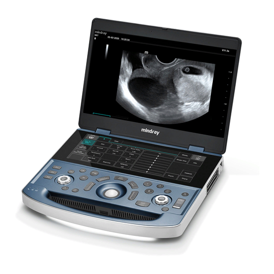
Part II General Information Product Specifications 1.1 Product Overview 1.1.1 Intended Use This product is intended for clinical ultrasound diagnostic examination. 1.1.2 System Appearance Name Description Shows the images and parameters during scanning. Touch screen Serves as a man-machine interface for operations and control. - Page 136 Part II General Information Name Description Power button/indicator Powers up or down the system. The indicator is on after the system is powered up. S-VIDEO interface S-Video signal output Network interface Connecting to the network HDMI port Outputs HD multimedia signals. USB port Connects USB devices (4 pcs).
-
Page 137: Technical Specifications
Part II General Information 1.2 Technical Specifications 1.2.1 Physical Specifications Dimensions (D × W × H): 322±5 mm × 364±5 mm × 44±3 mm Weight: < 4.0 kg (including the embedded battery) 1.2.2 Electrical Specifications Voltage: 100 V to 240 V AC ... - Page 138 Part II General Information Touch panel size: 70±1 mm (diameter) Product Specifications...
-
Page 139: Product Principle
Part II General Information Product Principle 2.1 General Structure of Hardware System Figure 2-1 Schematic diagram of the hardware system S-video IO board OLED HDMI WIFI USB3.0 *4 Main board USB2.0 POWER Clock USB3.0*4 HDMI POWER_BTN USB2.0*4 Ethernet network Convers DDR BUS ion chip Touch... -
Page 140: Main Board
Part II General Information Probe board: connecting the probe to the main unit COME module (or PC module): Doppler running platform Multifunctional board (optional): implementing the 4D&TEE&CW functions Main display module: 15.6'' display capable of sensing the brightness of ambient light. ... - Page 141 Part II General Information 2.2.1.2 PHV Power Supply Figure 2-3 Block diagram of the PHV power supply P12V 12VIN LC filter AP100V AN100V PHV1P Flyback PHV1N circuit Overcurrent/ PHV2P overvoltage PHV2N signal UART_TX UART_RX Function description: The PHV power supply provides power to the transmit circuit and has six output channels: ...
- Page 142 Part II General Information Fig 2-4 Block diagram of the backend Console board Power module TrackBall Module Battery Console_MCU LED & Drivers Touch Panel Light charge/ DC-DC OLED TCG Module Sensor discharge On/off Back-end Power Charge and System power on/off discharge status eDP/DP...
-
Page 143: Probe Board
Part II General Information Circuit Unit Function Ultrasound related Transmit/Receive control functional circuit Probe control 4D and TEE probe control (reserved function) PHV control 2.2.3 Frontend of the Main Board Figure 2-5 Block diagram of the frontend system of the main board Front-end module ATGC... -
Page 144: Tee/Cw
Part II General Information 2.4 4D/TEE/CW The multifunctional board implements the 4D/TEE/CW functions and connects to the main board through the BTB connector. Figure 2-6 Block diagram of the multifunctional board 4D_TEE_CW BOARD PHASE_A_POS Filter Network 4D_ERROR PHASE_A_NEG TPA3100D2 4D_EN PHASE_B_POS Filter Network... - Page 145 Part II General Information Board Function Description Control panel Trackball, custom function keys, backlight control, system status indicator, encoder, and buzzer Switch button board Power-on/off and cover opening detection, with partial power-on/off status indication functions Touch screen 12.3-inch LED display, working with the main display for operation control and supporting the touch function Fig 2-7 Block diagram of the control panel...
-
Page 146: Main Display Unit
Part II General Information The PSOC debugging interface and FPGA/JTAG interface on the control panel should be convenient for debugging. The control panel contains the AC status indicator, battery status indicator, and disk status indicator. Indicator details are confirmed based on UI requirements. 2.7 Main Display Unit Figure 2-8 Block diagram of the display 2.3"AMO... -
Page 147: Probe Expansion Board
ECG triggering signal is actively sent to the system controller to start scan transmission. The system can be connected to an ECG sensor, which is compatible with ports of Mindray monitors. The following figure shows the structure of the ECG module. -
Page 148: Trolley Power Supply
Part II General Information Figure 2-10 Block diagram of the ECG module ECG lead ECG Board Filterin Samp DC IN Magnify ling Socke Main Board t Port Serial port Heart rate test 2.10 Trolley Power Supply The trolley power supply is used to power the main unit system. When AC input is available, the main unit system is powered by AC_DC power. - Page 149 Part II General Information 2.10.1 Protection and Indicator Board The protection and indicator board implements the following functions: Converting AC input and providing an AC status indicator. Assisting in output control. Specifically, assist in output connection after the main unit is started and in output disconnection after the main unit stands by or shut down.
- Page 150 Part II General Information Figure 2-13 Block diagram of the trolley battery management board Current detecti on Vout Battery DC input current sett ing Battery output feedback output enabled enabled DC input current sett ing MOS switch Voltage INA194 MOS switch BQ24610 LTC3789 adjustment...
- Page 151 Part II General Information 2.10.4.2 Key and Indicator Board The key and indicator board is used to indicate the battery level and control the fan of the battery package. 2.10.4.3 Battery Magnetic Connection Board The battery magnetic connection board connects to the magnetic interface of the main unit to power the main unit.
-
Page 152: Power-Up Process Of The Main Unit
Part II General Information If AC power is disconnected in the shutdown state, the power management FPGA will turn off 5VSTB output and retains only 3.3VSTB if a battery is present. The system is powered up only after you press the power button. If AC power is disconnected in the standby state, the battery, if available, provides 5VSTB ... - Page 153 OS loadi ng is complete No dis play on the L CD loading i s compl ete loading i s compl ete Logo (MINDRAY) di splayed on the LCD The display resoluti on is final ly determined No dis play on the L CD...
-
Page 154: Probe And Needle-Guided Bracket
Part II General Information Probe and Needle-guided Bracket 3.1 Probe Image Model Info Remarks Probe Type Convex Applicable Needle-guided NGB-022, A: Bracket LPUBKG60 120-018879-00 C5-1s Ultrasonic Transducer(Ukraine) C5-1s 120-018876-00 C5-1s Ultrasonic Probe(FDA) 120-018877-00 C5-1s Ultrasonic Probe(CE) 120-018878-00 C5-1s Ultrasonic Probe(CFDA) Probe Type Convex Unreleased... - Page 155 Part II General Information Image Model Info Remarks 120-018934-00 C6-2s Ultrasonic Probe(Vet/CE) 120-018936-00 C6-2s Ultrasonic Probe(Vet/FDA) 120-018935-00 C6-2s Ultrasonic Probe(Vet/CFDA) Probe Type Convex Applicable Needle-guided NGB-022, A: Bracket LPUBKG60 120-018838-00 SC5-1Ns Ultrasonic Transducer (CFDA) SC5-1Ns 120-018839-00 SC5-1Ns Ultrasonic Transducer (FDA) 120-018840-00 SC5-1Ns Ultrasonic Transducer (Ukraine) 120-018841-00...
- Page 156 Part II General Information Image Model Info Remarks 120-018845-00 V11-3Hs Ultrasonic Probe(CFDA) Probe Type Linear Applicable Needle-guided Bracket 120-007605-00 L11-3VNs Ultrasonic Probe(China) L11- 120-007606-00 L11-3VNs Ultrasonic Probe(Turkey) 3VNs 120-007607-00 L11-3VNs Ultrasonic Probe(Ukraine) 120-007608-00 L11-3VNs Ultrasonic Probe(made in China) 120-007609-00 L11-3VNs Ultrasonic Probe(FDA) 120-007610-00 L11-3VNs Ultrasonic Probe(CE) Probe Type...
- Page 157 Part II General Information Image Model Info Remarks 120-018939-00 L13-3s Ultrasonic Probe(Vet/FDA) 120-018940-00 L13-3s Ultrasonic Probe (CFDA) 120-018941-00 L13-3s Ultrasonic Probe (CE) 120-018942-00 L13-3s Ultrasonic Probe(FDA) 120-018943-00 L13-3s Ultrasonic Probe(Ukraine) Probe Type Linear Applicable Needle-guided NGB-053 Bracket 120-018834-00 L13-3Ns Ultrasonic Transducer (CFDA) L13-3Ns 120-018835-00 L13-3Ns Ultrasonic Transducer (FDA)
- Page 158 Part II General Information Image Model Info Remarks 120-018858-00 L20-5s Ultrasonic Probe(CE) 120-018859-00 L20-5s Ultrasonic Probe(CFDA) 120-018860-00 L20-5s Ultrasonic Probe(Ukraine) Probe Type Phased array Applicable Needle-guided NGB-011 Bracket 120-018872-00 P4-2s Ultrasonic Probe(FDA) P4-2s 120-018873-00 P4-2s Ultrasonic Probe(CE) 120-018874-00 P4-2s Ultrasonic Probe(CFDA) 120-018875-00 P4-2s Ultrasonic Transducer(Ukraine) Probe Type...
- Page 159 Part II General Information Image Model Info Remarks Applicable Needle-guided NGB-011 Bracket 120-013737-00 SP5-1Ns Ultrasonic Probe(FDA) 120-013738-00 SP5-1Ns Ultrasonic Probe(CFDA) 120-013739-00 SP5-1Ns Ultrasonic Probe(CE) 120-013740-00 SP5-1Ns Ultrasonic Probe(Ukraine) Probe Type Convex Applicable Needle-guided NGB-015 Bracket 120-021901-00 C5-2s Ultrasonic Probe(FDA) C5-2s 120-021902-00 C5-2s Ultrasonic Probe(CFDA) 120-021900-00...
-
Page 160: Needle-Guided Brackets
Part II General Information 3.2 Needle-guided Brackets Image Model Info Remarks Metal/needle Type undetachable Biopsy Angle/Depth Applicable Biopsy Needle 16G, 17G, and 18G 115-001751-00 NGB-004 Needle-guided Bracket 115-002283-00 NGB-004 Needle-guided Bracket 120-001450-00 NGB-004 Needle-guided Bracket/VET NGB-004 120-001451-00 NGB-004 Needle-guided Bracket/VET 120-001452-00 NGB-004 Needle-guided Bracket/VET 120-005078-00... - Page 161 Part II General Information Image Model Info Remarks Metal: 0022-30-32953 NGB-006 NEEDLE GUIDE BRACKET 0022-30-32954 NGB-006 Needle-guided Bracket/STEEL 0022-30-32955 NGB-006 Needle-guided Bracket/STEEL Plastic: PN(Metal) 115-001755-00 NGB-006 Needle-guided Bracket/STEEL NGB-006 Needle-guided 120-002151-00 Bracket/STEEL/VET NGB-006 Needle-guided 120-002152-00 Bracket/STEEL/VET NGB-006 Needle-guided 120-002153-00 Bracket/STEEL/VET Probe and Needle-guided Bracket...
- Page 162 Part II General Information Image Model Info Remarks 120-005920-00 NGB-006 Needle-guided Bracket 0022-30-90733 NGB-006 Needle-guided Bracket/PLAS 0022-30-90735 NGB-006 Needle-guided Bracket/PLAS 0022-30-91106 NGB-006 Needle-guided Bracket/PLAS 115-001754-00 NGB-006 Needle-guided Bracket/PLAS P/N(Plastic) NGB-006 Needle-guided 120-002154-00 Bracket/PLAS/VET NGB-006 Needle-guided 120-002155-00 Bracket/PLAS/VET NGB-006 Needle-guided 120-002156-00 Bracket/PLAS/VET 120-005921-00 NGB-006 Needle-guided Bracket...
- Page 163 Part II General Information Image Model Info Remarks Metal: Metal: 14G, 16G, 18G, 20G, 22G Applicable Biopsy Needle Plastic: 13G, 15G, 16G, 18G, 20G 0022-30-33012 NGB-007 NEEDLE GUIDE BRACKET 0022-30-33013 NGB-007 Needle-guided Bracket/STEEL 0022-30-33014 NGB-007 Needle-guided Bracket/STEEL Plastic: 115-001757-00 NGB-007 Needle-guided Bracket/STEEL 120-001179-00 NGB-007 Needle-guided Bracket/VET PN(Metal)
- Page 164 Part II General Information Image Model Info Remarks 0022-30-90739 NGB-007 Needle-guided Bracket/PLAS 0022-30-91107 NGB-007 Needle-guided Bracket/PLAS 115-001756-00 NGB-007 Needle-guided Bracket/PLAS 120-001176-00 NGB-007 Needle-guided Bracket/VET 120-001177-00 NGB-007 Needle-guided Bracket/VET 120-001178-00 NGB-007 Needle-guided Bracket/VET 120-005081-00 NGB-007 Needle-guided Bracket 120-005540-00 NGB-007 Needle-guided Bracket Type Metal/needle detachable NGB-010...
- Page 165 Part II General Information Image Model Info Remarks 13G, 15G, 16G, 18G, and Applicable Biopsy Needle 0022-30-90749 NGB-010 Needle-guided Bracket 0022-30-90751 NGB-010 Needle-guided Bracket 0022-30-91110 NGB-010 Needle-guided Bracket 115-001761-00 NGB-010 Needle-guided Bracket 120-001891-00 NGB-010 Needle-guided Bracket/VET 120-001892-00 NGB-010 Needle-guided Bracket/VET 120-001893-00 NGB-010 Needle-guided Bracket/VET 120-011970-00...
- Page 166 Part II General Information Image Model Info Remarks 0022-30-90753 NGB-011 Needle-guided Bracket 0022-30-90755 NGB-011 Needle-guided Bracket 115-001762-00 NGB-011 Needle-guided Bracket 120-001182-00 NGB-011 Needle-guided Bracket/VET 120-001183-00 NGB-011 Needle-guided Bracket/VET 120-001184-00 NGB-011 Needle-guided Bracket/VET 120-005133-00 NGB-011 Needle-guided Bracket 120-005537-00 NGB-011 Needle-guided Bracket Type Metal/needle detachable NGB-015...
- Page 167 Part II General Information Image Model Info Remarks 14G, 16G, 18G, 20G, and Applicable Biopsy Needle 115-002796-00 NGB-015 Needle-guided Bracket 115-002797-00 NGB-015 Needle-guided Bracket 115-003835-00 NGB-015 Needle-guided Bracket 120-001185-00 NGB-015 Needle-guided Bracket/VET 120-001186-00 NGB-015 Needle-guided Bracket/VET 120-001187-00 NGB-015 Needle-guided Bracket/VET 120-005134-00 NGB-015 Needle-guided Bracket Type...
- Page 168 Part II General Information Image Model Info Remarks 14G, 16G, 18G, 20G, and Applicable Biopsy Needle 120-002051-00 NGB-018 Needle-guided Bracket 120-002052-00 NGB-018 Needle-guided Bracket 120-002053-00 NGB-018 Needle-guided Bracket 120-002054-00 NGB-018 Needle-guided Bracket/VET 120-002055-00 NGB-018 Needle-guided Bracket/VET 120-002056-00 NGB-018 Needle-guided Bracket/VET 120-005135-00 NGB-018 Needle-guided Bracket 120-005538-00...
- Page 169 Part II General Information Image Model Info Remarks 14G, 16G, 18G, 20G, and Applicable Biopsy Needle 120-002903-00 NGB-022 Needle-guided Bracket 120-002904-00 NGB-022 Needle-guided Bracket 120-002905-00 NGB-022 Needle-guided Bracket 120-002906-00 NGB-022 Needle-guided Bracket/VET 120-002907-00 NGB-022 Needle-guided Bracket/VET 120-002908-00 NGB-022 Needle-guided Bracket/VET 120-005138-00 NGB-022 Needle-guided Bracket 120-005539-00...
- Page 170 Part II General Information Image Model Info Remarks 120-003556-00 NGB-024 Needle-guided Bracket 120-003557-00 NGB-024 Needle-guided Bracket 120-003558-00 NGB-024 Needle-guided Bracket 120-003559-00 NGB-024 Needle-guided Bracket/VET 120-003560-00 NGB-024 Needle-guided Bracket/VET 120-003561-00 NGB-024 Needle-guided Bracket/VET 120-011974-00 NGB-024 Needle-guided Bracket Type Metal/needle detachable Biopsy Angle/Depth 1.6°...
- Page 171 Part II General Information Image Model Info Remarks 120-003667-00 NGB-025 Needle-guided Bracket/VET 120-003668-00 NGB-025 Needle-guided Bracket/VET 120-003669-00 NGB-025 Needle-guided Bracket/VET 120-005140-00 NGB-025 Needle-guided Bracket Type Metal/needle detachable Biopsy Angle/Depth 40°, 50°, and 60° 14G, 16G, 18G, 20G, and Applicable Biopsy Needle 120-004403-00 NGB-034 Needle-guided Bracket NGB-034...
- Page 172 Part II General Information Image Model Info Remarks 120-004408-00 NGB-034 Needle-guided Bracket/VET 120-005142-00 NGB-034 Needle-guided Bracket Type Metal/needle detachable Biopsy Angle/Depth 7°, 25°, and 35° 14G, 16G, 18G, 20G, and Applicable Biopsy Needle 120-004740-00 NGB-036 Needle-guided Bracket NGB-036 120-004741-00 NGB-036 Needle-guided Bracket 120-004742-00 NGB-036 Needle-guided Bracket 120-004743-00...
- Page 173 Part II General Information Image Model Info Remarks Applicable Biopsy Needle 20G, 21G, 22G, and 23G 120-011952-00 NGB-043 Needle-guided Bracket 120-011953-00 NGB-043 Needle-guided Bracket 120-011954-00 NGB-043 Needle-guided Bracket 120-011955-00 NGB-043 Needle-guided Bracket 120-011956-00 NGB-043 Needle-guided Bracket 120-011957-00 NGB-043 Needle-guided Bracket 120-011958-00 NGB-043 Needle-guided Bracket Type...
- Page 174 Part II General Information Image Model Info Remarks 120-011961-00 NGB-044 Needle-guided Bracket 120-011962-00 NGB-044 Needle-guided Bracket 120-011963-00 NGB-044 Needle-guided Bracket 120-011964-00 NGB-044 Needle-guided Bracket 120-011965-00 NGB-044 Needle-guided Bracket 120-011966-00 NGB-044 Needle-guided Bracket Metal/needle Type undetachable Biopsy Angle/Depth 1° NGB-045 Applicable Biopsy Needle 16G, 17G, and 18G 120-013102-00 NGB-045 Needle-guided Bracket...
- Page 175 Part II General Information Image Model Info Remarks 120-013103-00 NGB-045 Needle-guided Bracket 120-013104-00 NGB-045 Needle-guided Bracket 120-013105-00 NGB-045 Needle-guided Bracket 120-013106-00 NGB-045 Needle-guided Bracket 120-013107-00 NGB-045 Needle-guided Bracket 120-013108-00 NGB-045 Needle-guided Bracket Type Metal/needle detachable Biopsy Angle/Depth 40°, 50°, and 60° Applicable Biopsy Needle 11G to 23G NGB-053...
- Page 176 Part II General Information Image Model Info Remarks 120-013602-00 120-013603-00 120-013604-00 Probe and Needle-guided Bracket...
-
Page 177: Field Replaceable Unit
Part II General Information Field Replaceable Unit This chapter lists the details of the Field Replaceable Units (FRU) of the system. Please refer to the explosive view and the FRU table below. Level 0 represent the main Assembly of the system, and the whole system is divided into 6 Assembly. ... -
Page 178: Explosive View
Part II General Information 4.1 Explosive View Field Replaceable Unit... -
Page 179: Assembly Explosive View
Part II General Information 4.2 Assembly Explosive View 4.2.1 Monitor Assembly (A0) Order Number Part Name Qty. Remark 115-067739-00 LCD Assembly( Gray/FRU) Include Wi-Fi and 4G module antenna 115-067740-00 LCD Assembly(Blue/FRU) Include Wi-Fi and 4G module antenna Field Replaceable Unit... - Page 180 Part II General Information 4.2.2 Control Panel Assembly (B0) Field Replaceable Unit...
- Page 181 043-011001-00 Kit, Encoder Knob(POC Model) With the power button and the 115-067743-00 Power Button Assembly(With cable/FRU) connecting cable 115-067744-00 Trackball Assembly(FRU) For MX7 or MX8 115-068060-00 Touch Pad(POC/FRU) Only for ME series 049-001657-00 Silicon Overlay(FRU) 115-067853-00 Control Panel PCBA(FRU) Only the control panel PCBA...
- Page 182 Encoder Knob and Key, touch Control Board 115-069355-00 Touch screen Assembly(POC model/FRU) Only include touch screen 115-069368-00 POC Control Panel Cover( Blue) Use for MX7 POC model 115-069360-00 POC Control Panel Cover( Gray) Use for MX8 POC model Field Replaceable Unit...
- Page 183 Part II General Information 4.2.3 Main Unit Assembly (C0) Field Replaceable Unit...
- Page 184 Part II General Information Order Number Part Name Qty. Remark 115-067746-00 Fans Assembly(FRU) 115-067852-00 PC Module(FRU) 115-068057-00 Magnetic Power Socket(FRU) 115-068058-00 S-video Interface Board(FRU) Two choice one before 115-067776-00 SSD(FRU) shipment Two choice one before 115-068056-00 HDD(FRU) shipment 115-067748-00 Optional, not yet released Kit, 4G Module 115-067749-00 Wi-Fi Module...
- Page 185 Part II General Information 4.2.4 Cable and Accessories (D0) D1-D6 Order Number Part Name Qty. Remark 009--003704-00 Adapter power cord( China,2.5M) 009-003703-00 Adapter power cord( Europe,2.5M) 009-003701-00 Adapter power cord( U.K,2.5M) 009-005417-00 Brazil Adapter power cord( 3.5M) 009-003702-00 Adapter power cord( USA,2.5M) 009-004941-00 Adapter power cord(Australian ,2.5M) 115-068076-00...
- Page 186 Part II General Information 4.2.5 MT3 Mobile Trolley (E0) Field Replaceable Unit...
- Page 187 Part II General Information Order Number Part Name Qty. Remark 115-067876-00 Probe Extender Cover(FRU) 115-068431-00 Probe Extender (No Pen Probe Port/FRU) 115-067873-00 Gas Spring Assembly(FRU) 115-067874-00 Left Probe Holder Assembly(FRU) 043-012047-00 Adapter Basket(FRU) 115-067867-00 Retractable AC Cable Assembly (China) 115-067868-00 Retractable AC Cable Assembly (Europe) 115-067869-00 Retractable AC Cable Assembly (America)
- Page 188 Part II General Information Order Number Part Name Qty. Remark 115-068065-00 Trolley Control panel Top Cover(FRU) 115-067875-00 Right Probe Holder Assembly(FRU) 115-068061-00 Mobile Trolley Handle Upper Cover(FRU) 115-068064-00 Mobile Trolley Handle Front Cover(FRU) 043-010856-00 Small Tray(FRU) 043-012046-00 Big Basket(FRU) 115-067866-00 Caster(FRU) 051-003668-00 2146 Fuse and LED Board PCBA...
- Page 189 Part II General Information 4.2.6 MT3 Mobile Trolley Cable (F0) Order Number Part Name Qty. Remark 009-009403-00 Power Supply Spring Cable(FRU) 115-068066-00 DC Input Cable With Magnetic connector(FRU) 115-068079-00 Power cable to Battery Pack (FRU) 115-068080-00 Battery Pack Output Cable(FRU) Field Replaceable Unit...
- Page 190 Part II General Information Order Number Part Name Qty. Remark For upgrading the pen probe function, used with the probe 009-000356-00 Pen Probe Line (M7) extender , 4D/TEE/CW board and pen probe 4.2.7 MT2 Mobile Trolley (G0) Field Replaceable Unit...
- Page 191 Part II General Information Order Number Part Name Qty. Remark 115-070488-00 Bin(FRU) Only used for MT2 trolley 115-070487-00 UMT-170 Trolley Caster and Spanner(FRU) Only used for MT2 trolley 115-073566-00 MT2 Printer brackets Only used for MT2 trolley Optional, including installation 115-058832-00 Probe Extender (FRU/MT2) bracket and extender...
-
Page 192: Structure And Assembly/Disassembly
Part II General Information Structure and Assembly/Disassembly 5.1 System Structure 5.1.1 Main Unit Explosive view of the main unit Figure 5-1 Name Name Equipment body Spindle cover Dustproof Net Control panel Li-ion battery Control Panel to Main Board Battery Chamber Cover Connecting Cable SSD cover plate Structure and Assembly/Disassembly... -
Page 193: Assembly/Disassembly Of The Main Unit
Part II General Information 5.1.2 Trolley Figure 5-2Explosive view of the trolley Name Name Protective Bracket Mobile Trolley Output Control Board( Trolley Control panel Top Cover Retractor Right Probe Holder Assembly Adapter Basket Mobile Trolley Handle Upper Cover Power adapter (applicable to the main unit, absent for the trolley) Mobile Trolley Handle Front Cover Left Probe Holder Assembly... - Page 194 N-206S 095-000077-00 ESD gloves: 1 pair 5.2.1.2 Personnel Requirement Only technical professionals from Mindray or engineers authorized by Mindray after training can perform maintenance and check. 5.2.1.3 Disassembly Requirements Make the following preparations before disassembling the ultrasound equipment. Stop scanning and image capture, shut down the system, disconnect the AC power supply, and remove the AC power cable.
- Page 195 Part II General Information Battery compartment cover M3X8 Nylok screw Pull the battery pull tab and take out the battery. Battery Battery pull tab 5.2.3 SSD Card Remove the M2.5X4 plus flat-head screws from the SSD cover plate, and then take off the SSD cover plate.
- Page 196 Part II General Information Antenna buckle Remove the LCD signal cable with the black pull tab. LCD signal cable Remove the button battery. Insert a flathead screwdriver into the gap between the button battery and the plastic cover. The button battery ejects automatically. Button battery Remove the SSD card, 4G card, and Wi-Fi card.
- Page 197 Part II General Information M3X5 cross recessed flathead screw 5.2.4 LCD and Keyboard Cover Remove the spindle cover. Insert a flathead screwdriver into the gap between the edge of the spindle cover and the keyboard cover, and pull out the spindle cover. Spindle cover Detach the LCD.
- Page 198 Part II General Information LCD signal cable Remove the screws fixing the bottom case to the keyboard cover. Use a crosshead screwdriver to remove the 10 M3X8 Nylok screws on the bottom case. M3X8 Nylok screw Remove the FPC flat cable between the main board and the control panel. Lift the keyboard cover softly.
- Page 199 Part II General Information FPC flat cable between the main board and the control panel 5.2.5 Equipment body Speaker Put the detached equipment body on a table and remove the speaker cable to detach the speaker. Speaker cable 4D/TEE/CW board Use a screwdriver to remove the three M3X14 cross recessed panhead screws, and lift the 4D/TEE/CW board upwards vertically.
- Page 200 Part II General Information M3X14 cross recessed panhead 4D/TEE/CW board screw Probe board Use a screwdriver to remove the 5 M3X5 cross recessed flathead screws and lift the probe board socket upwards vertically. Probe board socket M3X5 cross recessed flathead IO shield cover Use a screwdriver to remove the two M3X5 cross recessed flathead screws and take off the IO shield cover.
- Page 201 Part II General Information IO shield cover M3X5 cross recessed flathead screw S-Video board Use a screwdriver to remove the M3X5 cross recessed flathead screw and remove the S-Video board cable. S-Video board M3X5 cross recessed flathead screw Magnetic socket Remove the magnetic socket cable to take off this component.
- Page 202 Part II General Information Magnetic socket cable PC module radiator Use a screwdriver to remove the four M2.5X8 cross recessed panhead screws and lift the PC module radiator upwards vertically. M2.5X8 cross recessed panhead screw FPGA module radiator Use a screwdriver to remove the four M2.5X4 plus flat-head screws. The FPGA contact surface is coated with thermally conductive silicon and therefore is adhesive.
- Page 203 Part II General Information M2.5X4 plus flat-head screw Main board PCBA Remove the fan cable bundle from the interface. Fan cable bundle interface Use a screwdriver to remove the nine M3X5 cross recessed flathead screws and take off the main board PCBA. Structure and Assembly/Disassembly...
- Page 204 Part II General Information M3X5 cross recessed flathead screw 10. Hard disk drive Use a screwdriver to remove the M3X5 cross recessed flathead screw and take off the hard disk drive. M3X5 cross recessed flathead screw 11. Fan Use a screwdriver to remove the M3X5 cross recessed flathead screw and take off the cable crimp.
- Page 205 Part II General Information Cable crimp M3X5 cross recessed flathead screw b. Pull out the five fans upwards vertically one by one. 5.2.6 Dust Filter Remove the two dust filters with a flathead screwdriver. Dust filter 5.2.7 Control Panel (Non POC model) Remove the control panel.
- Page 206 Part II General Information FPC flat cable between the main board and the control panel Cable between the control panel and the touch screen Open the cable crimps and take off the two cables connected between the control panel and the touch screen.
- Page 207 Part II General Information Power keypad Power button cable Trackball Use a screwdriver to remove the two M3X5 cross recessed flathead screws and pull out the trackball cable from the interface downwards horizontally. Structure and Assembly/Disassembly...
- Page 208 Part II General Information M3X5 cross recessed flathead screw Trackball cable Rotary encoder button Pull out the two rotary encoder buttons. Rotary encoder button Control panel PCBA Use a screwdriver to remove the 14 M2.5X4 plus flat-head screws and take off the control panel PCBA.
- Page 209 Part II General Information M2.5X4 plus flat-head screw Silicon keyboard The silicon keyboard needs to be manually detached as the silicon columns of the silicon keyboard are embedded into the control panel. Silicon keyboard Take off the keys on the keyboard cover. Structure and Assembly/Disassembly...
- Page 210 Part II General Information 5.2.8 Control Panel (POC model) Remove the control panel. Refer to step 3 to 4 in 5.2.4. Control panel cable Remove the FPC flat cable between the main board and the control panel upwards vertically from the interface on the control panel.
- Page 211 Part II General Information Cable crimp Cable between the control panel d the touch screen Power button Pull out the power keypad and remove the power button cable from the interface. Power keypad Power button cable Trackpad Structure and Assembly/Disassembly...
- Page 212 Part II General Information Use a screwdriver to remove the two M3X5 cross recessed flathead screws and pull out the touch control board cable from the interface downwards horizontally. Touch control board M3X5 cross recessed flathead screw Rotary encoder button Pull out the two rotary encoder buttons.
- Page 213 Part II General Information M2.5X4 plus flat-head screw Silicon keyboard The silicon keyboard needs to be manually detached as the silicon columns of the silicon keyboard are embedded into the control panel. Silicon keyboard Take off the keys on the keyboard cover. Structure and Assembly/Disassembly...
- Page 214 Part II General Information 10. POC control panel upper cover Use a screwdriver to remove the 6 M3X5 plus flat-head screws and take off the POC control panel upper cover from the bottom side. Structure and Assembly/Disassembly...
-
Page 215: Disassembling The Trolley
Part II General Information M3X5 plus flat-head screws 5.3 Disassembling the Trolley 5.3.1 Preparations 5.3.1.1 Tools Required Name Type Remarks Crosshead screwdriver 107 × 75 Crosshead screwdriver 107 × 75 0000-10-10884 M4 and M5 Flathead screwdriver Inner hexagon spanner 369H (1.5–6.0 mm) 095-000062-00 M5 and M4 Cable cutter... - Page 216 Type Remarks Caster wrench 5.3.1.2 Personnel Requirement Only technical professionals from Mindray or engineers authorized by Mindray after training can perform maintenance and check. 5.3.1.3 Disassembly Requirements Make the following preparations before disassembling the ultrasound equipment. Stop scanning and image capture, shut down the system, disconnect the AC power supply, and remove the AC power cable.
- Page 217 Part II General Information M2.5X4 cross recessed flathead screw (3 pcs) Probe eject lever (3 pcs) At the notch shown in the following figure, use a flathead screwdriver to force open the extender cover plate according to the direction indicated in the figure. Notch Flathead screwdriver...
- Page 218 Part II General Information M4X12 cross recessed panhead screw (2 pcs) Extender 5.3.4 Removing the Probe Holder The trolley has two holders: left holder and right holder. Remove the three M3X12 cross recessed countersunk head screws and two M4X12 cross recessed countersunk head screws from the beneath of the trolley panel, and then take off the holders from the trolley panel.
- Page 219 Part II General Information 5.3.5 Removing the Anti-Collision Bracket The trolley has two anti-collision brackets mounted on the left and right sides of the trolley panel. Use an Allen wrench (M5) to remove the 10 M5X12 hex socket screws for fastening the anti-collision brackets on the left and right sides of the trolley panel, and then take off the anti-collision brackets from the panel.
- Page 220 Part II General Information Upper cover of the control panel M4X12 cross recessed countersunk head screw (10 pcs) 5.3.7 Removing the Upper Cover of the Trolley Handle Remove the upper cover of the control panel. For details, see 5.3.6. Use an M3 crosshead screwdriver to remove the four M3X5 flathead screws from the rear side of the handle, as shown in the following figure.
- Page 221 Part II General Information Remove the guy-wire on the control panel side. Remove the cable clip. Remove the M4X12 cross recessed panhead screw for fastening the cable clip and take off the cable clip. Cable clip (fastened using an M4X12 cross recessed panhead screw) Remove the guy-wire fixing block.
- Page 222 Part II General Information Guy-wire anchor Connecting rod Take out the guy-wire nut and bolt from the guy-wire fixing block. Remove the guy-wire nut and bolt from the fixing block with your hands. Guy-wire bolt Guy-wire nut Remove the panel. Use an M5 Allen wrench to remove the six M5X16 hex socket screws shown in the following figure.
- Page 223 Part II General Information M5X16 hex socket screw (6 pcs) 5.3.9 Disassembling the Gas Spring Remove the control panel. For details, see 5.3.8. Remove the shell of the outer column. Use an Allen wrench to remove the six M4X8 hex half-round head screws on the shell of the outer column.
- Page 224 Part II General Information Front side (handle side) Shell of the outer column M4X8 hex half-round head screw (6 pcs) Remove the four M3X8 cross recessed panhead screws on the rear side of the shell of the outer column. Then hold the shell of the outer column and let it fall down to the bottom of the outer column.
- Page 225 Part II General Information Remove the extender brackets. As shown in the following figure, first remove the two M3X8 cross recessed panhead screws on the left side of the column for fastening the left extender bracket, and then push the left extender bracket rightwards to take off it.
- Page 226 Part II General Information Spring cable Right extender bracket Cable tie M3X8 cross recessed panhead screw Remove the shell of the outer column. Take off the shell of the outer column from bottom up. Drag the spring cable upwards to avoid clamping the cable.
- Page 227 Part II General Information On top of the column front, remove the four M3X12 cross recessed panhead screws for fastening the assembly bracket of the shell, and take off the assembly bracket. M4X12 cross recessed panhead screw (4 pcs) Assembly bracket of the shell Remove the shell of the inner column.
- Page 228 Part II General Information M4X12 cross recessed panhead screw (1 pcs) Cable clip Remove the upper positioning plate of the gas spring. On the side of the gas spring at the top of the column, remove the two M3X8 cross recessed panhead screws for fastening the upper positioning plate of the gas spring, and then take out the upper positioning plate.
- Page 229 Part II General Information Lower positioning plate M3X8 cross recessed panhead Upper cover of screw (1 pcs) the base Remove the upper gas spring pin. Pull the guy-wire to press down the gas spring and ensure that the gas spring is lower than the highest point by 10–20 cm.
- Page 230 Part II General Information Use a flathead screwdriver to pry the pin part exceeding the fixing block from the tail of the pin, until the tail of the pin totally enters into the right hole on the fixing block. At this time, a slot appears at the pin head.
- Page 231 Part II General Information Outer column Gas spring 5.3.10 Disassembling the Winder Tear off the screw paster from the shell of the column and remove the two M5X10 cross recessed countersunk head screws. M5X10 cross recessed countersunk head screw (2 pcs) Screw paster Remove the base.
- Page 232 Part II General Information M4X12 cross recessed panhead screw (8 pcs) Take off the base from the trolley and remove the M4X12 cross recessed screws for fixing the adapter bracket and magnetic ring. Base M4X12 cross recessed panhead screw Adapter bracket Magnetic ring Remove the winder.
- Page 233 Part II General Information M4X12 cross recessed panhead screw (4 pcs) 5.3.11 Protection and Indicator Board and Output Control Board Remove the protection and indicator board. Wear a pair of ESD gloves, remove the two plugs from the board shown in the figure, remove the two M3X8 cross recessed panhead screws for fastening the board, and take off the protection and indicator board.
- Page 234 Part II General Information Protection and indicator board 2-pin plug 4-pin plug M3X8 cross recessed panhead screw (2 pcs) Remove the output control board. Remove the 2-pin plug from the board, and then the two interconnection cable terminals (8-pin and 10-pin).
- Page 235 Part II General Information Custom Allen wrench Caster Base Structure and Assembly/Disassembly...
-
Page 236: Function And Performance Check
Part II General Information Function and Performance Check 6.1 Description This chapter describes how to check major functions and performance of the product. The check methods are only for reference and do not need to be performed on a regular basis. 6.2 Checking System Status 6.2.1 Operating Status The ultrasound equipment is started and shut down properly (startup and shutdown time within the... -
Page 237: General Check
Part II General Information 6.3 General Check 6.3.1 Check Flow Check the control panel Check the monitor Check peripherals Check ECG Check I/O port 6.3.2 Check Items 6.3.2.1 Control Panel Procedure Acceptance Criteria 1. Check the buttons, keys and knobs. All keys and knobs are effective. - Page 238 Part II General Information Procedure Acceptance Criteria Perform display maintenance. Click the function buttons to perform the test and the display responds properly. The defective pixel Log in to the system as user Service. detection criteria are as follows: Choose Setup > Maintenance > Setup > Test Main Monitor.
-
Page 239: Function Check
Part II General Information 6.3.2.4 ECG Function Procedure Acceptance Criteria Perform the following check after ECG is activated. ECG waveforms and a heart mark are confirming that the system is equipped displayed, and the respiratory waveform is displayed on with the ECG module: the upper right of the screen. - Page 240 Part II General Information 6.4.1 Check Flow Check image mode Check basic measurement Check cine mode Check probe usage Image and imaging management Record and save the check 6.4.2 Check Items 6.4.2.1 Imaging Mode B Mode In B mode scan, the image parameter area on the screen displays the real-time parameter values as follows: Echo Item...
- Page 241 Part II General Information Control panel Procedure Acceptance Criteria Press the B parameter The system enters the B mode and the B-mode screen appears. button. Gain control G The gain is increased when the knob is turned clockwise. Turn the Gain knob. The gain is decreased when the knob is turned anticlockwise.
- Page 242 Part II General Information Procedure Acceptance Criteria iClear Press Set or the parameter button for adjustment. Touch screen >iClear The system provides 5 levels of iClear effects adjustment, off represents no iClear is turned on, and the bigger the value the stronger the effect. Touch screen >...
- Page 243 Part II General Information Adjustment Items Control panel Gain, Depth, and iTouch Touch screen Image Quality, Line Density, Persistence, Smooth, Sensitivity, B/C Wide, Velocity Tag, Flow State, WF, Invert, Dual Live, Scale, Tint Map, Priority, Baseline, Map, PW Steer, and TGC Power mode ...
- Page 244 Part II General Information 6.4.2.3 Cine Review Procedure Acceptance Criteria Press Freeze to freeze the image, and The system enters the cine review state. the system enters the manual review The system enters the auto review state. state automatically. (Prerequisite: Set Status after Freeze to Cine.) Tap iStation on the touch screen and ...
- Page 245 Part II General Information 6.4.2.4 Probe Identification and Switching Procedure Acceptance Criteria Press Freeze and insert the probe. Press Freeze The ultrasound equipment can identify the and tap Probe on the touch screen. connected probe properly. Press Freeze, remove the probe, and insert The ultrasound equipment can immediately identify another probe.
-
Page 246: Performance Test
Part II General Information 6.5 Performance Test 6.5.1 Test Procedure Check resolution Check detection depth Check geometric positioning accuracy Blind area test Record the imaging 6.5.2 Test content The following figure is only used for reference in the testing, and the actual image effect Note: depends on the specific system. - Page 247 Part II General Information Test procedure: Place the probe head gently on the acoustic window of the phantom which is covered by water or medical ultrasonic couplant, and make sure the transverse resolution targets are displayed in the center of the image. Focus to the transverse resolution target group.
- Page 248 Part II General Information 6.5.2.3 Maximum detection depth Note: An overlarge gain may result in large noise and submergence of the echo signal. For linear array probe, the probe surface should be perfectly fit with the acoustic window on the phantom without any inclination during scan. For convex and phased probe, make sure the axial target group is placed in the central ...
- Page 249 Part II General Information 6.5.2.4 Axial Geometric Positioning Accuracy Measuring cursor should be placed on the top edge of the target image, not in the middle Note: or bottom edge. Scanning plane should be perpendicular to each target line, in other words, scanning ...
- Page 250 Part II General Information Image effect is show in the figure below: 6.5.2.5 Lateral Geometric Positioning Accuracy Note: For linear array probes, the lateral interval can be read section by section. For convex array probes, all lateral targets mus be displayed at a time. ...
- Page 251 Part II General Information Image effect is show in the figure below: 6.5.2.6 Blind area For linear array probes, the probe surface should be perfectly fit with the acoustic Note: window on the phantom without any inclination. For convex array probes, the targets in the blind area to be observed must be on the ...
- Page 252 Part II General Information Function and Performance Check...
-
Page 253: Part Iii Appendix
Part III Appendix... -
Page 254: Electrical Connection Diagram
Part III Appendix Electrical Connection Diagram Figure 1-1 Internal connections of the main unit and trolley Antenn Antenna 024-001112-00 LCD Monitor Optical sensor Secondary 15.6inch Touch Panel board screen 12.3inch 021-000458-00 021-000457-00 4G module Wi-Fi module M.2接口 051-003585-00 023-001528-00 023-001853-00 051-003512-00 024-001076-00 Trackball... -
Page 255: Description Of Self-Test Items
Part III Appendix Description of Self-Test Items 2.1 Z0101 Test of Communication Between PC Module and MF FPGA Upper-level test item None Test content Verify whether the PCIe bus between the PC module and the FPGA is normal. Test failure analysis ... -
Page 256: Z0201 Ddr Full-Space Read/Write Test
Part III Appendix Test failure analysis If the test result is NaN, the maintenance personnel end the test during the test process. If the test result is FAIL, the CPU temperature is too high. Troubleshooting suggestion First check whether the air inlets and dust filters are blocked, whether the fans are blocked, and whether the CPU radiator and heat-conducting cream are in good contact. -
Page 257: Z0202 Fpga Pressure Test
Part III Appendix If the test result is Error, restart the equipment and re-perform the self-test. If the problem persists, recover the equipment. If the test result is FAIL, replace the main board. 2.4 Z0202 FPGA Pressure Test Upper-level test item ... -
Page 258: Z0205 Power Status Test
Part III Appendix Test whether the communication serial port UART between the EC ARM nd the FPGA is normal. Read the firmware compilation time, firmware version, and boot program version. Test failure analysis If the test result is Error, the drive malfunctions. If the test result is FAIL, the serial ports of the EC ARM and the multifunctional FPGA are faulty. -
Page 259: Z0207 Network Port Test
Part III Appendix 2.9 Z0207 Network Port Test Upper-level test item None Test content The program prompts you to ensure that the network cable is connected. After connecting the network cable, the program first judges whether a wired network adapter exists and then whether the Ethernet functions properly. -
Page 260: Z0210 Program-Controlled Power Voltage Test For The Phv Module
Part III Appendix Test the UART communication between the multifunctional FPGA and the PHV Arm. Read the PHV firmware version and build version. Test failure analysis If the test result is Error, the drive malfunctions. If the test result is FAIL, the communication between the multifunctional FPGA and the PHV serial port fails. -
Page 261: Z0212 Fpga Temperature Test
Part III Appendix Troubleshooting suggestion If the test result is Error, restart the equipment and re-perform the self-test. If the problem persists, recover the equipment. If the test result is FAIL, replace the main board. 2.14 Z0212 FPGA Temperature Test Upper-level test item ... -
Page 262: Z0401 Speaker Test
Part III Appendix Set the fan speed to 50% through the UART of the SM ARM and read the current rotation speed. Then set the fan speed to 100% and read the current rotation speed to check whether the fan speed is as set. -
Page 263: Z0601 4G Module Communication Test
Part III Appendix Check whether a network adapter exists and then check whether an SSID list can be searched. Test failure analysis If the program prompts that no wireless device is detected, no wireless network adapter is identified. If the program prompts that the wireless function test fails, no Wi-Fi hotspot is detected. Troubleshooting suggestion ... -
Page 264: 0702 Function Self-Test For Keys, Encoder, And Trackball
Part III Appendix If the test result is FAIL, replace the control panel. 2.21 0702 Function Self-Test for Keys, Encoder, and Trackball Upper-level test item Control Panel USB Communication Test Test content Test whether the keys on the control panel, encoder, trackball, key backlight LED, and indication LED function properly. -
Page 265: Z0703 Key And Trackball Led Self-Test
Part III Appendix 2.22 Z0703 Key and Trackball LED Self-Test Upper-level test item Control Panel USB Communication Test Test content The program automatically checks whether the current equipment is a POC edition or bedside edition. For a bedside edition, the program automatically adjusts the brightness of the white and blue LEDs and the trackball. -
Page 266: Z0801 Parameter Board I2C Communication Test
Part III Appendix Troubleshooting suggestion If the brightness of the LEDs does not change, replace the control panel. 2.23 Z0801 Parameter Board I2C Communication Test Upper-level test item Communication Test Between PC Module and MF FPGA Test content ... -
Page 267: Z0802 Parameter Board Data Check Test
Part III Appendix Troubleshooting suggestion If the test result is Error, restart the equipment and re-perform the self-test. If the problem persists, recover the equipment. If the test result is FAIL, check whether the cable connections between the parameter board and the main unit are reliable. -
Page 268: Z0804 Backlight Control Test For The Main Display
Part III Appendix If the test result is Error, the drive malfunctions. If the test result is FAIL, brightness control for the main display is abnormal. Troubleshooting suggestion If the test result is Error, restart the equipment and re-perform the self-test. If the problem persists, recover the equipment. -
Page 269: Z0806 Optical Sensor Test
Part III Appendix The SM ARM reads the firmware version and compilation time of the secondary screen board through the UART, to check whether the communication is normal. Test failure analysis If the test result is Error, the drive malfunctions. If the test result is FAIL, the communication between the SM ARM and the secondary screen board is abnormal. -
Page 270: Z0901 Touch Screen Communication Test
Part III Appendix If the test result is FAIL, the optical sensor is faulty. Troubleshooting suggestion If the test result is Error, restart the equipment and re-perform the self-test. If the problem persists, recover the equipment. If the test result is FAIL, check whether the cables are connected reliably for the optical sensor. -
Page 271: Z0903 Backlight Control Test For The Touch Screen
Part III Appendix If the test result is Error, the drive malfunctions. If the test result is FAIL, brightness control for the touch screen is abnormal. Troubleshooting suggestion If the test result is Error, restart the equipment and re-perform the self-test. If the problem persists, recover the equipment. -
Page 272: Z10014D/Tee/Cw Board In-Position Test
Part III Appendix The program passes the test automatically if all circles turn into green. If the touch screen malfunctions during the test, click Touch Screen is Bad. Test failure analysis None Troubleshooting suggestion If the touch screen does not work at all, the touch screen driver is abnormal. In this case, reinstall the system. -
Page 273: Z1002 Tee Temperature Signal Test
Part III Appendix If the test result is NaN, reassembly the CW board. If the test result is still NaN, replace the 4D/TEE/CW board. If the problem persists, replace the main board. 2.34 Z1002 TEE Temperature Signal Test Upper-level test item ... -
Page 274: Z1101 Battery Communication Test
Part III Appendix If the test result is Error, the drive malfunctions. If the test result is FAIL, the prompted voltage does not meet the requirements. Troubleshooting suggestion If the test result is Error, restart the equipment and re-perform the self-test. If the problem persists, recover the equipment. -
Page 275: Z1202 Ecg Board Self-Test
Part III Appendix Troubleshooting suggestion If the test result is NaN, check whether the USB port malfunctions. If not, check whether the ECG driver is installed. If both check items are normal, replace the ECG board. 2.40 Z1202 ECG Board Self-Test Upper-level test item ... -
Page 276: Electrical Safety Maintenance
Part III Appendix Electrical Safety Maintenance The following electrical safety tests are considered a part of the comprehensive maintenance process and major means to detect exceptions. If the test is not performed, the patient or operator may be endangered. Perform additional tests based on the actual conditions. All tests can be performed using a commercial safety analysis tester. - Page 277 Part III Appendix Electrical safety check Equipment shell and accessories Test process Visual inspection No physical damage The switch, connector, and dashboard are free from physical damages. There are no overflowing liquid residues, such as water, Shell and accessories coffee, and chemicals.
- Page 278 Part III Appendix Electrical safety check 4-Protection ground impedance Overview Prerequisite: L1 and L2 are turned on. To measure the protection ground impedance, connect a red lead to the protection ground end, protection ground metal shell, or equipotential pole of the device under test. Press AMPERRES (soft key 3) to select the test current.
- Page 279 Part III Appendix Electrical safety check 4-Protection ground impedance Press the soft key corresponding to START TEST to apply the test current and show the impedance and current values. The test lasts about 5s. Press the print key to print the latest measurements. ...
- Page 280 Part III Appendix Electrical safety check 5-Ground leakage current test On the main panel, insert the DUT plug into the auxiliary output interface on the front panel of the 601 PRO tester when there is no power on the output end, and then turn on the DUT. Connect the applied part of the device to an available applied part terminal of the 601 PRO tester.
- Page 281 Part III Appendix Electrical safety check 5-Ground leakage current test Limit 500 μA (normal condition) IEC60601-1: 1000 μA (single fault) Electrical safety check 6-Patient leakage current test Overview The patient leakage current test aims to test the leakage current between the available applied part and the ground.
- Page 282 Part III Appendix Electrical safety check 6-Patient leakage current test On the main panel, insert the DUT plug into the auxiliary output interface on the front panel of the 601 PRO tester when there is no power on the output end, and then turn on the DUT. Connect the applied part of the device to an available applied part terminal of the 601 PRO tester.
- Page 283 Part III Appendix Electrical safety check 6-Patient leakage current test If the leakage current test on the new unit fails and the problem cannot be rectified, submit a safety failure report to prove the system problem and remove this unit. If the test fails on other units, stop using the device and notify customer service engineers to analyze or handle the problem.
- Page 284 Part III Appendix Electrical safety check 7-Patient leakage current under the condition of applied parts plus mains voltage If the calibration fails, the saved value is used until an acceptable calibration value appears. The Esc/Stop key is invalid during calibration. After the calibration is complete, the patient leakage current test under the condition of applied parts plus mains voltage appears on the screen.
- Page 285 Part III Appendix Electrical safety check 7-Patient leakage current under the condition of applied parts plus mains voltage NOTE Except the probe, if the device uses ECG or PCG, the patient leakage current should be tested. If all applied parts pertain to the same mechanical type, connect all applied parts and obtain a single measurement value.
- Page 286 Part III Appendix Electrical safety check 8-Patient auxiliary current test On the main panel, insert the DUT plug into the auxiliary output interface on the front panel of the 601 PRO tester when there is no power on the output end. Connect the patient lead to an ECG slot on the 601 PRO tester.
- Page 287 Part III Appendix Electrical safety check 8-Patient auxiliary current test Test the current output on the wall. Check that the ground is good and no cable exceptions occur. Notify the user or owner to correct related deviations. Check whether any surrounding operating power output can be used for substitution.
- Page 288 Part III Appendix NC: 500 μA Earth leakage Single fault condition ____μA current (SFC) SFC: 1000 μA Normal condition (NC) □ Limit BF____μA Patient leakage BF application type current Single fault condition □ NC: 100 μA BF____μA (SFC) SFC: 500 μA □...
-
Page 289: Phantom Usage Illustration
Phantom Usage Illustration 4.1 Ultrasound Phantom Model KS107BD A1-A5: Axial-Lateral Resolution Target String Group B: Dead Zone Target Group C: Vertical Distance Target Group D: Horizontal Distance Target Group E: Hyperechoic(tumor-like) Target F: Anechoic (Cyst-like, 10 mm in diameter) and stones-like Target G: Anechoic (Cyst-like, 6 mm in diameter) Target The detail introduction of 11 target groups is as following: 1. -
Page 290: Ultrasound Phantom Model Ks107Bg
3. C: Vertical Distance Target Group, This target group includes 19 strings, with the adjacent string interval is 10mm. 4. D: Horizontal Distance Target Group, This target group includes 7 strings, with adjacent string interval is 20mm. 5. E: Hyperechoic(tumor-like) Target, Hyperechoic target(tumor-like), is located between 70-80 mm in depth, with a 10 mm diameter cylindrical shape. - Page 291 1. A1-A4: Axial Resolution Target String Group, The top strings of each target group are at the depth of 10mm, 30mm, 50mm, 70mm. The vertical distances between adjacent strings in each target group are 3mm, 2mm, 1mm, 0.5mm respectively. The horizontal distances between adjacent are 1mm.
- Page 292 P/N: 046-019225-00 (5.0)
Need help?
Do you have a question about the MX7 and is the answer not in the manual?
Questions and answers