Table of Contents
Advertisement
Quick Links
Advertisement
Table of Contents

Related Manuals for Mindray M7Vet


Summary of Contents for Mindray M7Vet
- Page 1 M7Vet Diagnostic Ultrasound System Operation Note...
-
Page 3: Table Of Contents
Table of Contents Table of Contents ..................... i System Introduction ................1 Control Panel ................... 2 Icons on the Screens ................6 Power ON/ OFF ..................7 Enter or Search Animal Information ............8 Select Probe and Exam Mode ..............9 Image Adjustment .................. -
Page 5: System Introduction
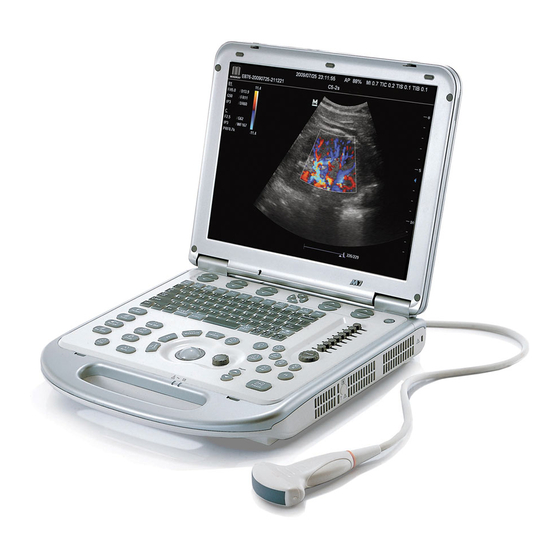
System Introduction Name Function Displays the images and parameters during Monitor scanning. Control Panel Operator-system interface or control. Probe port Connects the pencil probe Handle Used for carrying the system. Connects a probe to the main unit; or connects a Probe port probe extend module. -
Page 6: Control Panel
Control Panel <1> <2> <3> <4> <5> <6> <7> <8> <9> <10> <11> <12> <13> <14> <15> <16> <18> <17> <19> <20> <21> <22> <23> <24> <35> <25> <36> <38> <37> <26> <29> <40> <41> <30> <42> <27> <39> <28> <31>... - Page 7 different modes. <5> Soft menu Press to select the soft menu items displayed controls 5 on the bottom of the screen. Refer to the subsequent contents for specific functions. <6> Soft menu Press to select the soft menu items displayed controls 6 on the bottom of the screen.
- Page 8 status. <22> Clear Clear Press to clear the comments, measurement calipers or body marks on the screen. <23> Direction Press “Fn+/” to adjust volume or monitor keys brightness <24> iTouch Rotate to increase or decrease the image gain. Press to optimize the image, serving as a one-key optimization.
- Page 9 <45> Print Print Press to print; user-defined key. <46> Save Save Press to save; user-defined key. <47> Depth Depth Press to increase or decrease the imaging depth in scanning mode. <48> Freeze Freeze Press to freeze or unfreeze the image. <49>...
-
Page 10: Icons On The Screens
Icons on the Screens System status icons: Icons Information Free cursor Region of Interest (ROI) size or position adjustment Sample volume(SV) or M sampling line adjustment M-mark line adjustment in free Xros mode Cine Review status Measurement Status Comment status Body Mark Status Zoom status Sphere-center rotation in 3D/4D imaging mode... -
Page 11: Power On/ Off
If the system begins to function improperly – immediately stop scanning. If the system continues to function improperly – fully shut down the system and contact Mindray Customer Service Department or sales representative. If you use the system in a persistent improperly functioning state – you may harm the animal or damage the equipment. -
Page 12: Enter Or Search Animal Information
Enter or Search Animal Information To enter animal information Enter the animal information before the exam: 1. Press to end the current animal exam to start a new exam. 2. Press to enter the Animal Information screen. 3. Enter the basic information. 4. -
Page 13: Select Probe And Exam Mode
Select Probe and Exam Mode After directly connecting a probe or connecting probes via the probe extend module, you can: Select the exam mode (when only one probe is connected): (1) Press to open the exam switching dialogue box. (2) Roll the trackball and press <Set> to select the exam mode. Select the exam mode and probe (when more than one probe are connected): (1) Press to open the exam and probe switching dialog box. -
Page 14: Image Adjustment
Image Adjustment Adjustments through image menu: (1) Press or multifunctional knob to open the menu. (2) Use the trackball and or the multifunctional knob to adjust. Adjustment through soft menu controls The soft menu locates at the bottom of the screen, items of which are dependent upon image modes and preset. -
Page 15: Image Adjustment
Image Adjustment Requirement Available Operations Adjust gain Adjust TGC To modify the brightness Adjust [A. power] (do try to adjust gain first before increasing the acoustic power) Adjust [Dyn Ra.] Adjust [Gray Map] To modify gray scale image effect Adjust [Persistence] Adjust [iClear] (optional) Decrease depth Decrease the [Focus Number] in B mode... -
Page 16: Image Optimization: B
Image Optimization: B 1. Enter the animal information, and select the appropriate probe and exam mode. 2. Press on the control panel to enter B mode. 3. Adjust parameters to optimize the image. 4. Perform other operations (e.g. measurement and calculation) if necessary. In real-time scanning of all image modes, press on the control panel to return to B mode. - Page 17 Gray Map Selects among post processing map curves to optimize grayscale images. Line The function determines the quality and information of the Density image. (Image Selects among groups of image combination parameters to Processing) optimize the image. A. power Selects the acoustic power value. Focus Changes the number of focuses.
-
Page 18: Image Optimization: M
Image Optimization: M 1. Select a high-quality image during B mode scanning, and adjust to place the area of interest in the center of the B mode image. 2. Press on the control panel, and roll the trackball to adjust the sampling line. 3. -
Page 19: Image Optimization: Color
Image Optimization: Color 1. Select a high-quality image during B mode scanning, and adjust to place the area of interest in the center of the image. 2. Press to enter B+Color mode. Use the trackball and to change position and size of the Region of Interest (ROI). 3. -
Page 20: Image Optimization: Power
Image Optimization: Power 1. Select a high-quality image during B mode or B+ Color scanning, and adjust to place the area of interest in the center of the image. 2. Press to enter B+Power mode. Use the trackball and to change position and size of the Region of Interest (ROI). -
Page 21: Image Optimization: Pw/Cw
Image Optimization: PW/CW 1. Select a high-quality image during B mode or B+ Color (Power) scanning, and adjust to place the area of interest in the center of the image. 2. Press to adjust the sampling line, The sampling status will be displayed in the image parameter area on the left part of the screen as follows: The sampling correction angle value will be displayed above the image, as described in the following table:... - Page 22 Gain Changes the PW/CW mode gain---- rotate <iTouch> knob. Adjust volume. Control Ctrl+ : decrease the volume. Panel Audio Ctrl+ : increase the volume. iTouch Image auto-optimization----press <iTouch>. Sets the display format of PW mode image with B mode Display Format image.
- Page 23 image parameter area in the upper left corner of the screen. Selects among post processing map curves to optimize Gray Map grayscale images. Gray correction for an image to obtain optimum map. Post Process Adjusts for a balance between time resolution and spatial T/F Res resolution.
-
Page 24: Tdi (Tissue Doppler Imaging)
TDI (Tissue Doppler imaging) TDI Exam Protocol Enter TDI User-defined key for TDI: (1) Enter “[Setup] (by pressing )→[System Preset]→ [Key Config]” to assign the key. (2) Press the user-defined key to enter TDI. In real-time mode, click [TDI] in the soft menu or menu to enter the corresponding TDI mode as follows: In Color mode, click [TDI] to enter TVI mode, parameters of TVI mode will be displayed in the soft menu. - Page 25 TDI Mode Image Optimization Parameters that can be adjusted to optimize the TDI mode image are indicated in the following. Operation Items Control Panel Gain, Depth Baseline, TVI IP, Acoustic Power, Line Density, B Display, Menu and Soft Smooth, Persistence, Focus Position, Packet Size, B/C Menu Wide, Dual Live, Map, Priority, WF, Frequency, Scale, Invert, Tissue State, Line Density...
-
Page 26: Special Imaging Mode: Free Xros M
Special Imaging Mode: Free Xros M Assign a user-defined key for Free Xros M: Enter “[Setup] (by pressing )→ [System Preset] → [Key Config]” to set. Real-time Imaging 1. In real-time B mode or M mode, adjust the probe and image to obtain the desired plane. - Page 27 Parameters that can be adjusted to optimize the Free Xros M mode image are indicated in the following. Item Function Show A There are 3 M-mark lines available, each with a symbol of "A", "B" or "C" at the one end as identification and an arrow on the other end as Show B a mark for direction.
-
Page 28: Color M Mode
Color M Mode Enter Color M mode Color Flow M mode In B+M Mode, press <Color>. In B+Color, B+ Color+ Pw or B+ Color+ CW mode, press <M>. Color Tissue M mode(TVM) In Color Flow M mode, click [TDI] In B+TVI/TVD, or B+TVI+TVD mode, press <M>. In Color Flow M mode, click [TDI] in the soft menu or press the user- defined TDI key. -
Page 29: Special Imaging Mode: 3D/ 4D
Special Imaging Mode: 3D/ 4D The quality of images reconstructed in the Smart3D mode is closely related to image quality, angle of a B tangent plane and scanning technique. Refer to Operator’s Manual (Basic Volume) for details. Basic Procedures for Smart 3D Imaging 1. - Page 30 9. Exit Smart 3D. Press to return to Smart 3D acquisition preparation status; or, Press to exit Smart 3D mode.
- Page 31 Basic Procedures for Static 3D Imaging 1. Select the appropriate static 3D-compatible probe and connect it to the ultrasound system. Make sure there is sufficient gel on the probe for scanning. 2. Select the scanning probe and exam mode, and do parameter preset if necessary. 3.
- Page 32 Basic Procedures for 4D Imaging 1. Select the appropriate 4D-compatible probe and connect it to the ultrasound system. Make sure there is sufficient gel on the probe for scanning. 2. Select the scanning probe and exam mode, and do parameter preset if necessary. 3.
-
Page 33: Special Imaging Mode: Iscape
Special Imaging Mode: iScape You can perform the iScape panoramic imaging feature on B real time images using all linear and convex probes (including 4D probes). To perform iScape imaging: 1. Connect an appropriate iScape-compatible probe. Make sure that there is enough coupling gel along the scan path. -
Page 34: Image Display
Image Display Splitting Display The system supports dual-split and quad-split display format. However, only one window is active. Dual-split: press <Dual> key on the control panel to enter the dual-split mode, and using <Dual> key to switch between the two images; press exit. -
Page 35: Cine Review
Cine Review The system supports manual review as well as automatic review so as to review stored images. Review Cine Images 1. Press the key to freeze an image (set “Entrance When Frozen” as “Cine” via “press → [System Preset] → [Image Preset]”), and the system automatically enters the manual cine review. -
Page 36: Save, Review And Analyze Images
Save, Review and Analyze Images To save images 1. Press the user-defined save key to save a single-frame image to the database of the system in the format of FRM. 2. Press the user-defined save cine key to save a cine file image to the database of the system in the format of CIN. -
Page 37: Comments And Body Marks
Comments and Body Marks To add a comment: 1. Enter comment status: Press ; or, Press any alphanumeric key to enter the comment status, and the corresponding letter or numeral is displayed besides the cursor; Or, Press to enter the arrow-adding status. 2. - Page 38 Add Body Marks 1. Press to enter the body mark selection status. 2. Select the body mark. Move the cursor onto the desired body mark to highlight your choice (See the figure below). 3. To adjust the probe position and orientation marker: Roll the trackball to place the probe marker in the correct position;...
-
Page 39: Measurements
Measurements You can perform measurements on a: zoomed image cine review image real-time image frozen image The measurements consist of general measurements and application measurements. General Measurements 1. On the image, press the user-defined key to enter the general measurement status, the corresponding menu is displayed. -
Page 40: Report & Print
Report & Print Report To view report Press to enter the report screen. To edit report Editing measurement data: move the cursor to the measurement text box and press to edit. Adding/ removing images: click [Image] in the report page to pop the image operation screen. -
Page 41: Setup
Setup To change the factory default settings, perform setup operations. Press to enter the setup screen, click the item to enter the corresponding screen: [System Preset]: to preset settings for general information and functions. [Exam Preset]: to preset exam modes for probes, and the specific image, measurements, comment and body marks setting. - Page 43 P/N: 046-001763-00 (V1.0)
Need help?
Do you have a question about the M7Vet and is the answer not in the manual?
Questions and answers