
Related Manuals for Mindray TEX20


Summary of Contents for Mindray TEX20
- Page 1 TEX20/TEX20 Pro/TEX20S/ TEX20T/TEX20 Exp/TEX20 Elite/TEX10/TEX10 Pro/ TEX10S/TEX10T/TEX10 Exp/ TEX10 Elite/TE X/TE X Lite Diagnostic Ultrasound System Service Manual Version 1.0 P/N: 046-026705-00...
-
Page 2: Table Of Contents
1 Preface............................25 1.1 Revision History ..........................25 1.2 Intellectual Property Statement ....................26 1.3 Applicability............................. 27 1.4 Responsibility of Mindray......................28 1.5 Warranty Statements ........................29 1.6 Service Contact..........................30 1.7 Descriptions Committed ....................... 31 1.8 Safety Precautions ........................32 2 Product Knowledge........................ - Page 3 Diagnostic Ultrasound System Table of Contents Service Manual 2.3.4 Main board assembly........................45 2.3.4.1 Block Diagram of Main Board......................45 2.3.4.2 Frontend of the Main Board......................46 2.3.4.3 Backend of the Main Board ......................47 2.3.5 PC Module ............................. 48 2.3.5.1 PC Module.............................48 2.3.6 GPU Module ..........................
- Page 4 Diagnostic Ultrasound System Table of Contents Service Manual 2.4 Probes and Needle Guides ......................63 2.4.1 Probes............................63 2.4.2 Needle Guides ..........................67 3 Installation........................... 70 3.1 Site Preparations ........................... 70 3.1.1 Environmental Requirements ......................70 3.1.1.1 Environmental Requirements ......................70 3.1.2 Power Supply Requirements ......................
- Page 5 Diagnostic Ultrasound System Table of Contents Service Manual 3.4.1 Connecting the External Power Supply ..................81 3.4.2 Installing the Main Unit Box Assembly................... 81 3.4.3 Installing the Display Assembly ..................... 84 3.4.4 Installing the Storage Basket ......................86 3.4.5 Installing the Big Probe Holder and the Small Probe Holder............87 3.4.6 Installing Batteries..........................
- Page 6 Diagnostic Ultrasound System Table of Contents Service Manual 3.7.13 Connecting to the Network ......................109 3.7.14 Setting the DICOM/HL7 ......................112 3.7.15 Setting User Permissions ......................123 3.7.16 Setting the Security Policy ......................127 4 Function and Performance Check ................129 4.1 Description............................129 4.1.1 Description ...........................
- Page 7 Diagnostic Ultrasound System Table of Contents Service Manual 4.5.1 Test Process ..........................143 4.5.1.1 Test Process ..........................143 4.5.2 Test Items............................. 144 4.5.2.1 Transverse Resolution .........................144 4.5.2.2 Axial Resolution ...........................144 4.5.2.3 Maximum Detection Depth ......................145 4.5.2.4 Axial Geometric Positioning Accuracy ..................146 4.5.2.5 Lateral Geometric Positioning Accuracy ..................147 4.5.2.6 Dead Zone...........................148 5 Maintenance ..........................150...
- Page 8 Diagnostic Ultrasound System Table of Contents Service Manual 5.1.3.5 Electrical Safety Inspection ......................161 5.2 Software Maintenance ........................162 5.2.1 Viewing System Information ......................162 5.2.1.1 Viewing System Information......................162 5.2.2 Logging in as the Service User ....................163 5.2.2.1 Logging In to the Service Account ....................163 5.2.3 Importing Configuration File after SSD Replacement ..............
- Page 9 Diagnostic Ultrasound System Table of Contents Service Manual 5.2.9.1 Backing Up Patient Data ......................183 5.2.9.2 Restoring Patient Data .........................184 5.2.9.3 Deleting Patient Data ........................184 5.2.9.4 Sending Patient Data ........................184 5.2.10 Recycle Bin Management......................185 5.2.10.1 Recycle Bin Management ......................185 6 Upgrade ............................187 6.1 Upgrade of the Operating System and Ultrasound Application Software ......187 6.1.1 Obtaining Software ........................
- Page 10 Diagnostic Ultrasound System Table of Contents Service Manual 7.2 Display Assembly (FRU) ......................195 7.2.1 General Information ........................195 7.2.2 Disassembly and Assembly......................195 7.2.3 Commissioning and Verification ....................196 7.3 Speaker (FRU) ..........................197 7.3.1 General Information ........................197 7.3.2 Disassembly and Assembly......................197 7.3.3 Commissioning and Verification ....................
- Page 11 Diagnostic Ultrasound System Table of Contents Service Manual 7.9.2 Disassembly and Assembly......................209 7.9.3 Commissioning and Verification ....................210 7.10 Release lever (2142).........................210 7.10.1 General Information ........................210 7.10.2 Disassembly and Assembly......................211 7.10.3 Commissioning and Verification ....................211 7.11 PC Module (FRU) ........................212 7.11.1 General Information ........................
- Page 12 Diagnostic Ultrasound System Table of Contents Service Manual 7.17 Main Unit Dual Fans (FRU)......................226 7.17.1 General Information ........................226 7.17.2 Disassembly and Assembly....................... 226 7.17.3 Commissioning and Verification ....................227 7.18 Main Unit Single Fan (FRU).....................227 7.18.1 General Information ........................227 7.18.2 Disassembly and Assembly.......................
- Page 13 Diagnostic Ultrasound System Table of Contents Service Manual 7.24.2 Disassembly and Assembly....................... 237 7.24.3 Commissioning and Verification ....................238 7.25 Handle Assembly (FRU)......................238 7.25.1 General Information ........................238 7.25.2 Disassembly and Assembly....................... 239 7.25.3 Commissioning and Verification ....................241 7.26 Wireless Probe Charging Socket PCBA (FRU) ..............242 7.26.1 General Information ........................
- Page 14 Diagnostic Ultrasound System Table of Contents Service Manual 7.32 AC-DC Board (FRU) .........................252 7.32.1 General Information ........................252 7.32.2 Disassembly and Assembly....................... 252 7.32.3 Commissioning and Verification ....................253 7.33 Retractable AC Cable Assembly (America) ................253 7.33.1 General Information ........................253 7.33.2 Disassembly and Assembly.......................
- Page 15 Diagnostic Ultrasound System Table of Contents Service Manual 7.39.2 Disassembly and Assembly....................... 266 7.39.3 Commissioning and Verification ....................267 7.40 Small Probe Holder (FRU) .......................267 7.40.1 General Information ........................267 7.40.2 Disassembly and Assembly....................... 267 7.40.3 Commissioning and Verification ....................268 7.41 Storage basket (sy) ........................268 7.41.1 General Information ........................
- Page 16 Diagnostic Ultrasound System Table of Contents Service Manual 7.47 Battery Box cover (FRU) ......................276 7.47.1 General Information ........................276 7.47.2 Disassembly and Assembly....................... 277 7.47.3 Commissioning and Verification ....................277 7.48 Battery Pack indicator board (FRU)..................278 7.48.1 General Information ........................278 7.48.2 Disassembly and Assembly.......................
- Page 17 Diagnostic Ultrasound System Table of Contents Service Manual 7.54.2 Disassembly and Assembly....................... 289 7.54.3 Commissioning and Verification ....................290 7.55 Wireless Charging Module (FRU) ...................290 7.55.1 General Information ........................290 7.55.2 Disassembly and Assembly....................... 291 7.55.3 Commissioning and Verification ....................291 7.56 Wireless Charging Module Mounting Rack (2149/FRU) .............291 7.56.1 General Information ........................
- Page 18 Diagnostic Ultrasound System Table of Contents Service Manual 7.62 Spring Cable..........................298 7.62.1 General Information ........................298 7.62.2 Disassembly and Assembly....................... 299 7.62.3 Commissioning and Verification ....................301 7.63 Trolley-main unit magnetic attraction cable ................301 7.63.1 General Information ........................301 7.63.2 Disassembly and Assembly....................... 301 7.63.3 Commissioning and Verification ....................
- Page 19 Diagnostic Ultrasound System Table of Contents Service Manual 8.2.2.8 V1008: System Monitor: Power supply alert! ................323 8.2.2.9 V1009: System Monitor: Power supply alert! ................324 8.2.2.10 V1003: System Monitor: Power supply alert! ................325 8.2.2.11 V1002: System Monitor: Power supply alert!................326 8.2.2.12 V031: System Monitor: Power supply alert! ................327 8.2.2.13 V032: System Monitor: Power supply alert! ................328 8.2.2.14 V033: System Monitor: Power supply alert! ................329 8.2.3 Temperature Errors ........................
- Page 20 Diagnostic Ultrasound System Table of Contents Service Manual 8.2.5.1 P001: Transmit voltage error. The image cannot be displayed correctly. Please try to reboot the device..............................350 8.2.5.2 P002: Transmit voltage error. The image cannot be displayed correctly. Please try to reboot the device.
- Page 21 Diagnostic Ultrasound System Table of Contents Service Manual 8.2.5.17 P027: Transmit voltage error. The image cannot be displayed correctly. Please try to reboot the device............................371 8.2.5.18 P1003: Transmit voltage error. The image cannot be displayed correctly. Please try to reboot the device............................372 8.2.5.19 P1004: Transmit voltage error.
- Page 22 Diagnostic Ultrasound System Table of Contents Service Manual 8.3.3.1 When the on/off button is pressed and the main screen displays "Diagnostic Ultrasound System", but the system cannot continue..................388 8.3.3.2 The system displays "Diagnostic Ultrasound System" and then the screen goes black ....388 8.3.3.3 The system displays the Doppler startup screen, but no further step can be performed....389 8.3.4 Image Errors ..........................
- Page 23 Diagnostic Ultrasound System Table of Contents Service Manual 8.3.8.2 When the ECG function is enabled, the ECG waveform shows a straight line or is abnormal............................404 9 Appendix ............................405 9.1 Phantom Usage Illustration ......................405 9.2 Electrical Connection Diagram ....................408 9.3 Description of Self-Test Items ....................408 9.4 Electrical Safety Maintenance ....................434 xxiv...
-
Page 24: Preface
The revision number of this service manual is subject to update without prior notice due to changes in software or technical specifications. The following table lists the revision history. Version Revision Date Revision Effective Date Description Initial Release. 2023-01-12 © 2023 Shenzhen Mindray Bio-Medical Electronics Co., Ltd. All rights reserved. Revision:1.0(2023-01-12) -
Page 25: Intellectual Property Statement
1.2 Intellectual Property Statement SHENZHEN MINDRAY BIO-MEDICAL ELECTRONICS CO., LTD. (hereinafter called "Mindray") owns the intellectual property rights to this Mindray product and this manual. This manual may refer to information protected by copyright, trademark, or patents, and does not convey any license under the intellectual property rights of Mindray or of others. -
Page 26: Applicability
If you have any questions, please contact the Mindray Customer Service Department (contact information is below). Do not attempt to service this equipment unless this service manual has been consulted and is understood. -
Page 27: Responsibility Of Mindray
Service Manual 1.4 Responsibility of Mindray Contents of this manual are subject to change without prior notice. Please check with the Mindray Customer Service Department for any updates or changes to this manual. All information contained in this manual is believed to be correct as of the date of its publication. -
Page 28: Warranty Statements
Mindray’s option, at the factory or at an authorized Distributor, for any product which shall under normal use and service appear to Mindray to have been defective in material or workmanship. -
Page 29: Service Contact
Diagnostic Ultrasound System 1 Preface Service Manual 1.6 Service Contact Company name: Shenzhen Mindray Bio-Medical Electronics Co., Ltd. Address: Mindray Building, Keji 12th Road South, High-tech Industrial Park, Nanshan, Shenzhen, Guangdong, China Website: www.mindray.com Email: service@mindray.com Fax: +86 755 26582680... -
Page 30: Descriptions Committed
Diagnostic Ultrasound System 1 Preface Service Manual 1.7 Descriptions Committed The following marks are used for describing menu items, buttons on dialog boxes and other basic operations in the manual: • Menu item and button :the square bracket for enclosing menu item or key refers to the menu items or the keys on dialog boxes. -
Page 31: Safety Precautions
Diagnostic Ultrasound System 1 Preface Service Manual 1.8 Safety Precautions This chapter provides safety guidelines for the use of the system and describes the safety labels and symbols on the system. Symbol Description In this service manual, DANGER, WARNING, CAUTION, NOTICE, and NOTE are used to alert you of safety and other important issues. - Page 32 Diagnostic Ultrasound System 1 Preface Service Manual Symbol Description Type-BF applied part The ECG module connected to this system is also a type-BF applied part. Refer to the manual delivered with the system for details. Warning Labels Warning Label Description a) Do not place the system on a sloped surface.
- Page 33 Diagnostic Ultrasound System 1 Preface Service Manual Symbol Description Type-BF applied part Refer to the manual delivered with the system for details. Stand-by AC (Alternating current) Equipotentiality Probe port Network port USB port (Type A) USB port (Type C) HDMI High definition multimedia port When the probe unlock handle is in the position, the probe can be removed or...
- Page 34 Diagnostic Ultrasound System 1 Preface Service Manual Symbol Description Pay attention to the safety risks Temperature limit Humidity limit Atmospheric pressure limitation The environment-friendly use period of the device is 20 years. (The environment-friendly use period of an electronic product is the duration in which the toxic and hazardous substances or elements contained in this product will not leak or mutate in proper use, and the use of the...
- Page 35 When using peripherals not powered by the auxiliary output of the ultrasound system or peripherals not certified by Mindray, make sure the total leakage current of the peripherals and the ultrasound system is within the range specified in the local electric safety standard for medical devices.
- Page 36 Diagnostic Ultrasound System 1 Preface Service Manual • Do not connect or disconnect the power plug of the system or any of its accessories (such as the printer or video recorder) before turning off the power switch. Doing so may damage the system or its accessories, or cause electric shock. •...
- Page 37 All maintenance work must be done by professional maintenance personnel authorized by Mindray. • Only the personnel trained by Mindray are allowed to maintain the device. Miscellaneous For more information about the use of the ultrasonic system, refer to the user manual.
-
Page 38: Product Knowledge
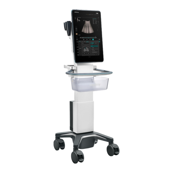
2.1.1 Intended Use The following Doppler ultrasound systems are used for clinical ultrasound diagnosis: TEX20, TEX20 Pro, TEX20S, TEX20T, TEX20 Exp, TEX20 Elite, TEX10, TEX10 Pro, TEX10S, TEX10T, TEX10 Exp, TEX10 Elite, TE X, TE X Lite. 2.1.2 System Appearance... -
Page 39: Peripherals Supported
Diagnostic Ultrasound System 2 Product Knowledge Service Manual Name Description Power button/indicator Used to power up or down the system. The indicator is on after the system is powered up. Power output port Supplies power to optional peripheral devices. The auxiliary power output outlet in the system is used to supply power to the recommended peripheral devices. -
Page 40: Specifications
Diagnostic Ultrasound System 2 Product Knowledge Service Manual Type Model Color video digital printer SONY UP-D25MD Footswitch 971-SWNOM (wired, two keys) 971-SWNOM (wired, three keys) 2.2 Specifications 2.2.1 Physical Specifications • Dimensions (folded state): (518±10) mm x (569±10) mm x (1303±10) mm •... -
Page 41: Product Principle
Diagnostic Ultrasound System 2 Product Knowledge Service Manual 2.3 Product Principle 2.3.1 Overall Architecture of Hardware System 2 2 . . 3 3 . . 1 1 . . 1 1 Hardware System Diagram Figure2–1 Block Diagram of the Overall Hardware System Architecture The hardware system of the TEX series product is divided into four units: frontend unit, backend unit, power supply unit, and UI unit. -
Page 42: Usb Distribution Scheme Of Main Board
Diagnostic Ultrasound System 2 Product Knowledge Service Manual The power supply unit supplies power to the frontend unit, backend unit, and peripherals. It converts AC input into DC voltage required by each module of the system, and completes battery charge and discharge management. •... -
Page 43: Video Extension Scheme
Diagnostic Ultrasound System 2 Product Knowledge Service Manual Function description: • The USB signals come from the PC module, always with three output USB 3.0 ports and one Type-C port. Only the first USB 3.0 port from top down in the rear of the main unit takes effect during BIOS startup. -
Page 44: Main Board Assembly
Diagnostic Ultrasound System 2 Product Knowledge Service Manual 2.3.4 Main board assembly 2 2 . . 3 3 . . 4 4 . . 1 1 Block Diagram of Main Board Figure2–4 Block Diagram of Main Board The frontend unit consists of the following boards: •... -
Page 45: Frontend Of The Main Board
Diagnostic Ultrasound System 2 Product Knowledge Service Manual 2 2 . . 3 3 . . 4 4 . . 2 2 Frontend of the Main Board Figure2–5 Block diagram of the main board front end The block diagram of the main board front end is shown in the preceding figure. The transmission and reception solution consists of eight MAX chips and eight AFE chips. -
Page 46: Backend Of The Main Board
Diagnostic Ultrasound System 2 Product Knowledge Service Manual • Receiving and caching of beam data • Image pre-processing in each mode • Data upload to the backend unit 7. Execution of front-end module reset, online upgrade, and module information management. 8. -
Page 47: Pc Module
Diagnostic Ultrasound System 2 Product Knowledge Service Manual • Support for 23.8-inch touch screen, with the resolution of 1920 x 1080. • Support for wired networks and wireless networks (M.2 port). • Support for SSD, with 256 GB or more storage (M.2 port). •... -
Page 48: Probe Board
Diagnostic Ultrasound System 2 Product Knowledge Service Manual 2.3.7 Probe Board 2 2 . . 3 3 . . 7 7 . . 1 1 Probe Board Figure2–7 Functional Block Diagram of Transducer Board The probe board connects and expands the probe channel with the transmitting and receiving channel in the main unit box. -
Page 49: Power Supply Unit
Diagnostic Ultrasound System 2 Product Knowledge Service Manual 2.3.8 Power Supply Unit 2 2 . . 3 3 . . 8 8 . . 1 1 Block Diagram of Power Supply Unit Figure2–8 Block Diagram of Power Supply Unit Excluding the internal power module on the board, the TEX main unit power supply also contains the following design elements: DC-DC power module, AC-DC adapter, and external battery. -
Page 50: Ac-Dc Board
Diagnostic Ultrasound System 2 Product Knowledge Service Manual 2 2 . . 3 3 . . 8 8 . . 2 2 AC-DC board Figure2–9 Block diagram of the AC-DC board As shown in the figure below, the base contains: AC-DC power module used to convert external AC input to 24 VDC voltage. -
Page 51: Battery Management Board
Diagnostic Ultrasound System 2 Product Knowledge Service Manual Function description: It provides a channel for peripheral AC power supply, with AC input and then AC output through the fuse. 2 2 . . 3 3 . . 8 8 . . 5 5 Battery Management Board Block diagram of battery management board Revision:1.0(2023-01-12) -
Page 52: Wireless Charging Module
Diagnostic Ultrasound System 2 Product Knowledge Service Manual Function description: The battery management board manages battery charge and discharge. It contains charge and discharge circuits of eight batteries. In addition, it provides the function of converting 24 VDC to 19 V for output. The power input includes battery input, 24 VDC input, and 18 V wireless input. -
Page 53: Timing Sequence Of System Power-On And Power-Off
Diagnostic Ultrasound System 2 Product Knowledge Service Manual The following figure shows the interconnection among modules in the charging pile and the wireless charging receiving module. Charging pile: 1. The wireless charging transmitting module (including the transmitting coil) converts the DC power supply into the transmission power supply. - Page 54 Diagnostic Ultrasound System 2 Product Knowledge Service Manual Battery power-on When batteries are used to supply power, the 5VSTB power supply is also turned off during power-off to reduce power consumption. When EC detects the PWR_BTN signal, 3V3STB_SM and 5VSTB are enabled to send the PC_PWR_BNT signal to the PC, after which the process is consistent with the power-on process with the AC power supply.
- Page 55 Diagnostic Ultrasound System 2 Product Knowledge Service Manual Waking up from standby by pressing a key When the device is in standby state, the PWR_BTN_N signal only needs to be transmitted to PC. After detecting that the PC_PWR_BTN_N signal is sent, PC increases the S3_N signal. The EC firmware turns on all power supplies and sends the PC_PWR_OK signal to PC, and then PC enters the startup state.
-
Page 56: Ui Unit
Diagnostic Ultrasound System 2 Product Knowledge Service Manual 2.3.9 UI Unit 2 2 . . 3 3 . . 9 9 . . 1 1 Block Diagram of the UI Unit According to ID design, TEX has no control panel, and the user interaction operations are all concentrated on the rotatable display assembly with the touch function. -
Page 57: Monitor Assembly
Diagnostic Ultrasound System 2 Product Knowledge Service Manual • IO module: It is used for inputs and outputs of audio and video signal, network signal, and USB port information. 2 2 . . 3 3 . . 9 9 . . 2 2 Monitor Assembly Block diagram of the display assembly Figure2–18 Block diagram of the display assembly... -
Page 58: Display Conversion Board
Diagnostic Ultrasound System 2 Product Knowledge Service Manual Power supply: 12 V±5%. The signal is HDMI signal. The screen can be rotated by 0 degrees or 90 degrees. The UI automatically adapts to the landscape and portrait modes. 2 2 . . 3 3 . . 9 9 . . 3 3 Display conversion board The display conversion board has the following functions: The display conversion board contains only two sockets. -
Page 59: Wireless Probe Charging Station
Diagnostic Ultrasound System 2 Product Knowledge Service Manual 2.3.10 Wireless Probe Charging Station 2 2 . . 3 3 . . 1 1 0 0 . . 1 1 Wireless Probe Charging Station (Not Released) The wireless probe charging station provides the wireless probe holder function for the TEX trolley, so as to support quick charging for three wireless probes. - Page 60 Diagnostic Ultrasound System 2 Product Knowledge Service Manual The ECG module is designed for monitoring ECG signals and displaying ECG waveforms, which serve as reference of ultrasound images and keep synchronous with 2D images and color flow images displayed in real time. After being amplified, filtered, and sampled, the ECG signal is sent to the DSC module through the UART serial port.
-
Page 61: System Power-On Control
Diagnostic Ultrasound System 2 Product Knowledge Service Manual 2.3.12 System Power-on Control 2 2 . . 3 3 . . 1 1 2 2 . . 1 1 System Power-on Control Revision:1.0(2023-01-12) -
Page 62: Probes And Needle Guides
Diagnostic Ultrasound System 2 Product Knowledge Service Manual 2.4 Probes and Needle Guides 2.4.1 Probes Image Model Informa- Remarks tion C5-1s Probe type Convex Applicable NGB-022 needle Metal- guide needle detachable Probe type Convex C4-1s released Applicable NGB-036 needle Metal- guide needle detachable... - Page 63 Diagnostic Ultrasound System 2 Product Knowledge Service Manual Image Model Informa- Remarks tion Applicable NGB-016 needle Metal- guide needle detachable L14-6Ns Probe type Linear Applicable NGB-007 needle Plastic- guide needle detachable Metal- needle detachable L9-3s Probe type Linear Applicable NGB-034 needle Metal- guide...
- Page 64 Diagnostic Ultrasound System 2 Product Knowledge Service Manual Image Model Informa- Remarks tion L11-3VNs Probe type Linear Applicable None needle guide L12-3VNs Probe type Linear Applicable None needle guide L14-3Ws Probe type Linear released Applicable NGB-054 needle Metal- guide needle detachable V11-3Hs Probe type Convex...
- Page 65 Diagnostic Ultrasound System 2 Product Knowledge Service Manual Image Model Informa- Remarks tion Metal- needle detachable P10-4s Probe type Phased array released Applicable None needle guide P8-2s Probe type Phased array released Applicable None needle guide Probe type Phased array Applicable None needle...
-
Page 66: Needle Guides
Diagnostic Ultrasound System 2 Product Knowledge Service Manual Image Model Informa- Remarks tion P8-3Ts Probe type Phased array released Applicable None needle guide P8-2Ts Probe type Phased array Applicable None needle guide LAP13-4Cs Probe type Convex released Applicable None needle guide 2.4.2 Needle Guides Image... - Page 67 Diagnostic Ultrasound System 2 Product Knowledge Service Manual Image Model Informa- Remarks tion Type Metal-needle NGB-011 detachable Biopsy 11° and 23° angle/depth Applicable 13G, 15G, Biopsy 16G, 18G, Needle 20G, and NGB-018 Type Metal/needle undetacha Biopsy 15°, 25°, and angle/depth 35°...
- Page 68 Diagnostic Ultrasound System 2 Product Knowledge Service Manual Image Model Informa- Remarks tion Type Metal-needle NGB-043 detachable Biopsy Range: 35° angle/depth to 80°. Applicable 20G, 21G, Biopsy 22G, and Needle NGB-044 Type Metal-needle detachable Biopsy Biopsy angle/depth depth: 5 mm, 10 mm, 15 mm, 25 mm, and 35 mm...
-
Page 69: Installation
Diagnostic Ultrasound System 3 Installation Service Manual 3 Installation 3.1 Site Preparations 3.1.1 Environmental Requirements 3 3 . . 1 1 . . 1 1 . . 1 1 Environmental Requirements Operating Environment Storage and transportation environment Ambient temperature 0°C to 40°C –20°C to +55°C Relative humidity 20%-85% (no condensation) -
Page 70: Emi Limitation
Diagnostic Ultrasound System 3 Installation Service Manual Voltage 100–240VAC Frequency 50/60Hz Power consumption 240 VA It is the sum of maximum output power on all auxiliary power output ports. Make sure the total output power does not exceed this value when the system is connected to optional peripherals. -
Page 71: Package Specifications
Diagnostic Ultrasound System 3 Installation Service Manual Possible EMI sources include scanners, medical lasers, monitors, mobile phones, and cautery units. In addition, radio transceivers, radio-controlled toys, and other devices that may radiate high-frequency radio waves cannot be used in the same room as the system. If such devices are available in the room, turn them off to ensure the proper operation of the system. -
Page 72: Space Requirements
Diagnostic Ultrasound System 3 Installation Service Manual 3.1.5 Space Requirements 3 3 . . 1 1 . . 5 5 . . 1 1 Physical Dimensions 3 3 . . 1 1 . . 5 5 . . 2 2 Space Requirements Place the ultrasonic system equipped with necessary accessories in an appropriate place that meets the following requirements:... -
Page 73: Network Requirements
Diagnostic Ultrasound System 3 Installation Service Manual 1. The room is well ventilated or equipped with an air conditioning system. 2. There are sufficient clearances behind and at both sides of the system. Otherwise, the system may overheat and malfunction. 3. -
Page 74: Unpacking
1. Before unpacking the device, check whether the package is intact. If the outer package is damaged, take pictures as evidence. 2. Check whether the unpacked device is intact. If any damage is found, contact the Mindray branch or headquarters immediately and keep the evidence. -
Page 75: Unpacking Tools
Diagnostic Ultrasound System 3 Installation Service Manual 3. Unpack the device in a spacious place and check the items in the package against the packing list. • The device must be inspected in the presence of physicians from the ultrasound department and personnel from the equipment department or other personnel authorized by the hospital. - Page 76 Diagnostic Ultrasound System 3 Installation Service Manual 2. Remove the wooden roof and place it in the front of the device (this side faces outward) as a slope. Outward facing label 3. Release the wall clamp. a. When the space above is sufficient, take the wall clamp up directly. b.
- Page 77 Diagnostic Ultrasound System 3 Installation Service Manual outward at the same time. Pull all the four buckles out of the wall clamp and take the wall clamp off after releasing it. 4. Take off the top foam, accessory package, display package, main unit box package, lithium battery package, and probe package in sequence.
- Page 78 Diagnostic Ultrasound System 3 Installation Service Manual 6. Push the device from the pallet of the slope. When the main unit box and display are not installed for the trolley, do not press the lift switch on the handle when pushing down the machine from the pallet of the slope to prevent the trolley from bounce and hurting people.
-
Page 79: Checking Unpacked Items
Take out the packing list from the packing box and check the unpacked items against the packing list. If any parts or accessories on the packing list are absent, contact the Mindray branch or headquarters promptly and take pictures as evidence. -
Page 80: Installation Of Whole Device
Diagnostic Ultrasound System 3 Installation Service Manual • Transport in an elevator Make sure the elevator door is more than 570mm wide so that the main unit can be moved in. 3.4 Installation of Whole Device 3.4.1 Connecting the External Power Supply Connect the plug at the other end of the power cable to a power outlet. - Page 81 Diagnostic Ultrasound System 3 Installation Service Manual Main unit box assembly Boss of the main unit back cover Main unit support groove 2. Pull down the spring plunger, push the lower part of the main unit box assembly to the bottom, and loosen the spring plunger.
- Page 82 Diagnostic Ultrasound System 3 Installation Service Manual Lower part of the main unit box assembly Push back Spring plunger Pull down and reset After installation, ensure that the spring plunger correctly rebounds. The method of determining whether the spring plunger correctly rebounds is as follows: 1.
-
Page 83: Installing The Display Assembly
Diagnostic Ultrasound System 3 Installation Service Manual 3. Put your fingers on the clasping position of the cable cover, and pull the upper part of the cable cover outward to open the cable cover. Put the magnetic plug near the magnetic socket. The magnetic plug will automatically attract to the correct position of the socket, implementing automatic installation and closing the cable cover. - Page 84 Diagnostic Ultrasound System 3 Installation Service Manual Front of the display assembly Rear of the display assembly Unlocking lever Column 2. Hold the display assembly upright with your hands, observe the mounting groove on the rear of the display assembly, approach the rotating disk of the main unit box assembly from top down, center the display and the main unit box assembly roughly in the left and right directions, and place the display assembly on the rotating disk.
-
Page 85: Installing The Storage Basket
Diagnostic Ultrasound System 3 Installation Service Manual Centering mark Rear of the display assembly Ensure that the unlocking lever correctly returns. The method of determining that the unlocking lever correctly returns is as follows: 1. No exceptions such as convex occur on the unlocking lever. 2. -
Page 86: Installing The Big Probe Holder And The Small Probe Holder
Diagnostic Ultrasound System 3 Installation Service Manual Storage basket opening Storage basket mounting position Front Column mounting position After mounting, press the storage basket downward to ensure that it is mounted correctly and reliably. Otherwise, it may fall, damaging the device and hurting people. 3.4.5 Installing the Big Probe Holder and the Small Probe Holder 1. - Page 87 Diagnostic Ultrasound System 3 Installation Service Manual Holder opening Holder mounting position Probe mounting position on the main unit shell Big Probe Holder Small Probe Holder After mounting, press the Big Probe Holder and Small Probe Holder downward to ensure that they are mounted correctly and reliably. Otherwise, they may fall, damaging the device and hurting people.
-
Page 88: Installing Batteries
Diagnostic Ultrasound System 3 Installation Service Manual 3.4.6 Installing Batteries 1. Lift the trolley to the highest position. 2. Use your hands to hold the two sides of the rear on the battery box and lift it up to take off the battery box back cover. -
Page 89: Installing The Wireless Probe Charging Station
Diagnostic Ultrasound System 3 Installation Service Manual 3.4.7 Installing the Wireless Probe Charging Station 1. Connect the power cord of the Wireless Probe Charging Station to the charging socket of the trolley. 2. Then, align the Wireless Probe Charging Station with the two protruding positioning points on the hook decoration cover and press down to mount the Wireless Probe Charging Station on the trolley. - Page 90 Diagnostic Ultrasound System 3 Installation Service Manual 2) Hold the Charging Pile module(China) with both hands, and insert the Charging Pile module (China) on the base from top to bottom. Pay attention to the mounting direction. The left figure shows the mounting procedure while the right figure shows that it is mounted. 3) Turn over the mounted assemblies with the back facing forward, and then use a Phillips screwdriver to mount the two countersunk screws in the red area indicated in the figure below.
- Page 91 Diagnostic Ultrasound System 3 Installation Service Manual 5) Tear off the release paper on the rear of the cushion pads. Cushion pads can be thick or thin but with the same length and width. Observe the condition of the wall where the Charging Pile module(China) is installed.
- Page 92 Diagnostic Ultrasound System 3 Installation Service Manual 7) Connect the power supply. The power socket is at the bottom of the right side of the module. Pay attention to the connection direction. Then, use Velcro tapes to arrange the power cord. 2.
- Page 93 Diagnostic Ultrasound System 3 Installation Service Manual 3) Use a churn drill to drill holes at the four marked positions, with a diameter of 6 mm and a depth of 30 mm. 4) Hammer the four expansion screws (white) inside the wall mounting rack into the four holes. 5) Use the self-tapping screws inside the wall mounting rack to mount the wall mounting rack on the wall (the four holes of the wall mounting rack are aligned with the four holes on the wall).
- Page 94 Diagnostic Ultrasound System 3 Installation Service Manual Wireless Charging Module Mounting Rack Wireless charging module Slot Screws tightened by hand 2. Insert the wireless cable plug-in terminal into the wireless charging module, and press the magnetic ring into the baffle at the same time. 3.
-
Page 95: Connecting The Probe
When connecting or disconnecting the probe, place it in a proper position, to prevent the probe from falling off or becoming damaged. • Only use the probes provided by Mindray. Aftermarket probes may result in damage or cause a fire. Connecting the Probe Before connecting the probe, make sure the probe, probe cable, and probe connector are free from cracks or peeling surface. -
Page 96: Adjusting The System
Diagnostic Ultrasound System 3 Installation Service Manual 3. Route the probe cable in an appropriate place to protect it from trampling. Make sure the cable is not twisted with other objects. Place the probe head in a safe place to protect it from collisions. -
Page 97: Connecting Peripherals
Diagnostic Ultrasound System 3 Installation Service Manual When the display is in the portrait mode, the display angle can be adjusted backward, as shown in the following figure. 3.6 Connecting Peripherals 3.6.1 Connecting the Footswitch Do not connect more than one footswitch to the main unit, as doing so may cause the system to malfunction. -
Page 98: Connecting The Graphic/Text Printer
Diagnostic Ultrasound System 3 Installation Service Manual 4. Install the printer driver as follows: 1) On the peripheral settings screen, tap the Printer Driver tab. 2) Tap Add Printer. Note: see the printer’s operation manual to select the port, or use the default port of the system. -
Page 99: Connecting The Wireless Printer
Diagnostic Ultrasound System 3 Installation Service Manual 5. Choose About>Peripherals to access the printing service screen. 1) Select Report Print in the Service Type column. 2) Select the printer in the Property section and set the printing parameters. 3) Click OK to complete the settings. 3.6.4 Connecting the Wireless Printer The system can connect to a wireless graph/text printer to print reports. -
Page 100: Software Setup
Diagnostic Ultrasound System 3 Installation Service Manual 4. When the ultrasound equipment is running (without the need to install a driver program), press the scan trigger switch to scan barcode information. For other usage methods, see the barcode scanner manual. If the barcode scanner does not work, check whether it is configured correctly, for example, whether its Enter key is configured. -
Page 101: Entering The Doppler Screen
Diagnostic Ultrasound System 3 Installation Service Manual 3.7.2 Entering the Doppler Screen After the system starts, it performs initialization (taking about 30s) and displays the Doppler screen, as shown in the following figure. 3.7.3 Setting Hospital Information 1. Tap the icon in the upper right corner, and choose Setup in the tool bar to access the setup menu. -
Page 102: Setting The Screensaver And Standby Mode
Diagnostic Ultrasound System 3 Installation Service Manual 3.7.6 Setting the Screensaver and Standby Mode On the setup screen, choose System>General, and set the screensaver and standby mode in the Screen Saver area. 3.7.7 Setting the Image/Clip Storage On the setup screen: •... -
Page 103: Setting The Printer
Diagnostic Ultrasound System 3 Installation Service Manual Choose About>Key Probe and you can set or view information related to the wireless probe. 3.7.10 Setting the Printer On the setup screen, choose About>Peripherals in the navigation pane, and set the printing service and image parameters. -
Page 104: Setting The Footswitch
Diagnostic Ultrasound System 3 Installation Service Manual Item Description Default Print Service Sets a selected service as the default printing service. PROPERTY Allows you to set the properties of a selected service, such as the service type and paper size. Two service types are supported: report printing and digital printing. - Page 105 If both 1D and 2D default items are configured, the matching priorities after barcode scanning is as follows: 2D, 1D, and default items. Import/Export Preconfigure barcodes by importing or exporting configuration files. For details, Mindray Customer Service Department or sales representative. • 2D Barcode Scanner "Normal" parsing mode Revision:1.0(2023-01-12)
- Page 106 Diagnostic Ultrasound System 3 Installation Service Manual The barcode is comprised of the patient ID, other IDs, patient name, DOB, and other information. Setup items are described as follows: Item Description Barcode Enter a barcode and the system automatically separates the barcode example into the list in the lower part based on separators, which set the start position and end position of different information items.
- Page 107 Import/Export Preconfigure barcodes by importing or exporting configuration files. For details, Mindray Customer Service Department or sales representative. "Advanced" parsing mode Scan a barcode consisting certain information of the hospital, enter a regular expression based on the barcode format, and tap Match to match the scanned barcode with the regular expression.
-
Page 108: Connecting To The Network
Service Manual – Import/Export: Preconfigure barcodes by importing or exporting configuration files. For details, Mindray Customer Service Department or sales representative. 3.7.13 Connecting to the Network Enable Wi-Fi. 1. After the system starts, tap Setup in the upper right corner of the screen to display the setup screen. - Page 109 Diagnostic Ultrasound System 3 Installation Service Manual Enable remote maintenance. Select Remote Maintenance Permission to enable remote maintenance of the system. Click Upload Logs to Remote Server to upload logs to the server, so that customer service engineers can obtain these logs from the server for problem analysis. View the task uploading progress on the Patient Task Manager page.
- Page 110 Diagnostic Ultrasound System 3 Installation Service Manual Category Item Description Document IP Address Enter the ADT data source IP address of the ADT sharing application gateway in the eGateway server pre- service configuration. Port Enter the SSL port of document sharing in the eGateway server pre-configuration.
-
Page 111: Setting The Dicom/Hl7
Diagnostic Ultrasound System 3 Installation Service Manual Item Description Password Visible Specifies whether the worksheet password is displayed in plaintext. Import Imports a custom worksheet template from the USB flash drive (exported from the Q-Path server). Backup Backs up the worksheet template on the USB flash drive. Restore Loads the backup worksheet template from the USB flash drive to the ultrasonic system. - Page 112 Diagnostic Ultrasound System 3 Installation Service Manual • AE Title of the local computer should be the same as the SCU AE Title preset in the server (PACS/RIS/HIS). For example, if the AE Title of the printer server is set to Printer, and the AE of the acceptable SCU is preset as Machine, then in the figure above, the AE Title should be Machine (indicating that the ultrasonic machine is SCU), and the AE Title of the print server should be Printer.
- Page 113 Diagnostic Ultrasound System 3 Installation Service Manual Item Description • Manage certificates, including the importing and removing certificates. Set the server Device Name Server name (name of the device supporting DICOM services). IP Address IP address of the server. Ping Determines whether the connection is successful.
- Page 114 Diagnostic Ultrasound System 3 Installation Service Manual • Adding policies: Set Policy name and Description, click Add to add new policies. Added policies will appear in the policy list. • Deleting strategies: Select the custom policies in the policy list and click Delete. •...
- Page 115 Diagnostic Ultrasound System 3 Installation Service Manual 4. Select a service in the service list, and click Verify to verify the connection between the DICOM application entities. If the verification succeeds, Verification succeeded appears in the status bar. Otherwise, Verification failed appears. If the verification fails, the possible causes may be: wrong IP address, inaccessible IP address, remote DICOM service that is not running, wrong port configured, and inconsistent application entity titles.
- Page 116 Service Manual Item Description • Data source: used to obtain 3D/4D images for 4DViewer, which is a private method of Mindray. Storage Setting of Set the structured report sending function. Structured Report Encapsulate PDF Select whether to encapsulate the measurement reports in PDF format according to DICOM standards.
- Page 117 Diagnostic Ultrasound System 3 Installation Service Manual DICOM print setting items are described as follows: Item Description Device Name After you set a server in DICOM Server Setting, the name will appear in the drop-down list. Select the name of the configured print server. Service Name Specifies the service properties.
- Page 118 Diagnostic Ultrasound System 3 Installation Service Manual Item Description Magnification Type Select the printer magnifying an image to fit the film. • Replicate: Interpolated pixels belong to duplicate of adjacent pixels. • Bilinear: Interpolated pixels are generated from bilinear interpolations between adjacent pixels. •...
- Page 119 Diagnostic Ultrasound System 3 Installation Service Manual Item Description Interval Time (s) Reserved function. Timeout The time after which the system will stop trying to establish a connection to the service. Secure transmission layer protocol. Select whether to encrypt the data transferred over the network.
- Page 120 Diagnostic Ultrasound System 3 Installation Service Manual Item Description Device Name After you set a server in DICOM Server Setting, the name will appear in the drop-down list. Select the name of the storage commitment server. Service Name Specifies the service properties. AE Title Application entity title.
- Page 121 Diagnostic Ultrasound System 3 Installation Service Manual Item Description Timeout Value: 5-60s, in increments of 5s, and 15s by default. The connection is disabled if no image and information is received in 15 seconds after the user receives information or images. Secure transmission layer protocol.
-
Page 122: Setting User Permissions
Diagnostic Ultrasound System 3 Installation Service Manual 3.7.15 Setting User Permissions 1. After the system starts, tap Setup on the touch screen to display the setup screen. 2. On the setup screen, choose System>Access Control to open the user permission setup screen. - Page 123 Diagnostic Ultrasound System 3 Installation Service Manual Select or clear the check box corresponding to a permission item to add or delete permissions. Tap OK to confirm the settings and exit the dialog box. 5) Modify Password The system administrator can modify passwords of all users. The default administrator password is null.
- Page 124 Diagnostic Ultrasound System 3 Installation Service Manual Item Description Remarks Locking For example, the locking Specifies the maximum number of threshold consecutive times that a user can enter a threshold is set to 5, time for wrong password. If this threshold is resetting locking threshold to exceeded, the corresponding account will 60 minutes, and locking...
- Page 125 Diagnostic Ultrasound System 3 Installation Service Manual Item Description Default Domain The default domain is the DC name in the root DN. For example, if the DC name is security1 in the root DN, the default domain is security1. Password Retention This item specifies the number of days that an LDAP user Period password is retained locally.
-
Page 126: Setting The Security Policy
Diagnostic Ultrasound System 3 Installation Service Manual Item Description Verification Test Enter the group user name and password in the User Name and Password editing boxes. Tap Login Test to verify whether the user can be authenticated. The screen will display the authentication result. Enable Custom After custom properties are enabled, the group and permission list Properties... - Page 127 The password does not support input multi-language or Chinese characters. Antivirus The system provide anti-virus software to protect the machine from viruses, spyware, and other malicious software. Anti-virus software is optional. To purchase it, contact Mindray Customer Service Department or sales representative. Revision:1.0(2023-01-12)
-
Page 128: Function And Performance Check
Diagnostic Ultrasound System 4 Function and Performance Service Manual Check 4 Function and Performance Check 4.1 Description 4.1.1 Description This chapter describes only the recommended check processes. 4.2 Device Status Check 4.2.1 Running Status 1. Check whether the ultrasonic device can be normally powered on and shut down (the startup and closing time is within the allowed range) and whether the device runs properly without any noise or error. -
Page 129: Routine Check
Diagnostic Ultrasound System 4 Function and Performance Service Manual Check 4.3 Routine Check 4.3.1 Check Process 4 4 . . 3 3 . . 1 1 . . 1 1 Check Process Revision:1.0(2023-01-12) -
Page 130: Check Items
Diagnostic Ultrasound System 4 Function and Performance Service Manual Check 4.3.2 Check Items 4 4 . . 3 3 . . 2 2 . . 1 1 Checking the Display Procedure Acceptance criteria • • Adjust the display brightness/contrast Brightness adjustment •... -
Page 131: Checking The Touch Panel
Diagnostic Ultrasound System 4 Function and Performance Service Manual Check Procedure Acceptance criteria The area inside the rectangular box with black/white background is the image area. 4 4 . . 3 3 . . 2 2 . . 2 2 Checking the Touch Panel Procedure Acceptance criteria... -
Page 132: Checking The Ecg Function
Diagnostic Ultrasound System 4 Function and Performance Service Manual Check 4 4 . . 3 3 . . 2 2 . . 4 4 Checking the ECG Function Procedure Acceptance criteria After confirming that the system has the ECG is activated. ECG waveforms and a heart optional ECG function, set ECG to On. -
Page 133: Check Items
Diagnostic Ultrasound System 4 Function and Performance Service Manual Check 4.4.2 Check Items 4 4 . . 4 4 . . 2 2 . . 1 1 Checking All Image Modes B Mode In B mode image scanning, the image parameter area on the left side of the screen displays the real-time parameter values as follows: Revision:1.0(2023-01-12) - Page 134 Diagnostic Ultrasound System 4 Function and Performance Service Manual Check Parame- Zoom Descrip Depth Gain Frame Zoom factor Speed of tion quen rate (Not displayed when the factor sound is 1.0) The following parameters can be adjusted during B mode image scanning. Adjustment method Parameter Adjust on the right of the image area...
- Page 135 Diagnostic Ultrasound System 4 Function and Performance Service Manual Check Procedure Acceptance criteria decrease the depth. The adjustable depth values vary depending upon the probe types. Move the cursor rightward to increase the gain. Then the image turns bright in the corresponding area.
- Page 136 Diagnostic Ultrasound System 4 Function and Performance Service Manual Check Procedure Acceptance criteria Tap L/R Flip in the image menu for adjustment. mark indicates the default orientation of an image in the upper left corner. iClear Range: Tap iClear in the image menu for adjustment. Off, 1-7 V1:1 (only for linear array probes) The Dual function needs to be turned on for...
- Page 137 Diagnostic Ultrasound System 4 Function and Performance Service Manual Check Procedure Acceptance criteria Tap ImageMenu>A. Power for adjustment. The A. Power value is displayed in real time in the upper part of the screen. U/D Flip It can rotate images upward or downward. Tap ImageMenu>U/D Flip for adjustment.
- Page 138 Diagnostic Ultrasound System 4 Function and Performance Service Manual Check In Color mode image scanning, the image parameter area on the left side of the screen displays the real-time parameter values as follows: Parameter Description Transmission Color gain Color wall filter Pulse repetition frequency rate...
-
Page 139: Checking Basic Measurements
Diagnostic Ultrasound System 4 Function and Performance Service Manual Check Parame- Angle Descrip Transmis SV depth SV size Correction angle tion sion frequency Parameters that can be adjusted to optimize the PW/ CW mode image are indicated in the following. Adjustment method Parameter Adjustment in the image area... -
Page 140: Checking The Cine Mode
Diagnostic Ultrasound System 4 Function and Performance Service Manual Check 4 4 . . 4 4 . . 2 2 . . 3 3 Checking the Cine Mode Procedure Acceptance criteria The system enters the cine review state. Tap the icon to freeze the image. -
Page 141: Checking Usage Of The Probe
Diagnostic Ultrasound System 4 Function and Performance Service Manual Check 4 4 . . 4 4 . . 2 2 . . 4 4 Checking Usage of the Probe Procedure Acceptance criteria Insert the probe into the probe socket of the The convex probe and linear probe are connected. -
Page 142: Performance Test
Diagnostic Ultrasound System 4 Function and Performance Service Manual Check 4.5 Performance Test 4.5.1 Test Process 4 4 . . 5 5 . . 1 1 . . 1 1 Test Process Revision:1.0(2023-01-12) - Page 143 Diagnostic Ultrasound System 4 Function and Performance Service Manual Check 4.5.2 Test Items 4 4 . . 5 5 . . 2 2 . . 1 1 Transverse Resolution • For the convex probe, keep the transverse resolution targets near the central line of the scanning plane.
- Page 144 Diagnostic Ultrasound System 4 Function and Performance Service Manual Check 1. Place the probe gently on the acoustic window of the phantom which is covered by water or ultrasonic gel. Ensure that the axial resolution targets are displayed in the center of the image. 2.
- Page 145 Diagnostic Ultrasound System 4 Function and Performance Service Manual Check 4 4 . . 5 5 . . 2 2 . . 4 4 Axial Geometric Positioning Accuracy • The measurement cursor should be placed on the top edge of the target image, not in the middle or bottom edge.
- Page 146 Diagnostic Ultrasound System 4 Function and Performance Service Manual Check 3. Select all measurement values deviating largely from 20mm, and calculate the error by the following formula. The image effect is shown in the figure below: 4 4 . . 5 5 . . 2 2 . . 5 5 Lateral Geometric Positioning Accuracy •...
- Page 147 Diagnostic Ultrasound System 4 Function and Performance Service Manual Check The image effect is shown in the figure below: 4 4 . . 5 5 . . 2 2 . . 6 6 Dead Zone • For the linear probe, the probe surface should be perfectly fit with the acoustic window on the phantom without any inclination.
- Page 148 Diagnostic Ultrasound System 4 Function and Performance Service Manual Check Revision:1.0(2023-01-12)
- Page 149 Diagnostic Ultrasound System 5 Maintenance Service Manual 5 Maintenance 5.1 Care and Maintenance 5.1.1 Overview 5 5 . . 1 1 . . 1 1 . . 1 1 Description The ultrasound system does not require regular preventative maintenance such as calibration or adjustments to the hardware and transducers.
- Page 150 Diagnostic Ultrasound System 5 Maintenance Service Manual Table 5–2 Tools and measuring devices(continued) Consumables Quantity Remarks Mild soapy water About 400 mL Dry soft cloth or cotton cloth About 5 pcs 5 5 . . 1 1 . . 1 1 . . 3 3 Routine Maintenance Items Table 5–3 Maintenance items and maintenance frequency Item...
- Page 151 Diagnostic Ultrasound System 5 Maintenance Service Manual Table 5–3 Maintenance items and maintenance frequency(continued) Item Recommend- Operator Method Terminal Engineer Frequency users ● Electrical Safety Once per year Inspection 5.1.2 System Cleaning 5 5 . . 1 1 . . 2 2 . . 1 1 Flow of Cleaning Figure5–1 Flow of Cleaning The touch screen can be cleaned when the device is turned on: Select Lock Screen in...
- Page 152 Diagnostic Ultrasound System 5 Maintenance Service Manual • Tool: soft brush • Method: 1. Before cleaning, remove the dust-proof net. In the direction shown in the figure below, press the elastic buckle of the dust-proof net cover upwards and turn it outward to remove the dust- proof net.
- Page 153 Diagnostic Ultrasound System 5 Maintenance Service Manual 5 5 . . 1 1 . . 2 2 . . 5 5 Cleaning the Probe Holder • Tools: mild soapsuds, dry soft cloth, and soft brush • Method: 1. Use a dry soft cloth to wipe the dust inside and outside the probe and the gap of the holder. For the small cavity probe holder or gap, use a soft brush to gently brush off the dust and stains from the inner layer.
- Page 154 Do not mix different disinfectants. Otherwise, it may cause injury. • Mindray makes no claims regarding the efficacy of the listed chemicals or methods as a means for controlling infection. For the method to control infection, consult your hospital’s Infection Control Officer or Epidemiologist.
- Page 155 • If you accidentally pour the liquid on the main unit, please disconnect the power immediately, wipe the liquid, and contact the maintenance personnel or Mindray. • Never use abrasive materials (such as steel wool or silver polish), or erosive cleaners (such as acetone or acetone-based cleaners) for cleaning.
- Page 156 Diagnostic Ultrasound System 5 Maintenance Service Manual Reagent name Reagent name Type WIP ANIOS clean up Laboratoires ANIOS Wet wipes WIP ANIOS Premium Laboratoires ANIOS Wet wipes VIREX TB Diversey Inc. Solutions Sani-Cloth® Prime Wet wipes Sani-Cloth® Bleach Wet wipes Wet wipes Sani-Cloth®...
- Page 157 Diagnostic Ultrasound System 5 Maintenance Service Manual 5.1.3 Inspection 5 5 . . 1 1 . . 3 3 . . 1 1 General Inspections Table 5–5 Common inspections Content Method • Probes Visually check the head of the probe for cracks or expansion.
- Page 158 Diagnostic Ultrasound System 5 Maintenance Service Manual Table 5–6 System function inspection checklist Content Method B Mode Check the basic operations of the B mode. Check some of the basic software and hardware that affects operations related to the B mode. Color mode Check the basic operations of the color mode.
- Page 159 Diagnostic Ultrasound System 5 Maintenance Service Manual Table 5–7 Inspection of optional functions, peripherals and accessories(continued) Item Content Method Footswitch Check whether the footswitch implements the configured functions according to the program. DVD-R/W Check whether DVD-R/W is working properly (burning, reading and ejecting).
-
Page 160: Electrical Safety Inspection
Diagnostic Ultrasound System 5 Maintenance Service Manual Item Content Method Tool Caster Visually check that the casters are not None broken. Turn on and off the caster locks to ensure that casters can be locked and released properly. Caster connection Visually check that the casters are not Socket head wrench askew and whether the connecting... -
Page 161: Software Maintenance
Diagnostic Ultrasound System 5 Maintenance Service Manual 5.2 Software Maintenance 5.2.1 Viewing System Information 5 5 . . 2 2 . . 1 1 . . 1 1 Viewing System Information • Verify the system information before and after software maintenance. •... -
Page 162: Logging In As The Service User
Diagnostic Ultrasound System 5 Maintenance Service Manual 5.2.2 Logging in as the Service User 5 5 . . 2 2 . . 2 2 . . 1 1 Logging In to the Service Account Login method: 1. Use one of the following methods to access the login dialog box and log in to the system as the Service user: •... - Page 163 Diagnostic Ultrasound System 5 Maintenance Service Manual 2. After logging into the system as service, choose Setup>Maintenance>Setup to access the corresponding maintenance menu: Revision:1.0(2023-01-12)
-
Page 164: Importing Configuration File After Ssd Replacement
When you turn on a TEX series machine for the first time after replacing SSD, the system will prompt importing the configuration file. Perform the following steps: 1. After replacing SSD, contact Mindray after-sales service engineer to download the configuration file from Mindray internal platform. - Page 165 Diagnostic Ultrasound System 5 Maintenance Service Manual 3. Insert the USB drive to the USB interface, and start the machine. The system prompts you to import the configuration file. 4. Click Import Configuration, select the key folder in the USB drive, and then click OK. After the file is imported, the system prompts "Imported successfully".
-
Page 166: Recovering The Software
Diagnostic Ultrasound System 5 Maintenance Service Manual 5.2.4 Recovering the Software 5 5 . . 2 2 . . 4 4 . . 1 1 Recovering the Software For details, see the System Recovery Guide. 5.2.5 Self-Tests 5 5 . . 2 2 . . 5 5 . . 1 1 Self-test Introduction The self-test function is inherent in the TEX series and aims to test the connections of hardware boards and the running status of the system. - Page 167 Diagnostic Ultrasound System 5 Maintenance Service Manual If the language of the current Doppler system is Chinese, a Chinese page of the self-test program is displayed. If the language of the current Doppler system is not Chinese, an English interface of the self-test program is displayed.
- Page 168 Diagnostic Ultrasound System 5 Maintenance Service Manual 4. On the maintenance self-test main page, you can pre-configure the corresponding test items by referring to the following table. Click Start to enter the maintenance self-test state after the configuration is completed. Function Button or Check Open All...
- Page 169 Diagnostic Ultrasound System 5 Maintenance Service Manual Button or Check Function Shut Down Click this button to close the program, and the machine shuts down automatically. If the test report is not saved, the system will prompt you whether to save the test report to the mobile storage medium before shutdown.
- Page 170 Diagnostic Ultrasound System 5 Maintenance Service Manual When the self-test program is running, the self-test software version is displayed in the upper left corner on the status bar: Version of the self-test software in TEX customer service mode: xx Release date: xxxx-xx-xx During testing, the software version information in the status bar changes to the name of the current test item.
- Page 171 Diagnostic Ultrasound System 5 Maintenance Service Manual Figure5–6 Display of test results in the test item list Click a test item in the list, and the program will automatically index the detailed test results corresponding to the test item, and display the test results in detail, as shown in the figure below.
-
Page 172: User Self-Test
Diagnostic Ultrasound System 5 Maintenance Service Manual the first-level directory, and 01 indicates that "Parameter board I2C communication test" is the first test item under "Main display". 5 5 . . 2 2 . . 5 5 . . 3 3 User Self-Test Turn on the machine, tap Setup, and choose Maintenance>Setup>Self-test for a self-test. -
Page 173: Test Report
Diagnostic Ultrasound System 5 Maintenance Service Manual Button or Check Box Description Save Report Click this button to save the test data to the root directory under the specified logical drive letter. This button is unavailable during the test or if no logical drive letter is selected. Shut Down Click this button to close the program, and the machine shuts down automatically. - Page 174 Diagnostic Ultrasound System 5 Maintenance Service Manual On the left is a list of test items, which are classified according to test results. When you click a test item on the left, the report automatically indexes the test data for that test item. On the right is the test information, which includes the following contents: 1.
- Page 175 Diagnostic Ultrasound System 5 Maintenance Service Manual Where, Z0204: ID of the test item; Board/Module: board or module where the test item is located; Test Result: result of the test item; Information: test information. Saving of test data The test report is named by time and packaged in a.zip file. The test report will be saved in the /mrcs/d/TEX/Log/SelftestReport directory, and up to 20 test reports can be saved.
-
Page 176: Exporting And Viewing Logs
Diagnostic Ultrasound System 5 Maintenance Service Manual 3. For detailed explanation of the self-test items, see 9.3 Description of Self-Test Items Without the mobile storage medium inserted on the computer, users cannot export the data. 5.2.6 Exporting and Viewing Logs 5 5 . -
Page 177: Viewing Logs
Diagnostic Ultrasound System 5 Maintenance Service Manual 5 5 . . 2 2 . . 6 6 . . 2 2 Viewing Logs 1. Log in to the system as Service. 2. Choose Setup>Maintenance>Log Manager to enter the following interface: Type Item Description... -
Page 178: Optional Software Function Management
Diagnostic Ultrasound System 5 Maintenance Service Manual Type Item Description Clear All Logs Click this button to delete all logs in the system. Clear Logs Before Enter the number of days and click this button to delete the log generated before the number of days entered. -
Page 179: Uninstalling Optional Functions
Diagnostic Ultrasound System 5 Maintenance Service Manual 3. Click Install. In the displayed Open File dialog box, select the corresponding key file and click 4. If you need to install two or more components at a time, select the corresponding components, click Batch Install, and select the path in the pop-up dialog box. -
Page 180: Promoting Optional Functions
Diagnostic Ultrasound System 5 Maintenance Service Manual 2. After entering the Option menu, select the software function package to be tried out from the optional component list. 3. Click Trial. In the displayed Confirm dialog box, click OK. • If you use a common account to log in to the system and activate the trial function, the trial period is 90 days. -
Page 181: Preset Data Management
Diagnostic Ultrasound System 5 Maintenance Service Manual Before installing the promotion key, if the customer has been trying out the optional function using the Service account for a period of time, the trial period is: 365 days - Number of trial days of the Service account. 5.2.8 Preset Data Management 5 5 . -
Page 182: Restoring Factory Settings
Diagnostic Ultrasound System 5 Maintenance Service Manual 2. Select the path to import the data. Some or all of the preset data can be imported. 3. Click OK. The import progress bar appears, and the preset data is imported into the selected module. -
Page 183: Restoring Patient Data
Diagnostic Ultrasound System 5 Maintenance Service Manual You need to enter a password to open the file. The file cannot be opened without the password. Therefore, keep the backup password properly. 5 5 . . 2 2 . . 9 9 . . 2 2 Restoring Patient Data 1. -
Page 184: Recycle Bin Management
Diagnostic Ultrasound System 5 Maintenance Service Manual 5.2.10 Recycle Bin Management 5 5 . . 2 2 . . 1 1 0 0 . . 1 1 Recycle Bin Management The recycle bin is mainly used to store deleted patient data, examination data and images. Patient data, examination data, and images can be recovered from the recycle bin before the recycle bin is emptied. - Page 185 Diagnostic Ultrasound System 5 Maintenance Service Manual 2. Select an item to be restored from the list. 3. Select an operation item: • Tap Restore Items to restore the item on the iStation screen. • Tap Delete to completely delete the item. The deleted item cannot be recovered. •...
-
Page 186: Upgrade
6.1 Upgrade of the Operating System and Ultrasound Application Software 6.1.1 Obtaining Software For the upgrade version applicable to the machine, contact Mindray to obtain the relevant information. The software is obtained from the TDS platform. 6.1.2 Upgrade Method The upgrade method is the same as the software recovery method. For details, see the System Recovery Guide. -
Page 187: Upgrading Hardware Optional Functions
Diagnostic Ultrasound System 6 Upgrade Service Manual 6.3 Upgrading Hardware Optional Functions 6.3.1 List of Hardware Optional Accessories 6 6 . . 3 3 . . 1 1 . . 1 1 List of Hardware Optional Accessories Picture Remarks Installa- FRU Code Name tion... - Page 188 Diagnostic Ultrasound System 6 Upgrade Service Manual FRU Code Picture Remarks Installa- Name tion Refer- ence 115- Wireless 3.4.8 081976-00 charging Installing module Wireless Charging Module section refer ence 115- Wireless 081992-00 Station (3 Flat-Pin Power Cord) 115- 2149 Li-ion 085156-00 Battery Kit (2 items)
-
Page 189: Upgrade Method
Diagnostic Ultrasound System 6 Upgrade Service Manual 6.3.2 Upgrade Method 6 6 . . 3 3 . . 2 2 . . 1 1 Upgrading the Printer Bracket Assembly Align the printer support with the mounting holes at the bottom of the trolley, and use a Phillips screwdriver to mount two M5X25 stainless steel cross countersunk head screws to mount the Printer Bracket Assembly on the trolley. -
Page 190: Upgrading The Ecg Module
Diagnostic Ultrasound System 6 Upgrade Service Manual Storage Box 6 6 . . 3 3 . . 2 2 . . 4 4 Upgrading the ECG Module Connect the port cable of the ECG module to the serial port on the rear of the main unit, so as to complete mounting of the ECG module. -
Page 191: Upgrading The Wireless Charging Module
Diagnostic Ultrasound System 6 Upgrade Service Manual Positioning points 6 6 . . 3 3 . . 2 2 . . 6 6 Upgrading the Wireless Charging Module For details about the upgrade method, refer to 3.4.8 Installing the Wireless Charging Module Revision:1.0(2023-01-12) -
Page 192: Fru Replacement
Diagnostic Ultrasound System 7 FRU Replacement Service Manual 7 FRU Replacement 7.1 Before Assembly/Disassembly 7.1.1 System Structure Main unit assembly Display assembly Main unit lifting base 7.1.2 Unpacking Tools Name Type Remarks Socket head wrench M3, M4, M5, M6, and M8 Crosshead screwdriver 107*75 M2, M3, and M4... -
Page 193: Personnel Requirements
Diagnostic Ultrasound System 7 FRU Replacement Service Manual 7.1.3 Personnel Requirements Only technical professionals from Mindray or engineers authorized by Mindray after training can perform assembly and disassembly. 7.1.4 Assembly/Disassembly Requirements Make the following preparations before disassembling the ultrasound device: 1. -
Page 194: Display Assembly (Fru)
Diagnostic Ultrasound System 7 FRU Replacement Service Manual 7.2 Display Assembly (FRU) 7.2.1 General Information FRU Code FRU Name Lower-Level FRU Lower-Level FRU Code Name 115-083574-00 Display Assembly (FRU) Function description: The display includes the display and touch functions, respectively responding to the image display and touch actions. -
Page 195: Commissioning And Verification
Diagnostic Ultrasound System 7 FRU Replacement Service Manual Monitor Unlocking lever Pull out Pull out Unlocking lever Lift up 7.2.3 Commissioning and Verification None Revision:1.0(2023-01-12) -
Page 196: Speaker (Fru)
Diagnostic Ultrasound System 7 FRU Replacement Service Manual 7.3 Speaker (FRU) 7.3.1 General Information FRU Code FRU Name Lower-Level FRU Lower-Level FRU Code Name 115-083575-00 Speaker (FRU) Function description: It outputs sounds such as the PW/CW sound. 7.3.2 Disassembly and Assembly Precautions Protect the exterior surface of the parts. -
Page 197: Commissioning And Verification
Diagnostic Ultrasound System 7 FRU Replacement Service Manual 2. Use cutting pliers to cut off the cable tie that fixes the power signal cable of the speaker, and remove the 2 small Phillips pan-head screws on the left and right sides of the speaker. Phillips pan-head screw (M4) Phillips pan-head screw (M4) 3. -
Page 198: Display Rotatory Assy (With Conversion Board/Fru)
Diagnostic Ultrasound System 7 FRU Replacement Service Manual 7.4 Display Rotatory Assy (With conversion board/FRU) 7.4.1 General Information FRU Code FRU Name Lower-Level FRU Lower-Level FRU Code Name 115-083576-00 Display Rotatory Assy 009-010303-00 LCD Signal cable (With conversion (HDMI) board/FRU) 009-010304-00 LCD Power supply_ Control signal cable... - Page 199 Diagnostic Ultrasound System 7 FRU Replacement Service Manual 1. Refer to the disassembly procedures in 7.2.2 Disassembly and Assembly 7.7.2 Disassembly to remove the Display Assembly and the main unit front cover. and Assembly 2. Remove the cables between the Display Rotatory Assy(With conversion board) and the main unit as follows: a.
-
Page 200: Commissioning And Verification
Diagnostic Ultrasound System 7 FRU Replacement Service Manual HDMI terminal Power supply and control cable terminals 7.4.3 Commissioning and Verification None 7.5 LCD Signal cable (HDMI) 7.5.1 General Information FRU Code FRU Name Lower-Level FRU Lower-Level FRU Code Name 009-010303-00 LCD Signal cable (HDMI) Revision:1.0(2023-01-12) -
Page 201: Disassembly And Assembly
Diagnostic Ultrasound System 7 FRU Replacement Service Manual 7.5.2 Disassembly and Assembly Precautions Protect the exterior surface of the parts. Tools Required Socket head wrench (M5), crosshead screwdriver (M3), and diagonal cutting plier Fixtures Required None Specific Steps 1. Refer to the disassembly procedures in 7.7.2 Disassembly and Assembly 7.4.2 Disassembly to remove the main unit front cover and the Display Rotatory Assy(With... -
Page 202: Commissioning And Verification
Diagnostic Ultrasound System 7 FRU Replacement Service Manual Power and signal terminals Three cable ties Grounding terminal HDMI plug Two Phillips pan-head screws (M3) 4. Take off the LCD signal cable (HDMI). 7.5.3 Commissioning and Verification None Revision:1.0(2023-01-12) -
Page 203: Lcd Power Supply_Control Signal Cable
Diagnostic Ultrasound System 7 FRU Replacement Service Manual 7.6 LCD Power supply_Control signal cable 7.6.1 General Information LCD Power supply_Control signal cable Lower-Level FRU FRU Code FRU Name Lower-Level FRU Code Name 009-010304-00 LCD Power supply_ Control signal cable 7.6.2 Disassembly and Assembly Precautions Protect the exterior surface of the parts. -
Page 204: Commissioning And Verification
Diagnostic Ultrasound System 7 FRU Replacement Service Manual 7.6.3 Commissioning and Verification None 7.7 Main unit front cover 7.7.1 General Information FRU Code FRU Name Lower-Level FRU Lower-Level FRU Code Name 115-084170-00 Main unit front cover 7.7.2 Disassembly and Assembly Precautions Protect the exterior surface of the parts. - Page 205 Diagnostic Ultrasound System 7 FRU Replacement Service Manual 3. Remove the four screw rubber plugs on the main unit front cover, and then remove the four Phillips pan-head screws that fix the main unit front cover, as shown in the following figure. Main unit front cover Four Phillips pan-head screws Screw plug...
-
Page 206: Commissioning And Verification
Diagnostic Ultrasound System 7 FRU Replacement Service Manual 7.7.3 Commissioning and Verification None 7.8 Slide assembly 7.8.1 General Information FRU Code FRU Name Lower-Level FRU Lower-Level FRU Code Name 115-083577-00 Slide assembly Function description: It supports display lifting. 7.8.2 Disassembly and Assembly Precautions Protect the exterior surface of the parts. -
Page 207: Commissioning And Verification
Diagnostic Ultrasound System 7 FRU Replacement Service Manual 1. Refer to the disassembly procedures in 7.2.2 Disassembly and Assembly 7.7.2 Disassembly and 7.4.2 Disassembly and Assembly , and 7.3.2 Disassembly and Assembly to remove the Assembly main unit front cover, Display Rotatory Assy(With conversion board), and speaker. 2. -
Page 208: Probe Board Assembly (Fru)
Diagnostic Ultrasound System 7 FRU Replacement Service Manual 7.9 Probe Board Assembly (FRU) 7.9.1 General Information FRU Code FRU Name Lower-Level FRU Lower-Level FRU Code Name 115-083578-00 Probe Board Assembly (FRU) Function description: It connects and expands the probe channel with the transmitting and receiving channel in the main unit box. -
Page 209: Commissioning And Verification
Diagnostic Ultrasound System 7 FRU Replacement Service Manual 2. Remove the seven Phillips pan-head screws of the Probe Board assembly, and take off the Probe Board assembly. Probe board assembly Seven Phillips pan-head screws 7.9.3 Commissioning and Verification None 7.10 Release lever (2142) 7.10.1 General Information FRU Code FRU Name... -
Page 210: Disassembly And Assembly
Diagnostic Ultrasound System 7 FRU Replacement Service Manual 7.10.2 Disassembly and Assembly Precautions None Tools Required Anti-static gloves Fixtures Required None Specific Steps 1. Refer to the disassembly procedure in 7.9.2 Disassembly and Assembly to remove the Probe Board assembly. 2. -
Page 211: Pc Module (Fru)
Diagnostic Ultrasound System 7 FRU Replacement Service Manual 7.11 PC Module (FRU) 7.11.1 General Information Lower-Level FRU FRU Code FRU Name Lower-Level FRU Code Name 115-083581-00 PC Module (FRU) Function description: The PC module aggregates CPU, iGPU (core graphics/integrated graphics), host bridge (IO extension), memory bank, network adapter, etc. - Page 212 Diagnostic Ultrasound System 7 FRU Replacement Service Manual 1. Refer to the disassembly procedures in 7.7.2 Disassembly and Assembly 7.4.2 Disassembly and 7.9.2 Disassembly and Assembly , and 7.20.2 Disassembly and Assembly to take off Assembly the cover of the main board box. Cover of the main board box 13 Phillips pan-head screws 2.
-
Page 213: Commissioning And Verification
Diagnostic Ultrasound System 7 FRU Replacement Service Manual 7.11.3 Commissioning and Verification Precautions None Tools Required USB flash drive Fixtures Required None Prerequisites You need to apply for the Key file in advance from the Key platform or CRM system according to the new PC MAC address. -
Page 214: Gpu Module (Fru)
Diagnostic Ultrasound System 7 FRU Replacement Service Manual 7.12 GPU Module (FRU) 7.12.1 General Information FRU Code FRU Name Lower-Level FRU Lower-Level FRU Code Name 115-083582-00 GPU Module (FRU) Function description: As the coprocessor of CPU, the GPU module can perform high-performance computing (such as 3D/4D computing). -
Page 215: Commissioning And Verification
Diagnostic Ultrasound System 7 FRU Replacement Service Manual 2. Remove the GPU shielding cover with hands, remove the two Phillips pan-head NYLOK screws on the GPU assembly, and take off the GPU module. GPU shielding cover GPU Module Two Phillips pan-head NYLOK screws 7.12.3 Commissioning and Verification None 7.13 Main Board Assembly (FRU) - Page 216 Diagnostic Ultrasound System 7 FRU Replacement Service Manual FRU Code FRU Name Lower-Level FRU Lower-Level FRU Code Name 115-083584-00 Main Board Assembly (FRU) Function description: The main board is divided into the front end and back end. The front end of the main board provides the following functions: 1.
-
Page 217: Disassembly And Assembly
Diagnostic Ultrasound System 7 FRU Replacement Service Manual 7.13.2 Disassembly and Assembly Precautions None Tools Required Anti-static gloves Crosshead screwdriver (M3) Fixtures Required None Specific Steps 1. Refer to the disassembly procedures in 7.7.2 Disassembly and Assembly 7.4.2 Disassembly and 7.8.2 Disassembly and Assembly 7.20.2 Disassembly and Assembly , and... -
Page 218: Commissioning And Verification
Diagnostic Ultrasound System 7 FRU Replacement Service Manual 3. Refer to the disassembly procedures in 7.11.2 Disassembly and Assembly 7.12.2 Disassembly 7.14.2 Disassembly and Assembly 7.17.2 Disassembly and Assembly , and 7.18.2 and Assembly to take it off. Disassembly and Assembly 4. -
Page 219: Display Conversion Board (Main Unit End/Fru)
Diagnostic Ultrasound System 7 FRU Replacement Service Manual 7.14 Display Conversion Board (Main unit end/ FRU) 7.14.1 General Information Lower-Level FRU FRU Code FRU Name Lower-Level FRU Code Name 115-083585-00 Display Conversion Board (Main Unit End/ FRU) Function description: It connects the main board and the Display Rotatory Assy for signal transferring. 7.14.2 Disassembly and Assembly Precautions None... -
Page 220: Commissioning And Verification
Diagnostic Ultrasound System 7 FRU Replacement Service Manual 1. Refer to the disassembly procedures in 7.7.2 Disassembly and Assembly 7.4.2 Disassembly to take off the cover of the main board box and the display lift. and Assembly 2. Remove the two Phillips pan-head screws on the display conversion board, and take off the display conversion board. -
Page 221: Disassembly And Assembly
Diagnostic Ultrasound System 7 FRU Replacement Service Manual FRU Code FRU Name Lower-Level FRU Lower-Level FRU Code Name 115-083586-00 SSD Card(FRU) Function description: It loads the operating system and Doppler software and stores patient information. 7.15.2 Disassembly and Assembly Precautions None Tools Required Anti-static gloves... -
Page 222: Commissioning And Verification
Precondition: Before replacing the SSD card, you need to provide the serial number and MAC address of the machine, obtain the Key file of the machine from Mindray, and decompress the Key file to the USB flash drive for backup. -
Page 223: Wi-Fi Module Wi-Fi + Bt
Diagnostic Ultrasound System 7 FRU Replacement Service Manual 3. Insert the USB drive to the USB interface, and start the machine. The system prompts importing the configuration file. 4. Tap Import Configuration, select the key folder in the USB drive, and then tap OK. After the file is imported, the system prompts "Imported successfully". -
Page 224: Disassembly And Assembly
Diagnostic Ultrasound System 7 FRU Replacement Service Manual FRU Code FRU Name Lower-Level FRU Lower-Level FRU Code Name 023-001528-00 wifi module Wi-Fi + Function description: It provides the wireless feature. 7.16.2 Disassembly and Assembly Precautions None Tools Required Anti-static gloves Crosshead screwdriver (M3) Fixtures Required None... -
Page 225: Main Unit Dual Fans (Fru)
Diagnostic Ultrasound System 7 FRU Replacement Service Manual 7.17 Main Unit Dual Fans (FRU) 7.17.1 General Information Lower-Level FRU FRU Code FRU Name Lower-Level FRU Code Name 115-083588-00 Main Unit Dual Fans (FRU) Function description: It is used for heat dissipation in a machine. 7.17.2 Disassembly and Assembly Precautions None... -
Page 226: Commissioning And Verification
Diagnostic Ultrasound System 7 FRU Replacement Service Manual Two Main Unit Dual Fans One Main Unit Single Fan 7.17.3 Commissioning and Verification None 7.18 Main Unit Single Fan (FRU) 7.18.1 General Information FRU Code FRU Name Lower-Level FRU Lower-Level FRU Code Name 115-083589-00... -
Page 227: Disassembly And Assembly
Diagnostic Ultrasound System 7 FRU Replacement Service Manual Function description: It is used for heat dissipation in a machine. 7.18.2 Disassembly and Assembly Precautions None Tools Required Anti-static gloves Fixtures Required None Specific Steps 1. Refer to the disassembly procedures in 7.7.2 Disassembly and Assembly 7.4.2 Disassembly to take off the cover of the main board box and the display lift. -
Page 228: Disassembly And Assembly
Diagnostic Ultrasound System 7 FRU Replacement Service Manual FRU Code FRU Name Lower-Level FRU Lower-Level FRU Code Name 115-083590-00 Dustproof Filter (FRU) Function description: It prevents dust entering the main unit. 7.19.2 Disassembly and Assembly Precautions Protect the exterior surface of the parts. Tools Required None Fixtures Required... -
Page 229: Commissioning And Verification
Diagnostic Ultrasound System 7 FRU Replacement Service Manual Trolley Main unit assembly Use two hands to lift it up and remove the main unit assembly. Dustproof net 7.19.3 Commissioning and Verification None 7.20 Main unit back cover 7.20.1 General Information FRU Code FRU Name Lower-Level FRU... - Page 230 Diagnostic Ultrasound System 7 FRU Replacement Service Manual None Specific Steps 1. Refer to the disassembly procedures in 7.2.2 Disassembly and Assembly 7.7.2 Disassembly to remove the Display Assembly and the main unit front cover. and Assembly 2. Remove the five screw plugs on the main unit back cover, remove the five Phillips pan-head screws that connect the Main unit back cover, and lift the back cover upward for a short distance.
-
Page 231: Commissioning And Verification
Diagnostic Ultrasound System 7 FRU Replacement Service Manual Keyboard signal cable terminal 7.20.3 Commissioning and Verification None 7.21 On/off Button Board (FRU) 7.21.1 General Information FRU Code FRU Name Lower-Level FRU Lower-Level FRU Code Name 115-083592-00 On/off Button Board (FRU) Function description: It is used to turn on or off the machine. -
Page 232: Commissioning And Verification
Diagnostic Ultrasound System 7 FRU Replacement Service Manual Tools Required None Fixtures Required None Specific Steps 1. Refer to the disassembly procedure in 7.20.2 Disassembly and Assembly to take off the main unit back cover. 2. Press to unlock the buckle on the middle frame of the main unit by hand, and take out the power keyboard from bottom up. -
Page 233: Hook Cover (Sy)
Diagnostic Ultrasound System 7 FRU Replacement Service Manual 7.22 Hook cover (sy) 7.22.1 General Information FRU Code FRU Name Lower-Level FRU Lower-Level FRU Code Name 043-014654-00 Hook cover (sy) 7.22.2 Disassembly and Assembly Precautions Protect the exterior surface of the parts. Tools Required Art knife, crosshead screwdriver (M4), and flathead screwdriver Fixtures Required... -
Page 234: Commissioning And Verification
Diagnostic Ultrasound System 7 FRU Replacement Service Manual Four screw hole identification stickers Four M4X12 crosshead combination screws Push up Hook decoration cover 7.22.3 Commissioning and Verification None 7.23 Hook for wire 7.23.1 General Information FRU Code FRU Name Lower-Level FRU Lower-Level FRU Code Name... -
Page 235: Commissioning And Verification
Diagnostic Ultrasound System 7 FRU Replacement Service Manual Tools Required Art knife, crosshead screwdriver (M4), flatheaded screwdriver, and socket head wrench (M5) Fixtures Required None Specific Steps 1. Refer to the disassembly procedure in 7.22.2 Disassembly and Assembly to remove the hook decoration cover. -
Page 236: Upper Handle Cover
Diagnostic Ultrasound System 7 FRU Replacement Service Manual 7.24 Upper Handle Cover 7.24.1 General Information FRU Code FRU Name Lower-Level FRU Lower-Level FRU Code Name 043-013027-00 Upper Handle Cover 7.24.2 Disassembly and Assembly Precautions Protect the exterior surface of the parts. Tools Required Art knife, crosshead screwdriver (M3\M4), flatheaded screwdriver, and socket head wrench (M5) Fixtures Required... -
Page 237: Commissioning And Verification
Diagnostic Ultrasound System 7 FRU Replacement Service Manual Six M3×12 crosshead screws 3. Use a flatheaded screwdriver to pry open along the arrow position to separate the upper handle cover from the lower handle cover, so as to take off the hook decoration cover. 7.24.3 Commissioning and Verification None 7.25 Handle Assembly (FRU) -
Page 238: Disassembly And Assembly
Diagnostic Ultrasound System 7 FRU Replacement Service Manual FRU Code FRU Name Lower-Level FRU Lower-Level FRU Code Name 115-083593-00 Handle Assembly (FRU) 7.25.2 Disassembly and Assembly Precautions Protect the exterior surface of the parts. Tools Required Art knife, crosshead screwdriver (M3\M4), flatheaded screwdriver, and socket head wrench (M5) Fixtures Required None Specific Steps... - Page 239 Diagnostic Ultrasound System 7 FRU Replacement Service Manual Spring Cable socket 4. Use a socket head wrench to remove the six M5×16 hexagon socket combination screws that connect the main unit support, so as to take off the main unit support. Six M5×16 hexagon socket combination screws 5.
-
Page 240: Commissioning And Verification
Diagnostic Ultrasound System 7 FRU Replacement Service Manual 6. Use a crosshead screwdriver to remove the one M4×12 crosshead combination screw that connects to the inhaul cable, and remove the connection between the inhaul cable and the gas spring. One M4×12 crosshead screw 7. -
Page 241: Wireless Probe Charging Socket Pcba (Fru)
Diagnostic Ultrasound System 7 FRU Replacement Service Manual 7.26 Wireless Probe Charging Socket PCBA (FRU) 7.26.1 General Information FRU Name Lower-Level FRU Lower-Level FRU FRU Code Code Name 115-083594-00 Wireless Probe Charging Socket PCBA 7.26.2 Disassembly and Assembly Precautions Protect the exterior surface of the parts. Tools Required Art knife, crosshead screwdriver (M3\M4), flatheaded screwdriver, and socket head wrench (M5) Fixtures Required... -
Page 242: Commissioning And Verification
Diagnostic Ultrasound System 7 FRU Replacement Service Manual screws that connect the Wireless Probe Charging Socket PCBA, so as to take off the Wireless Probe Charging Socket PCBA. Two M3×8 crosshead combination screws Connection between the trolley and the charging station connecting board 7.26.3 Commissioning and Verification None 7.27 Front Housing for Upper Column... - Page 243 Diagnostic Ultrasound System 7 FRU Replacement Service Manual Protect the exterior surface of the parts. Tools Required Art knife, crosshead screwdriver (M4), flatheaded screwdriver, and socket head wrench (M5) Fixtures Required None Specific Steps 1. Refer to the disassembly procedures in 7.2.2 Disassembly and Assembly , the section of removing the main unit box,...
-
Page 244: Commissioning And Verification
Diagnostic Ultrasound System 7 FRU Replacement Service Manual 7.27.3 Commissioning and Verification None 7.28 Back Housing for Upper Column 7.28.1 General Information FRU Code FRU Name Lower-Level FRU Lower-Level FRU Code Name 043-013036-00 Back Housing for Upper Column 7.28.2 Disassembly and Assembly Precautions After assembling or disassembling the Back Housing for Upper Column, lift the trolley to the highest position. -
Page 245: Commissioning And Verification
Diagnostic Ultrasound System 7 FRU Replacement Service Manual Phillips pan-head screws that connect the Back Housing for Upper Column and push down the Back Housing for Upper Column, so as to take off the Back Housing for Upper Column. Three screw hole identification stickers and screws Back Housing for Upper Column 7.28.3 Commissioning and Verification None... -
Page 246: Commissioning And Verification
Diagnostic Ultrasound System 7 FRU Replacement Service Manual Protect the exterior surface of the parts. Tools Required Crosshead screwdriver (M3) Fixtures Required None Specific Steps 1. Refer to the disassembly procedure in 7.47.2 Disassembly and Assembly to take off the battery box cover. -
Page 247: Back Cover For Yoke
Diagnostic Ultrasound System 7 FRU Replacement Service Manual 7.30 Back Cover for Yoke 7.30.1 General Information Lower-Level FRU FRU Code FRU Name Lower-Level FRU Code Name 043-013030-00 Back Cover for Yoke 7.30.2 Disassembly and Assembly Precautions Protect the exterior surface of the parts. Tools Required Art knife, crosshead screwdriver (M4), and flathead screwdriver Fixtures Required... -
Page 248: Commissioning And Verification
Diagnostic Ultrasound System 7 FRU Replacement Service Manual 3. Use a flathead screwdriver to pry open from the bottom of the Back Cover for Yoke (the arrow position in the figure below), and take off the Back Cover for Yoke assembly. 4. -
Page 249: Disassembly And Assembly
Diagnostic Ultrasound System 7 FRU Replacement Service Manual FRU Code FRU Name Lower-Level FRU Lower-Level FRU Code Name 115-083596-00 Gas spring assembly (FRU) 7.31.2 Disassembly and Assembly Precautions Protect the exterior surface of the parts. Tools Required Art knife, crosshead screwdriver (M4), flathead screwdriver, socket head wrench (M5), and circlips Fixtures Required None... - Page 250 Diagnostic Ultrasound System 7 FRU Replacement Service Manual 4. Use a flathead screwdriver to remove the connection between the inhaul cable and the gas spring. Inhaul cable 5. Use circlips to take off the spring clamp that is connected to the gas spring latch. Then, use a flathead screwdriver to remove the gas spring latch, so as to take off the gas spring assembly.
-
Page 251: Commissioning And Verification
Diagnostic Ultrasound System 7 FRU Replacement Service Manual 7.31.3 Commissioning and Verification None 7.32 AC-DC Board (FRU) 7.32.1 General Information FRU Code FRU Name Lower-Level FRU Lower-Level FRU Code Name 115-083605-00 AC-DC Board (FRU) Function description: The AC-DC power module is used to convert the external AC input to 24 VDC voltage. 7.32.2 Disassembly and Assembly Precautions Protect the exterior surface of the parts. -
Page 252: Commissioning And Verification
Diagnostic Ultrasound System 7 FRU Replacement Service Manual box assembly and take off the battery box assembly. Refer to the disassembly procedures in 7.38.2 Disassembly and Assembly 7.37.2 Disassembly and Assembly 7.46.2 Disassembly and , and 7.35.2 Disassembly and Assembly to take off each assembly. -
Page 253: Disassembly And Assembly
Diagnostic Ultrasound System 7 FRU Replacement Service Manual FRU Code FRU Name Lower-Level FRU Lower-Level FRU Code Name 115-083611-00 Retractable AC Cable Assembly (America) Function description: It is used to organize the power cord of the trolley. 7.33.2 Disassembly and Assembly Precautions Protect the exterior surface of the parts. -
Page 254: Commissioning And Verification
Diagnostic Ultrasound System 7 FRU Replacement Service Manual Eight M4x12 crosshead combination screws 3. Refer to the disassembly procedures in 7.32.2 Disassembly and Assembly 7.35.2 to remove the AC-DC board and the Base Bottom Cover, so as to Disassembly and Assembly obtain the Retractable AC Cable Assembly. - Page 255 Diagnostic Ultrasound System 7 FRU Replacement Service Manual None Specific Steps 1. Refer to the disassembly procedures in 7.2.2 Disassembly and Assembly , the section of removing the main unit box, and 7.47.2 Disassembly and Assembly to take off the monitor assembly, main unit box, and battery box cover.
-
Page 256: Commissioning And Verification
Diagnostic Ultrasound System 7 FRU Replacement Service Manual Support plate at the bottom 4. Use a flatheaded screwdriver to apply force in the four arrow positions in the figure below to disengage the upper cover of the base from the cast aluminum base inside, so as to take off the upper cover of the base. -
Page 257: Base Bottom Cover
Diagnostic Ultrasound System 7 FRU Replacement Service Manual 7.35 Base Bottom Cover 7.35.1 General Information FRU Code FRU Name Lower-Level FRU Lower-Level FRU Code Name 043-010610-00 Base Bottom Cover 7.35.2 Disassembly and Assembly Precautions Protect the exterior surface of the parts. Tools Required Art knife, crosshead screwdriver (M3\M4), flatheaded screwdriver, and socket head wrench (M5) Fixtures Required... -
Page 258: Commissioning And Verification
Diagnostic Ultrasound System 7 FRU Replacement Service Manual 2. Lay down the trolley, use a crosshead screwdriver to remove the eight M4x12 crosshead combination screws that connect the Base Bottom Cover, so as to take off the Retractable AC Cable Assembly. Eight M4x12 crosshead combination screws 3. -
Page 259: Castor (Fru)
Diagnostic Ultrasound System 7 FRU Replacement Service Manual 7.36 Castor (FRU) 7.36.1 General Information FRU Name Lower-Level FRU Lower-Level FRU FRU Code Code Name 115-031761-00 Castor (FRU) 7.36.2 Disassembly and Assembly Precautions Protect the exterior surface of the parts. Tools Required Socket head wrench (M36) Fixtures Required None... -
Page 260: Commissioning And Verification
Diagnostic Ultrasound System 7 FRU Replacement Service Manual Caster 7.36.3 Commissioning and Verification None 7.37 Auxiliary Output Conversion Board (FRU) 7.37.1 General Information FRU Name Lower-Level FRU Lower-Level FRU FRU Code Code Name 115-083616-00 Auxiliary Output Conversion Board (FRU) Function description: It provides a channel for peripheral AC power supply, with AC input and then AC output through the fuse. -
Page 261: Disassembly And Assembly
Diagnostic Ultrasound System 7 FRU Replacement Service Manual 7.37.2 Disassembly and Assembly Precautions Protect the exterior surface of the parts. Tools Required Crosshead screwdriver (M3) Fixtures Required None Specific Steps 1. Refer to the disassembly procedure in 7.47.2 Disassembly and Assembly to take off the battery box cover. -
Page 262: Mobile Trolley Connecting Board (Fru)
Diagnostic Ultrasound System 7 FRU Replacement Service Manual 7.38 Mobile Trolley Connecting Board (FRU) 7.38.1 General Information FRU Code FRU Name Lower-Level FRU Lower-Level FRU Code Name 115-083618-00 Mobile Trolley Connecting Board (FRU) Function description: It provides connection ports to connect to each module. 7.38.2 Disassembly and Assembly Precautions Protect the exterior surface of the parts. - Page 263 Diagnostic Ultrasound System 7 FRU Replacement Service Manual Four Phillips pan-head screws 3. Lift the right part of the battery box bottom cover and then the left part, so as to take off the battery box bottom cover. Right part of the battery box bottom cover Left part of the battery box bottom cover Battery box bottom cover 4.
-
Page 264: Commissioning And Verification
Diagnostic Ultrasound System 7 FRU Replacement Service Manual Two M4×10 screws Two M3 step screws 5. Unplug the two cable terminal sockets to take off the Mobile Trolley Connecting Board. Two cable terminal sockets PCBA Mobile Trolley Connecting Board PCBA 7.38.3 Commissioning and Verification None 7.39 Big Probe Holder (FRU) -
Page 265: Disassembly And Assembly
Diagnostic Ultrasound System 7 FRU Replacement Service Manual Function description: It is used to place the probe. 7.39.2 Disassembly and Assembly Precautions Protect the exterior surface of the parts. Tools Required None Fixtures Required None Specific Steps 1. Refer to 7.2.2 Disassembly and Assembly to remove the display assembly. -
Page 266: Commissioning And Verification
Diagnostic Ultrasound System 7 FRU Replacement Service Manual 7.39.3 Commissioning and Verification None 7.40 Small Probe Holder (FRU) 7.40.1 General Information Lower-Level FRU FRU Code FRU Name Lower-Level FRU Code Name 115-083599-00 Small Probe Holder (FRU) Function description: It is used to place the probe. 7.40.2 Disassembly and Assembly Precautions Protect the exterior surface of the parts. -
Page 267: Commissioning And Verification
Diagnostic Ultrasound System 7 FRU Replacement Service Manual Refer to the procedure of removing the Big Probe Holster to take off the Small Probe Holster from the main unit. 7.40.3 Commissioning and Verification None 7.41 Storage basket (sy) 7.41.1 General Information FRU Code FRU Name Lower-Level FRU... -
Page 268: Commissioning And Verification
Diagnostic Ultrasound System 7 FRU Replacement Service Manual Specific Steps 1. Put your hands at the bottom of the storage basket and flap in the arrow direction to take off the storage basket. 7.41.3 Commissioning and Verification None 7.42 Storage Box 7.42.1 General Information FRU Code FRU Name... -
Page 269: Disassembly And Assembly
Diagnostic Ultrasound System 7 FRU Replacement Service Manual 7.42.2 Disassembly and Assembly Precautions Protect the exterior surface of the parts. Tools Required None Fixtures Required None Specific Steps 1. Use your hands to hold the bottom of the storage box and lift it in the arrow direction to take off the storage box. -
Page 270: 2142 Storage Basket (Sy)
Diagnostic Ultrasound System 7 FRU Replacement Service Manual 7.43 2142 Storage Basket (SY) 7.43.1 General Information FRU Code FRU Name Lower-Level FRU Lower-Level FRU Code Name 043-012949-00 2142 saddlebag (SY) None None Function description: It is used to hold items. 7.43.2 Disassembly and Assembly Precautions Protect the exterior surface of the parts. -
Page 271: Commissioning And Verification
Diagnostic Ultrasound System 7 FRU Replacement Service Manual Saddlebag 7.43.3 Commissioning and Verification None 7.44 Towelette Holder Assembly 7.44.1 General Information FRU Code FRU Name Lower-Level FRU Lower-Level FRU Code Name 115-075672-00 Towelette Holder Assembly Function description: It is used to hold wet wipes. 7.44.2 Disassembly and Assembly Precautions Protect the exterior surface of the parts. -
Page 272: Commissioning And Verification
Diagnostic Ultrasound System 7 FRU Replacement Service Manual Specific Steps 1. Use your hands to hold the Towelette Holder Assembly and lift it in the arrow direction to take off the Towelette Holder Assembly. 7.44.3 Commissioning and Verification None 7.45 Printer Bracket Assembly 7.45.1 General Information FRU Code FRU Name... -
Page 273: Commissioning And Verification
Diagnostic Ultrasound System 7 FRU Replacement Service Manual Tools Required Crosshead screwdriver (M5) Fixtures Required None Specific Steps 1. Remove the two M5X25 stainless steel cross countersunk head screws to take off the Printer Bracket Assembly. Two M5X25 stainless steel cross countersunk head screws 7.45.3 Commissioning and Verification None Revision:1.0(2023-01-12) -
Page 274: Auxiliary Output Assy (Fru)
Diagnostic Ultrasound System 7 FRU Replacement Service Manual 7.46 Auxiliary Output Assy (FRU) 7.46.1 General Information FRU Code FRU Name Lower-Level FRU Lower-Level FRU Code Name 115-083620-00 Auxiliary Output Assy (FRU) Function description: It provides the assistant output port. 7.46.2 Disassembly and Assembly Precautions Protect the exterior surface of the parts. -
Page 275: Commissioning And Verification
Diagnostic Ultrasound System 7 FRU Replacement Service Manual 1. Refer to the disassembly procedure in 7.47.2 Disassembly and Assembly to remove the battery box cover. Remove the fixing screws from the battery box assembly and take off the battery box assembly. -
Page 276: Disassembly And Assembly
Diagnostic Ultrasound System 7 FRU Replacement Service Manual FRU Code FRU Name Lower-Level FRU Lower-Level FRU Code Name 115-083600-00 Battery Box Cover (FRU) Function description: It protects the battery pack assembly. 7.47.2 Disassembly and Assembly Precautions Protect the exterior surface of the parts. Tools Required None Fixtures Required... -
Page 277: Battery Pack Indicator Board (Fru)
Diagnostic Ultrasound System 7 FRU Replacement Service Manual 7.48 Battery Pack indicator board (FRU) 7.48.1 General Information FRU Code FRU Name Lower-Level FRU Lower-Level FRU Code Name 115-083602-00 Battery pack indicator board (FRU) Function description: It main displays the battery capacity status and the AC indicator status. 7.48.2 Disassembly and Assembly Precautions Protect the exterior surface of the parts. -
Page 278: Commissioning And Verification
Diagnostic Ultrasound System 7 FRU Replacement Service Manual Two M3x6 countersunk head screws Pressure plate of the indicator board 3. Use a crosshead screwdriver to remove the two M3x8 Phillips pan-head screws to take off the battery pack indicator board PCBA. Two M3x8 Phillips pan-head screws Battery Pack Indicator Board 7.48.3 Commissioning and Verification... -
Page 279: Power Management Board (Fru)
Diagnostic Ultrasound System 7 FRU Replacement Service Manual 7.49 Power Management Board (FRU) 7.49.1 General Information FRU Code FRU Name Lower-Level FRU Lower-Level FRU Code Name 115-083601-00 Power Management Board (FRU) Function description: The power management board manages battery charge and discharge. It contains charge and discharge circuits of eight batteries. -
Page 280: Commissioning And Verification
Diagnostic Ultrasound System 7 FRU Replacement Service Manual 2. Use a crosshead screwdriver to remove the four M3x6 countersunk head screws to take off the cover of the battery management board. Four M3X6 countersunk head screws Cover of the power management board 3. -
Page 281: Battery (Fru)
Diagnostic Ultrasound System 7 FRU Replacement Service Manual 7.50 Battery (FRU) 7.50.1 General Information FRU Code FRU Name Lower-Level FRU Lower-Level FRU Code Name 115-068005-00 Battery (FRU) Function description: It provides batteries to power the main unit. 7.50.2 Disassembly and Assembly Precautions Protect the exterior surface of the parts. -
Page 282: Commissioning And Verification
Diagnostic Ultrasound System 7 FRU Replacement Service Manual Push back the black buttons Battery 7.50.3 Commissioning and Verification None 7.51 Battery Box Fan Assy (FRU) 7.51.1 General Information FRU Code FRU Name Lower-Level FRU Lower-Level FRU Code Name 115-083604-00 Battery Box Fan Assy (FRU) Function description: It dissipates heat for the battery box. - Page 283 Diagnostic Ultrasound System 7 FRU Replacement Service Manual Protect the exterior surface of the parts. Tools Required Crosshead screwdriver (M3) Fixtures Required None Specific Steps 1. Refer to the disassembly procedure in 7.47.2 Disassembly and Assembly to take off the Battery Box cover.
-
Page 284: Commissioning And Verification
Diagnostic Ultrasound System 7 FRU Replacement Service Manual Cable terminal Lift up Battery Box Fan Assy(FRU) 7.51.3 Commissioning and Verification None 7.52 Charging Pile base (FRU) 7.52.1 General Information FRU Code FRU Name Lower-Level FRU Lower-Level FRU Code Name 115-083623-00 Charging Pile Base (FRU) Revision:1.0(2023-01-12) -
Page 285: Disassembly And Assembly
Diagnostic Ultrasound System 7 FRU Replacement Service Manual 7.52.2 Disassembly and Assembly Precautions Protect the exterior surface of the parts. Tools Required Crosshead screwdriver and flathead screwdriver Fixtures Required None Specific Steps 1. Refer to the disassembly procedure in 7.54.2 Disassembly and Assembly to remove the Charging pile module(China). -
Page 286: Charging Pile Wall Mounting Rack (Fru)
Diagnostic Ultrasound System 7 FRU Replacement Service Manual 7.53 Charging Pile wall mounting rack (FRU) 7.53.1 General Information FRU Code FRU Name Lower-Level FRU Lower-Level FRU Code Name 115-083624-00 Charging Pile Wall Mounting Rack (FRU) 7.53.2 Disassembly and Assembly Precautions Protect the exterior surface of the parts. -
Page 287: Commissioning And Verification
Diagnostic Ultrasound System 7 FRU Replacement Service Manual 2. Remove the four self-tapping screws on the wall mounting rack to take off the wall mounting rack from the wall. Self-tapping screw 7.53.3 Commissioning and Verification None Revision:1.0(2023-01-12) -
Page 288: Charging Pile Module (Fru)
Diagnostic Ultrasound System 7 FRU Replacement Service Manual 7.54 Charging Pile module (FRU) 7.54.1 General Information FRU Code FRU Name Lower-Level FRU Lower-Level FRU Code Name 115-083625-00 Charging Pile module (FRU) Function description: It provides wireless charging for the trolley. 7.54.2 Disassembly and Assembly Precautions Protect the exterior surface of the parts. -
Page 289: Commissioning And Verification
Diagnostic Ultrasound System 7 FRU Replacement Service Manual 2. Hold the Charging pile module(China), step on the charging pile base, and push up with hands to take off the Charging pile module(China) from the charging pile base. Push up to take off 7.54.3 Commissioning and Verification None 7.55 Wireless Charging Module (FRU) -
Page 290: Disassembly And Assembly
Diagnostic Ultrasound System 7 FRU Replacement Service Manual 7.55.2 Disassembly and Assembly Precautions Protect the exterior surface of the parts. Tools Required None Fixtures Required None Specific Steps 1. Remove the screws that fix the Cart Wireless Charging Module and the wireless charging mounting rack to take off the Cart Wireless Charging Module. -
Page 291: Disassembly And Assembly
Diagnostic Ultrasound System 7 FRU Replacement Service Manual FRU Code FRU Name Lower-Level FRU Lower-Level FRU Code Name 115-083627-00 Wireless Charging Mounting Rack (2149/ FRU) 7.56.2 Disassembly and Assembly Precautions Protect the exterior surface of the parts. Tools Required None Fixtures Required None Specific Steps... -
Page 292: Disassembly And Assembly
Diagnostic Ultrasound System 7 FRU Replacement Service Manual FRU Code FRU Name Lower-Level FRU Lower-Level FRU Code Name 115-083628-00 Connect cable of wireless charging 7.57.2 Disassembly and Assembly Precautions Protect the exterior surface of the parts. Tools Required None Fixtures Required None Specific Steps 1. -
Page 293: Disassembly And Assembly
Diagnostic Ultrasound System 7 FRU Replacement Service Manual It is used to position the trolley and charging pile, and keep the charging module on the trolley in contact with the charging pile in the same position to ensure normal charging during wireless charging. -
Page 294: Commissioning And Verification
Diagnostic Ultrasound System 7 FRU Replacement Service Manual Fixtures Required None Specific Steps 1. Refer to the disassembly procedures in 7.20.2 Disassembly and Assembly 7.21.2 to take off the on/off button board. Disassembly and Assembly 2. Unplug the signal cable from the on/off button signal cable. On/off button board On/off button signal cable 7.59.3 Commissioning and Verification... -
Page 295: Disassembly And Assembly
Diagnostic Ultrasound System 7 FRU Replacement Service Manual FRU Code FRU Name Lower-Level FRU Lower-Level FRU Code Name 115-083640-00 Wi-fi antenna (User) Function description: It transmits and receives wireless signals. 7.60.2 Disassembly and Assembly Precautions None Tools Required None Fixtures Required None Specific Steps 1. -
Page 296: Commissioning And Verification
Diagnostic Ultrasound System 7 FRU Replacement Service Manual 7.60.3 Commissioning and Verification None 7.61 Wi-Fi antenna (Probe) 7.61.1 General Information No.1 and No.2 are Wi-fi antenna (Probe). FRU Code FRU Name Lower-Level FRU Lower-Level FRU Code Name 115-083641-00 Wi-fi antenna (Probe) Function description: It transmits and receives wireless signals. -
Page 297: Commissioning And Verification
Diagnostic Ultrasound System 7 FRU Replacement Service Manual 1. Refer to the disassembly procedures in 7.20.2 Disassembly and Assembly 7.15.2 to take off the main unit back cover and the cover of the module. Disassembly and Assembly 2. Remove No.1 and No.2 Wi-fi antenna(Probe). Wi-fi antenna(Probe) 7.61.3 Commissioning and Verification None... - Page 298 Diagnostic Ultrasound System 7 FRU Replacement Service Manual FRU Code FRU Name Lower-Level FRU Lower-Level FRU Code Name 009-011171-00 Spring Cable 7.62.2 Disassembly and Assembly Precautions Protect the exterior surface of the parts. Tools Required Art knife, crosshead screwdriver (M4), flatheaded screwdriver, and socket head wrench (M5) Fixtures Required None Specific Steps...
- Page 299 Diagnostic Ultrasound System 7 FRU Replacement Service Manual Back board of the battery box 12 M4x12 crosshead combination screws 5. Use a crosshead screwdriver to remove the one M3x8 crosshead combination screw that connects the spring cable. One M3x8 crosshead combination screw 6.
- Page 300 Diagnostic Ultrasound System 7 FRU Replacement Service Manual 7.62.3 Commissioning and Verification None 7.63 Trolley-main unit magnetic attraction cable 7.63.1 General Information FRU Code FRU Name Lower-Level FRU Lower-Level FRU Code Name 115-083630-00 Trolley-main unit magnetic attraction cable 7.63.2 Disassembly and Assembly Precautions Protect the exterior surface of the parts.
- Page 301 Diagnostic Ultrasound System 7 FRU Replacement Service Manual 7.30.2 Disassembly and Assembly , and 7.27.2 Disassembly and Assembly , and take Assembly off each assembly. 2. Use a crosshead screwdriver to remove the three M3×8 crosshead combination screws that connect the magnetic connector and the magnetic connection cable, so as to take off the magnetic connector and the magnetic connection cable.
- Page 302 Diagnostic Ultrasound System 8 Troubleshooting Service Manual 8 Troubleshooting 8.1 System Diagnosis and Support 8.1.1 Indicators Table 8–1 Power status indicators Status Icon Status Definition and Indication Indicator Power-on The indicator is off when the device is not indicator powered on. When this key is pressed to start the device, the indicator first blinks green, and then blinks orange.
- Page 303 Diagnostic Ultrasound System 8 Troubleshooting Service Manual Table 8–2 Main unit status indicators Status Icon Status Definition and Indication Indicator Battery The indicator is off by default when the indicator on the machine is powered off. You can wave to wake touch screen up it.
- Page 304 Diagnostic Ultrasound System 8 Troubleshooting Service Manual Table 8–2 Main unit status indicators(continued) Status Icon Status Definition and Indication Indicator border light of the battery symbol is steady green. 2. When the battery capacity is > 60% and ≤ 80%: The first four indicators are on (green), and the border light of the battery symbol is steady green.
- Page 305 Diagnostic Ultrasound System 8 Troubleshooting Service Manual Table 8–2 Main unit status indicators(continued) Status Icon Status Definition and Indication Indicator 1. Power-on when AC is in place: Indicators 1/4 are on. > Indicators 1/4/5/6/7/ 8/9 are on and indicator 3 blinks. > Indicators 1/4/5/6/7/8/9 are on.
- Page 306 Diagnostic Ultrasound System 8 Troubleshooting Service Manual Table 8–3 Battery pack status indicators Status Icon Status Definition and Indication Indicator Battery state 1. Indicator 0 specifies the power reset button. indicator 2. Indicator 1 specifies the battery capacity display button. When you press the button, The indicators are above the battery capacity indicators display the the battery pack of the...
- Page 307 Diagnostic Ultrasound System 8 Troubleshooting Service Manual Table 8–3 Battery pack status indicators(continued) Status Icon Status Definition and Indication Indicator 2) The battery pack is available, AC is in place, and the battery pack capacity < 95%: The status indicator is steady orange.
- Page 308 Diagnostic Ultrasound System 8 Troubleshooting Service Manual Table 8–3 Battery pack status indicators(continued) Status Icon Status Definition and Indication Indicator 9) The battery pack is available, AC is not in place, the main unit is powered off, and the wireless probe charging base is not in place or is not in use: The status indicator is off.
- Page 309 Screensaver the screensaver automatically screen to state, the string switches from the automatically return mindray is displayed frozen state to the to the frozen state. cyclically by default. screensaver state The system is frozen. when no operation is The ultrasound...
- Page 310 Diagnostic Ultrasound System 8 Troubleshooting Service Manual 8.1.3 System Startup Process System startup process in AC power supply mode Operation Description Connect the system power plug to the grid. The charging indicator on the battery pack is turned on. Press the power key The power-on indicator on the power key blinks orange for a short period and then is steady green.
- Page 311 The welcome screen is displayed and Doppler The screen backlight is steady on and the is started. Doppler startup animation is displayed (Mindray logo). Doppler Startup Process During the Doppler startup process, ultrasound hardware is initialized before ultrasound software. 8.1.4 Battery Health Status Log in to the system using the Service account and choose Setup>About>About Detail.
- Page 312 If the problem persists, contact Mindray Customer Service Department. 8.1.5 Self-test The self-test function is inherent in this series and aims to test the connections of hardware boards and the running status of the system. According to the permission and test content, there are three types of tests: production self-test, maintenance self-test and user self-test.
- Page 313 Diagnostic Ultrasound System 8 Troubleshooting Service Manual Log Name Description Remarks Crash Dump information about A crash log is generated upon software crash software crash, including the assertion information and dump file. Dcmlog DICOM related log Service Special log for service engineers PenriLog Details about peripherals:...
- Page 314 Diagnostic Ultrasound System 8 Troubleshooting Service Manual Log Name Description Remarks TEX_ERROR_Log Error log Error information in main logs is extracted to this file, including startup and shutdown information. LargeBuffDump Large file memory related log Large memory log 8.2 Troubleshooting for Errors with Alarm Reporting 8.2.1 Battery Errors 8 8 .
- Page 315 Diagnostic Ultrasound System 8 Troubleshooting Service Manual Solution Check the battery connection or replace the battery. For details, refer to 7.50.2 Disassembly and Assembly 8 8 . . 2 2 . . 1 1 . . 2 2 "Battery error. Batteries cannot be charged and discharged properly."...
- Page 316 Diagnostic Ultrasound System 8 Troubleshooting Service Manual Fault Description User Permission of Viewing Errors Fault Description Corresponding to the Permission User and Administrator Permission None Service Engineer Permission None Log Record "Date" "Time" "Errocode": System Monitor:Power supply alert! [XXX], Current voltage error. Involved FRU Main board assembly Severity...
- Page 317 Diagnostic Ultrasound System 8 Troubleshooting Service Manual Fault Description User Permission of Viewing Errors Fault Description Corresponding to the Permission User and Administrator Permission None Service Engineer Permission None Log Record "Date" "Time" "Errocode": System Monitor:Power supply alert! [XXX], Current voltage error. Involved FRU Main board assembly Severity...
- Page 318 Diagnostic Ultrasound System 8 Troubleshooting Service Manual Fault Description User Permission of Viewing Errors Fault Description Corresponding to the Permission User and Administrator Permission None Service Engineer Permission None Log Record "Date" "Time" "Errocode": System Monitor:Power supply alert! [XXX], Current voltage error. Involved FRU Main board assembly Severity...
- Page 319 Diagnostic Ultrasound System 8 Troubleshooting Service Manual Fault Description User Permission of Viewing Errors Fault Description Corresponding to the Permission User and Administrator Permission None Service Engineer Permission None Log Record "Date" "Time" "Errocode": System Monitor:Power supply alert! [XXX], Current voltage error. Involved FRU Main board assembly Severity...
- Page 320 Diagnostic Ultrasound System 8 Troubleshooting Service Manual Fault Description User Permission of Viewing Errors Fault Description Corresponding to the Permission User and Administrator Permission None Service Engineer Permission None Log Record "Date" "Time" "Errocode": System Monitor:Power supply alert! [XXX], Current voltage error. Involved FRU Main board assembly Severity...
- Page 321 Diagnostic Ultrasound System 8 Troubleshooting Service Manual Fault Description User Permission of Viewing Errors Fault Description Corresponding to the Permission User and Administrator Permission None Service Engineer Permission None Log Record "Date" "Time" "Errocode": System Monitor:Power supply alert! [XXX], Current voltage error. Involved FRU Main board assembly Severity...
- Page 322 Diagnostic Ultrasound System 8 Troubleshooting Service Manual Fault Description User Permission of Viewing Errors Fault Description Corresponding to the Permission User and Administrator Permission None Service Engineer Permission None Log Record "Date" "Time" "Errocode": System Monitor:Power supply alert! [XXX], Current voltage error. Involved FRU Main board assembly Severity...
- Page 323 Diagnostic Ultrasound System 8 Troubleshooting Service Manual Fault Description User Permission of Viewing Errors Fault Description Corresponding to the Permission User and Administrator Permission None Service Engineer Permission None Log Record "Date" "Time" "Errocode": System Monitor:Power supply alert! [XXX], Current voltage error. Involved FRU Main board assembly Severity...
- Page 324 Diagnostic Ultrasound System 8 Troubleshooting Service Manual Fault Description User Permission of Viewing Errors Fault Description Corresponding to the Permission User and Administrator Permission None Service Engineer Permission None Log Record "Date" "Time" "Errocode": System Monitor:Power supply alert! [XXX], Current voltage error. Involved FRU Main board assembly Severity...
- Page 325 Diagnostic Ultrasound System 8 Troubleshooting Service Manual Fault Description User Permission of Viewing Errors Fault Description Corresponding to the Permission User and Administrator Permission None Service Engineer Permission None Log Record "Date" "Time" "Errocode": System Monitor:Power supply alert! [XXX], Current voltage error. Involved FRU Main board assembly Severity...
- Page 326 Diagnostic Ultrasound System 8 Troubleshooting Service Manual Fault Description User Permission of Viewing Errors Fault Description Corresponding to the Permission User and Administrator Permission None Service Engineer Permission None Log Record "Date" "Time" "Errocode": System Monitor:Power supply alert! [XXX], Current voltage error. Involved FRU Main board assembly Severity...
- Page 327 Diagnostic Ultrasound System 8 Troubleshooting Service Manual Fault Description User Permission of Viewing Errors Fault Description Corresponding to the Permission User and Administrator Permission None Service Engineer Permission None Log Record "Date" "Time" "Errocode": System Monitor: Power supply alert! [XXX], Current voltage: [VVV] V, Limit voltage: [LLL]-[HHH]V.
- Page 328 Diagnostic Ultrasound System 8 Troubleshooting Service Manual Fault Description User Permission of Viewing Errors Fault Description Corresponding to the Permission User and Administrator Permission None Service Engineer Permission None Log Record "Date" "Time" "Errocode": System Monitor: Power supply alert! [XXX], Current voltage: [VVV] V, Limit voltage: [LLL]-[HHH]V.
- Page 329 Diagnostic Ultrasound System 8 Troubleshooting Service Manual Fault Description User Permission of Viewing Errors Fault Description Corresponding to the Permission User and Administrator Permission None Service Engineer Permission None Log Record "Date" "Time" "Errocode": System Monitor: Power supply alert! [XXX], Current voltage: [VVV] V, Limit voltage: [LLL]-[HHH]V.
- Page 330 Diagnostic Ultrasound System 8 Troubleshooting Service Manual T1001 Fault Description User Permission of Viewing Errors Fault Description Corresponding to the Permission User and Administrator Permission Temperature alarm. Please clean the dust- proof net. Service Engineer Permission Temperature alarm. Please clean the dust- proof net.
- Page 331 Diagnostic Ultrasound System 8 Troubleshooting Service Manual 1. If the ambient temperature is too high, move the machine to an area with a lower ambient temperature (such as an air-conditioned room). 2. Remove the sundries from the air inlet and outlet of the device to ensure good ventilation and dissipation.
- Page 332 Diagnostic Ultrasound System 8 Troubleshooting Service Manual 2. There are sundries around the air inlet and outlet of the device, causing poor ventilation and dissipation. 3. The dust-proof filter inside the device is blocked, which prevents heat from being discharged. Resolve Path Confirm the ambient temperature and ventilation and dissipation of the device and clean the dust- proof net.
- Page 333 Diagnostic Ultrasound System 8 Troubleshooting Service Manual Handling Level Handle the error yourself. Error Mechanism The system detects that the GPU temperature is close to the warning value. Possible Cause 1. The ambient temperature for the device is too high. 2.
- Page 334 Diagnostic Ultrasound System 8 Troubleshooting Service Manual "Date" "Time" "Errocode": System Monitor: Temperature Alert! please clean the dust-proof cover, Current Fan Speed: [FFF]rpm Involved FRU Severity Maintenance as soon as possible Handling Level Handle the error yourself. Error Mechanism The system detects that the SSD temperature is close to the warning value. Possible Cause 1.
- Page 335 Diagnostic Ultrasound System 8 Troubleshooting Service Manual Fault Description User Permission of Viewing Errors Fault Description Corresponding to the Permission User and Administrator Permission FPGA temperature alarm. Please save the current data quickly. Shut down in xx seconds. Service Engineer Permission FPGA temperature alarm.
- Page 336 Diagnostic Ultrasound System 8 Troubleshooting Service Manual 2. Check whether the FPGA heat dissipation module on the main board is firmly connected to FPGA, and the heat-conducting cream is spread evenly. 3. Check whether the fan works properly. 4. If the above factors are eliminated, replace the main board. Solution 1.
- Page 337 Diagnostic Ultrasound System 8 Troubleshooting Service Manual Handling Level Contact the device provider for onsite handling. Error Mechanism The system detects that the CPU temperature exceeds the threshold, triggering automatic shutdown. Possible Cause 1. The ambient temperature for the device is too high. 2.
- Page 338 Diagnostic Ultrasound System 8 Troubleshooting Service Manual User Permission of Viewing Errors Fault Description Corresponding to the Permission User and Administrator Permission GPU temperature alarm. Please save the current data quickly. Shut down in xx seconds. Service Engineer Permission GPU temperature alarm. Please save the current data quickly.
- Page 339 Diagnostic Ultrasound System 8 Troubleshooting Service Manual 1. If the ambient temperature is too high, move the machine to an area with a lower ambient temperature (such as an air-conditioned room). 2. Remove the sundries from the air inlet and outlet of the device to ensure good ventilation and dissipation.
- Page 340 Diagnostic Ultrasound System 8 Troubleshooting Service Manual The system detects that the SSD temperature exceeds the threshold, triggering automatic shutdown. Possible Cause 1. The ambient temperature for the device is too high. 2. There are sundries around the air inlet and outlet of the device, causing poor ventilation and dissipation.
- Page 341 Diagnostic Ultrasound System 8 Troubleshooting Service Manual "Date" "Time" "Errocode": System Monitor: Temperature Alert! please clean the dust-proof cover, Current Fan Speed: [FFF]rpm Involved FRU Severity Maintenance as soon as possible Handling Level Handle the error yourself. Error Mechanism The system detects that the air outlet temperature is close to the warning value. Possible Cause 1.
- Page 342 Diagnostic Ultrasound System 8 Troubleshooting Service Manual T211 Fault Description User Permission of Viewing Errors Fault Description Corresponding to the Permission User and Administrator Permission Temperature Alert! Please do not block air outlet! Service Engineer Permission Temperature Alert! Please do not block air outlet! Log Record "Date"...
- Page 343 Diagnostic Ultrasound System 8 Troubleshooting Service Manual Solution 1. If the ambient temperature is too high, move the machine to an area with a lower ambient temperature (such as an air-conditioned room). 2. Remove the sundries from the air inlet and outlet of the device to ensure good ventilation and dissipation.
- Page 344 Diagnostic Ultrasound System 8 Troubleshooting Service Manual Error Mechanism The system detects that the speed the main unit fan FAN0 is lower than the standard value. Possible Cause 1. The fan is blocked due to sundries. 2. The fan is faulty. Resolve Path Check whether there are sundries around the fan and clean and maintain the fan.
- Page 345 Diagnostic Ultrasound System 8 Troubleshooting Service Manual Severity Maintenance as soon as possible Handling Level Handle the error yourself. Error Mechanism The system detects that the speed the main unit fan FAN1 is lower than the standard value. Possible Cause 1.
- Page 346 Diagnostic Ultrasound System 8 Troubleshooting Service Manual Date "Time" "Errocode": System Monitor: Fan alert! [XXX], Current speed: [VVV] rpm, Lower Limit speed: [LLL] rpm. Involved FRU Main Unit Dual Fans assembly Severity Maintenance as soon as possible Handling Level Handle the error yourself. Error Mechanism The system detects that the speed the main unit fan FAN2 is lower than the standard value.
- Page 347 Diagnostic Ultrasound System 8 Troubleshooting Service Manual User Permission of Viewing Errors Fault Description Corresponding to the Permission User and Administrator Permission System fan requires maintenance. Please contact the service engineer in time. Service Engineer Permission System fan requires maintenance. Please contact the service engineer in time.
- Page 348 Diagnostic Ultrasound System 8 Troubleshooting Service Manual 8 8 . . 2 2 . . 4 4 . . 5 5 F1005: System fan requires maintenance. Please contact the service engineer in time. Failure Code F1005 Fault Description User Permission of Viewing Errors Fault Description Corresponding to the Permission User and Administrator Permission...
- Page 349 Diagnostic Ultrasound System 8 Troubleshooting Service Manual Check whether there are sundries around the fan and clean and maintain the fan. If the error persists, replace the main unit fan assembly. Solution 1. Remove the main unit fan assembly and clean and maintain the fan. 2.
- Page 350 Diagnostic Ultrasound System 8 Troubleshooting Service Manual Error Mechanism The PHV1P voltage does not meet requirements. Possible Cause 1. The PHV voltage load causes the abnormal voltage output. 2. The power circuit of the PHV board fails. Resolve Path Cross-test the probe and the probe groove. If the probe and the probe board are normal, apply to replace the main unit assembly.
- Page 351 Diagnostic Ultrasound System 8 Troubleshooting Service Manual "Date" "Time" "Errocode": System Monitor:HV supply alert! [XXX], Current voltage: [VVV] V, Limit voltage: [LLL]-[HHH]V. Involved FRU Main Board Assembly and Probe Board assembly Severity Suspension Handling Level Contact the device provider for onsite handling. Error Mechanism The PHV1N voltage does not meet requirements.
- Page 352 Diagnostic Ultrasound System 8 Troubleshooting Service Manual Fault Description User Permission of Viewing Errors Fault Description Corresponding to the Permission User and Administrator Permission Transmit voltage error. The image cannot be displayed correctly. Please try to reboot the device! Service Engineer Permission Transmit voltage error.
- Page 353 Diagnostic Ultrasound System 8 Troubleshooting Service Manual 2. Check whether the fault exists on a specific probe groove. If yes, clean the probe groove. If the fault persists after cleaning, replace the probe board assembly. For details, refer to 7.9.2 Disassembly and Assembly 3.
- Page 354 Diagnostic Ultrasound System 8 Troubleshooting Service Manual The PHV2N voltage does not meet requirements. Possible Cause 1. The PHV voltage load causes the abnormal voltage output. 2. The power circuit of the PHV board fails. Resolve Path Cross-test the probe and the probe groove. If the probe and the probe board are normal, apply to replace the main unit assembly.
- Page 355 Diagnostic Ultrasound System 8 Troubleshooting Service Manual Involved FRU Main Board Assembly and Probe Board assembly Severity Suspension Handling Level Contact the device provider for onsite handling. Error Mechanism The PHV1P_PHV2P voltage does not meet requirements. Possible Cause 1. The PHV voltage load causes the abnormal voltage output. 2.
- Page 356 Diagnostic Ultrasound System 8 Troubleshooting Service Manual User Permission of Viewing Errors Fault Description Corresponding to the Permission User and Administrator Permission Transmit voltage error. The image cannot be displayed correctly. Please try to reboot the device! Service Engineer Permission Transmit voltage error.
- Page 357 Diagnostic Ultrasound System 8 Troubleshooting Service Manual 2. Check whether the fault exists on a specific probe groove. If yes, clean the probe groove. If the fault persists after cleaning, replace the probe board assembly. For details, refer to 7.9.2 Disassembly and Assembly 3.
- Page 358 Diagnostic Ultrasound System 8 Troubleshooting Service Manual The HVP voltage does not meet requirements. Possible Cause 1. The PHV voltage load causes the abnormal voltage output. 2. The power circuit of the PHV board fails. Resolve Path Cross-test the probe and the probe groove. If the probe and the probe board are normal, apply to replace the main unit assembly.
- Page 359 Diagnostic Ultrasound System 8 Troubleshooting Service Manual Involved FRU Main Board Assembly and Probe Board assembly Severity Suspension Handling Level Contact the device provider for onsite handling. Error Mechanism The HVN voltage does not meet requirements. Possible Cause 1. The PHV voltage load causes the abnormal voltage output. 2.
- Page 360 Diagnostic Ultrasound System 8 Troubleshooting Service Manual User Permission of Viewing Errors Fault Description Corresponding to the Permission User and Administrator Permission Transmit voltage error. The image cannot be displayed correctly. Please try to reboot the device! Service Engineer Permission Transmit voltage error.
- Page 361 Diagnostic Ultrasound System 8 Troubleshooting Service Manual 2. Check whether the fault exists on a specific probe groove. If yes, clean the probe groove. If the fault persists after cleaning, replace the probe board assembly. For details, refer to 7.9.2 Disassembly and Assembly 3.
- Page 362 Diagnostic Ultrasound System 8 Troubleshooting Service Manual Possible Cause 1. The PHV voltage load causes the abnormal voltage output. 2. The power circuit of the PHV board fails. Resolve Path Cross-test the probe and the probe groove. If the probe and the probe board are normal, apply to replace the main unit assembly.
- Page 363 Diagnostic Ultrasound System 8 Troubleshooting Service Manual Main Board Assembly and Probe Board assembly Severity Suspension Handling Level Contact the device provider for onsite handling. Error Mechanism PHV1N voltage protection Possible Cause 1. The PHV voltage load causes the abnormal voltage output. 2.
- Page 364 Diagnostic Ultrasound System 8 Troubleshooting Service Manual User Permission of Viewing Errors Fault Description Corresponding to the Permission User and Administrator Permission Transmit voltage error. The image cannot be displayed correctly. Please try to reboot the device! Service Engineer Permission Transmit voltage error.
- Page 365 Diagnostic Ultrasound System 8 Troubleshooting Service Manual 2. Check whether the fault exists on a specific probe groove. If yes, clean the probe groove. If the fault persists after cleaning, replace the probe board assembly. For details, refer to 7.9.2 Disassembly and Assembly 3.
- Page 366 Diagnostic Ultrasound System 8 Troubleshooting Service Manual Possible Cause 1. The PHV voltage load causes the abnormal voltage output. 2. The power circuit of the PHV board fails. Resolve Path Cross-test the probe and the probe groove. If the probe and the probe board are normal, apply to replace the main unit assembly.
- Page 367 Diagnostic Ultrasound System 8 Troubleshooting Service Manual Main Board Assembly and Probe Board assembly Severity Suspension Handling Level Contact the device provider for onsite handling. Error Mechanism PHV1P overcurrent or overpower protection Possible Cause 1. The PHV voltage load causes the abnormal voltage output. 2.
- Page 368 Diagnostic Ultrasound System 8 Troubleshooting Service Manual User Permission of Viewing Errors Fault Description Corresponding to the Permission User and Administrator Permission Transmit voltage error. The image cannot be displayed correctly. Please try to reboot the device! Service Engineer Permission Transmit voltage error.
- Page 369 Diagnostic Ultrasound System 8 Troubleshooting Service Manual 2. Check whether the fault exists on a specific probe groove. If yes, clean the probe groove. If the fault persists after cleaning, replace the probe board assembly. For details, refer to 7.9.2 Disassembly and Assembly 3.
- Page 370 Diagnostic Ultrasound System 8 Troubleshooting Service Manual PHV2P overcurrent or overpower protection Possible Cause 1. The PHV voltage load causes the abnormal voltage output. 2. The power circuit of the PHV board fails. Resolve Path Cross-test the probe and the probe groove. If the probe and the probe board are normal, apply to replace the main unit assembly.
- Page 371 Diagnostic Ultrasound System 8 Troubleshooting Service Manual Involved FRU Main Board Assembly and Probe Board assembly Severity Suspension Handling Level Contact the device provider for onsite handling. Error Mechanism PHV2N overcurrent or overpower protection Possible Cause 1. The PHV voltage load causes the abnormal voltage output. 2.
- Page 372 Diagnostic Ultrasound System 8 Troubleshooting Service Manual User Permission of Viewing Errors Fault Description Corresponding to the Permission User and Administrator Permission Transmit voltage error. The image cannot be displayed correctly. Please try to reboot the device! Service Engineer Permission Transmit voltage error.
- Page 373 Diagnostic Ultrasound System 8 Troubleshooting Service Manual 2. Check whether the fault exists on a specific probe groove. If yes, clean the probe groove. If the fault persists after cleaning, replace the probe board assembly. For details, refer to 7.9.2 Disassembly and Assembly 3.
- Page 374 Diagnostic Ultrasound System 8 Troubleshooting Service Manual HVN overcurrent protection Possible Cause 1. The PHV voltage load causes the abnormal voltage output. 2. The power circuit of the PHV board fails. Resolve Path Cross-test the probe and the probe groove. If the probe and the probe board are normal, apply to replace the main unit assembly.
- Page 375 Diagnostic Ultrasound System 8 Troubleshooting Service Manual Involved FRU Main Board Assembly and Probe Board assembly Severity Suspension Handling Level Contact the device provider for onsite handling. Error Mechanism CWP overvoltage protection Possible Cause 1. The PHV voltage load causes the abnormal voltage output. 2.
- Page 376 Diagnostic Ultrasound System 8 Troubleshooting Service Manual User Permission of Viewing Errors Fault Description Corresponding to the Permission User and Administrator Permission Transmit voltage error. The image cannot be displayed correctly. Please try to reboot the device! Service Engineer Permission Transmit voltage error.
- Page 377 Diagnostic Ultrasound System 8 Troubleshooting Service Manual 2. Check whether the fault exists on a specific probe groove. If yes, clean the probe groove. If the fault persists after cleaning, replace the probe board assembly. For details, refer to 7.9.2 Disassembly and Assembly 3.
- Page 378 Diagnostic Ultrasound System 8 Troubleshooting Service Manual CWP_VP overcurrent or overpower protection Possible Cause 1. The PHV voltage load causes the abnormal voltage output. 2. The power circuit of the PHV board fails. Resolve Path Cross-test the probe and the probe groove. If the probe and the probe board are normal, apply to replace the main unit assembly.
- Page 379 Diagnostic Ultrasound System 8 Troubleshooting Service Manual Involved FRU Main Board Assembly and Probe Board assembly Severity Suspension Handling Level Contact the device provider for onsite handling. Error Mechanism CWN_VP overcurrent or overpower protection Possible Cause 1. The PHV voltage load causes the abnormal voltage output. 2.
- Page 380 Diagnostic Ultrasound System 8 Troubleshooting Service Manual User Permission of Viewing Errors Fault Description Corresponding to the Permission User and Administrator Permission Transmit voltage error. The image cannot be displayed correctly. Please try to reboot the device! Service Engineer Permission Transmit voltage error.
- Page 381 Diagnostic Ultrasound System 8 Troubleshooting Service Manual 2. Check whether the fault exists on a specific probe groove. If yes, clean the probe groove. If the fault persists after cleaning, replace the probe board assembly. For details, refer to 7.9.2 Disassembly and Assembly 3.
- Page 382 Diagnostic Ultrasound System 8 Troubleshooting Service Manual Solution 1. Repair the external power socket. 2. Replace the Retractable AC Cable Assembly. For details, refer to 7.33.2 Disassembly and Assembly 3. Replace the AC-DC power board. For details, see 7.32.2 Disassembly and Assembly 8 8 .
- Page 383 Diagnostic Ultrasound System 8 Troubleshooting Service Manual 2. If indicators 1/4 are off, you can check whether the main unit and trolley magnetic connections are normal. If the connections are normal, it is probably that the spring cable is abnormal. 3.
- Page 384 Diagnostic Ultrasound System 8 Troubleshooting Service Manual Involved FRU Main board assembly Severity Suspension Handling Level Contact the device provider for onsite handling. Possible Cause The main board power voltages P12V, D5V, and D3V3 are abnormal. Resolve Path Check whether the P12V/D5V/D3V3 (5/6/7) indicators on the rear of the main unit box are on. Solution If any indicator is off, the main board is faulty.
- Page 385 Diagnostic Ultrasound System 8 Troubleshooting Service Manual The internal power supply of the PC is abnormal. Resolve Path Solution Replace the PC module. For details, refer to 7.11.2 Disassembly and Assembly 8.3.2 Power-on Errors (Battery Power Supply) 8 8 . . 3 3 . . 2 2 . . 1 1 The system can be properly started when it is connected to AC, and cannot be powered on if it is powered only by batteries Fault Description...
- Page 386 Diagnostic Ultrasound System 8 Troubleshooting Service Manual 1. Check the battery health status. 2. Charge the battery. 3. Replace the battery or battery management board. For details, refer to 7.50.2 Disassembly and 7.49.2 Disassembly and Assembly Assembly 8 8 . . 3 3 . . 2 2 . . 2 2 The battery indicator blinks orange and blue alternately, and the device fails to power on Fault Description...
- Page 387 Diagnostic Ultrasound System 8 Troubleshooting Service Manual 8.3.3 System Startup Errors 8 8 . . 3 3 . . 3 3 . . 1 1 When the on/off button is pressed and the main screen displays "Diagnostic Ultrasound System", but the system cannot continue Fault Description When the on/off button is pressed and the main screen displays "Diagnostic Ultrasound System", but the system cannot continue...
- Page 388 Diagnostic Ultrasound System 8 Troubleshooting Service Manual Severity Suspension Handling Level Contact the device provider for onsite handling. Possible Cause Failed to load the operating system. The SSD card or the operating system root directory is damaged. Resolve Path Restore the operating system and Doppler software. If the fault persists, replace the SSD card. Solution Restore the operating system and Doppler software.
- Page 389 Diagnostic Ultrasound System 8 Troubleshooting Service Manual Resolve Path Restore the operating system and Doppler software. If the fault persists, replace the SSD card. Solution Restore the operating system and Doppler software. If the fault persists, replace the SSD card. For details, refer to 7.15.2 Disassembly and Assembly 8.3.4 Image Errors...
- Page 390 Diagnostic Ultrasound System 8 Troubleshooting Service Manual 1. Replace the probe. 2. Replace the main board. For details, refer to 7.13.2 Disassembly and Assembly 8 8 . . 3 3 . . 4 4 . . 2 2 Dark or bright strips exist on the B image Fault Description Dark or bright strips exist on the B image Involved FRU...
- Page 391 Diagnostic Ultrasound System 8 Troubleshooting Service Manual 5. After eliminating the above factors, replace the probe board. For details, refer to 7.9.2 Disassembly and Assembly 8 8 . . 3 3 . . 4 4 . . 3 3 There is noise on the B or C image. Fault Description There is noise on the B or C image.
- Page 392 Diagnostic Ultrasound System 8 Troubleshooting Service Manual 2. Use a new probe to conduct a cross test. If the fault does not appear on the new probe, replace the probe. 3. If the above factors are eliminated, replace the main board. For details, refer to 7.13.2 Disassembly and Assembly 8.3.5 Probe Recognition Errors...
- Page 393 Diagnostic Ultrasound System 8 Troubleshooting Service Manual No Probes Can Be Recognized Involved FRU Probe board and main board Severity Suspension Handling Level Contact the device provider for onsite handling. Possible Cause 1. The probe board is faulty (low possibility). 2.
- Page 394 Diagnostic Ultrasound System 8 Troubleshooting Service Manual Involved FRU Monitor Severity Suspension Handling Level Contact the device provider for onsite handling. Possible Cause The display is faulty, and the internal connection of the display is abnormal. Resolve Path 1. The green indicator of the display indicates that the power input to the display and the display signal are normal.
- Page 395 3. The cables are damaged or abnormal (low possibility). Resolve Path 1. Check whether the Mindray Logo indicator and the battery capacity indicator are properly on in landscape mode. 2. If they are properly on, check whether indicators 4/5/6/7/8/9 on the rear of the main unit box are on.
- Page 396 Diagnostic Ultrasound System 8 Troubleshooting Service Manual 2. The CPU outputs signals. 3. Signals output by the CPU are normal, but the display conversion board or signal cable connection is abnormal (low possibility). 4. Circuit identification in the display is abnormal. Resolve Path 1.
- Page 397 Diagnostic Ultrasound System 8 Troubleshooting Service Manual 1. The PC audio is abnormal. 2. The main board circuit for processing audio is abnormal. Resolve Path Replace the main board or PC module. Solution Replace the main board or PC module. For details, refer to 7.13.2 Disassembly and Assembly 7.11.2 Disassembly and Assembly 8 8 .
- Page 398 Diagnostic Ultrasound System 8 Troubleshooting Service Manual The USB port failed to recognize the connected USB drive. Involved FRU PC module assembly and main board assembly Severity Maintenance as soon as possible Handling Level Contact the device provider for onsite handling. Possible Cause 1.
- Page 399 Diagnostic Ultrasound System 8 Troubleshooting Service Manual Handling Level Contact the device provider for onsite handling. Possible Cause 1. The external wired network is abnormal, or the network settings are abnormal. 2. The network port on the main board is damaged. Resolve Path 1.
- Page 400 Diagnostic Ultrasound System 8 Troubleshooting Service Manual Resolve Path 1. Use a PC or mobile device to test whether the external network is normal. If the network is normal, re-configure the network on the ultrasound system. 2. Check whether a single wireless network card is faulty or both wireless network cards are faulty.
- Page 401 Diagnostic Ultrasound System 8 Troubleshooting Service Manual 8 8 . . 3 3 . . 7 7 . . 7 7 The main display is normal. The external HDMI resolution is inappropriate. Fault Description The main display is normal. The external HDMI resolution is inappropriate. Involved FRU Severity Maintenance required...
- Page 402 Diagnostic Ultrasound System 8 Troubleshooting Service Manual Handling Level Handle the error yourself. Possible Cause The HDMI or VGA signal is poor. Resolve Path Manually set the VGA/HDMI resolution in the Setup menu. If the fault persists, cross-test other displays or cables. Solution 1.
- Page 403 Diagnostic Ultrasound System 8 Troubleshooting Service Manual Replace the ECG module. Solution Replace the ECG module. 8 8 . . 3 3 . . 8 8 . . 2 2 When the ECG function is enabled, the ECG waveform shows a straight line or is abnormal.
- Page 404 Diagnostic Ultrasound System 9 Appendix Service Manual 9 Appendix 9.1 Phantom Usage Illustration Phantoms are optional and can be skipped in periodic maintenance. Phantoms can be incorporated in the scheduled quality assurance test. The optimal storage and operating temperatures of phantoms range from 10℃ to 35℃. Do not use phantoms beyond this range to avoid compromising the measured performance indicators.
- Page 405 Diagnostic Ultrasound System 9 Appendix Service Manual A1-A5: Axial-lateral resolution target string group B: Dead zone target group C: Vertical target group D: Horizontal target group E: Hyperechoic (tumor-like) target F: Pseudocyst (10 mm in diameter) and stones G: Pseudocyst (6 mm in diameter) •...
- Page 406 Diagnostic Ultrasound System 9 Appendix Service Manual A1-A4: Axial resolution target string group B1-B4: Lateral resolution target group C: Dead zone target group D: Vertical target group E: Horizontal target group F1-F3: Pseudocyst with diameters of 2mm, 4mm, and 6mm •...
- Page 407 Diagnostic Ultrasound System 9 Appendix Service Manual The TM material is embedded with 3 simulated lesions. These simulated lesions are all cylindrical with diameters of 2mm, 4mm, and 6 mm respectively. The cylinder axes are parallel to the target lines, and the axes are located at the depth of 15mm, 30mm, and 45 mm respectively.
- Page 408 Diagnostic Ultrasound System 9 Appendix Service Manual • Troubleshooting suggestion 1. If the drive cannot be identified, recover the equipment. 2. If the test result is Error, restart the device and re-perform the self-test. If the problem persists, restore the device. 3.
- Page 409 Diagnostic Ultrasound System 9 Appendix Service Manual • Test failure analysis If the test result is NaN, the maintenance personnel ends the test during the test process. If the test result is FAIL, the CPU temperature is too high. • Troubleshooting suggestion First check whether the air inlet and dust-proof net are blocked, whether the fans are blocked, and whether the CPU radiator and heat-conducting cream are in good contact.
- Page 410 Diagnostic Ultrasound System 9 Appendix Service Manual Verify whether the PCIe bus between the PC module and the FPGA is normal. • Test Items The full-space read/write test is conducted for the DDR mounted to the MF FPGA. • Test failure analysis If the test result is Error, the drive is abnormal.
- Page 411 Diagnostic Ultrasound System 9 Appendix Service Manual 2. If the test result is FAIL, replace the main board. Z0204 Power Status Test • Upper-level test item EC ARM Communication Test • Test Items Check whether the voltage of the main board of the TEX device is normal. •...
- Page 412 Diagnostic Ultrasound System 9 Appendix Service Manual 1. If the test result is FAIL, check whether the network cable is connected in place. 2. Ensure that the network cable is connected in place. If the test result is still FAIL, replace the main board.
- Page 413 Diagnostic Ultrasound System 9 Appendix Service Manual If the test result is Error, the drive is abnormal. If the test result is FAIL, the prompted voltage does not meet the requirements. • Troubleshooting suggestion 1. If the test result is Error, restart the device and re-perform the self-test. If the problem persists, restore the device.
- Page 414 Diagnostic Ultrasound System 9 Appendix Service Manual PHV Communication test • Test Items Enable the fixed power voltage ±100 (HV voltage) for the PHV board. Obtain the monitored board voltage through the UART of the PHV ARM and check whether the voltage is within the specified range.
- Page 415 Diagnostic Ultrasound System 9 Appendix Service Manual 1. If the test result is Error, restart the device and re-perform the self-test. If the problem persists, restore the device. 2. If the test result is FAIL, check whether the fans rotate properly. If so, replace the main board. Z0401 Speaker Test •...
- Page 416 Diagnostic Ultrasound System 9 Appendix Service Manual If the system prompts that wireless device 1 is found, only one wireless network adapter is identified. If the system prompts that the test of wireless function 0 fails, no wireless hotspot is detected through network port 0.
- Page 417 Diagnostic Ultrasound System 9 Appendix Service Manual • Upper-level test item Communication Test Between PC Module and MF FPGA • Test Items Read the value of the TEE temperature signal. If the value can be sampled, the TEE temperature signal collection is normal. •...
- Page 418 Diagnostic Ultrasound System 9 Appendix Service Manual 2. If the test result is FAIL, check whether the cable and conversion board connections between the main display and the main unit are reliable. If the fault persists, replace the main display. Z0902 Main Display Serial Number Test •...
- Page 419 Diagnostic Ultrasound System 9 Appendix Service Manual the highest, and finally normal. If you can perceive the changes, click Yes, I Can; otherwise, click No, I Can't. Click Retry to repeat the preceding procedure. • Test failure analysis If the test result is Error, the drive is abnormal. If the test result is FAIL, brightness control for the main display is abnormal.
- Page 420 Diagnostic Ultrasound System 9 Appendix Service Manual If the test result is Error, the drive is abnormal. Backlight control of primary LCD monitor goes wrong if the test fails. • Troubleshooting suggestion 1. If the test result is Error, restart the device and re-perform the self-test. If the problem persists, restore the device.
- Page 421 Diagnostic Ultrasound System 9 Appendix Service Manual 1. If the test result is Error, restart the device and re-perform the self-test. If the problem persists, restore the device. 2. If the test result is FAIL, check whether the cables and board are connected reliably for the optical sensor.
- Page 422 Diagnostic Ultrasound System 9 Appendix Service Manual None • Troubleshooting suggestion 1. If the touch screen does not work at all, the touch screen drive is abnormal. In this case, reinstall the system. 2. If the touch screen malfunctions partially, check whether the cable connections are normal. If the fault persists, replace the main display.
- Page 423 Diagnostic Ultrasound System 9 Appendix Service Manual Z1102 ECG Board Self-test • Upper-level test item None • Test Items The program controls the PC module to read the ECG board register through the USB port and check the A/D collection and Voltage33 power status. •...
- Page 424 Diagnostic Ultrasound System 9 Appendix Service Manual 1. If the test result is Error, the drive is abnormal. 2. If the test result is FAIL, the battery management board is not in place. Z1102 Battery Health Status Test • Upper-level test item Communication test for the battery management board •...
- Page 425 Diagnostic Ultrasound System 9 Appendix Service Manual • Troubleshooting suggestion 1. If the test result is Error, restart the device and re-perform the self-test. If the problem persists, restore the device. 2. If the test result is FAIL, replace the battery pack before the test. If the fault persists, replace the battery management board and then the main board.
- Page 426 Diagnostic Ultrasound System 9 Appendix Service Manual Communication test for the battery capacity indicator board • Test Items During the test, the following dialog box pops up. Use your hand to rotate the screen to the portrait mode. Then, the portrait indicator is on. Use your hand to rotate the screen to the landscape mode.
- Page 427 Diagnostic Ultrasound System 9 Appendix Service Manual • Test failure analysis If the test result is Error, the drive is abnormal. If the test result is FAIL, the battery capacity indicator board LED is abnormal. • Troubleshooting suggestion 1. If the test result is Error, restart the device and re-perform the self-test. If the problem persists, restore the device.
- Page 428 Diagnostic Ultrasound System 9 Appendix Service Manual • Troubleshooting suggestion 1. If the test result is Error, restart the device and re-perform the self-test. If the problem persists, restore the device. 2. If the test result is FAIL, check whether the cables are connected reliably for the standby indicator board.
- Page 429 Diagnostic Ultrasound System 9 Appendix Service Manual • Test Items During the test, the following dialog box pops up. Completely cover the distance sensor in the upper right corner of the screen with your hand for at least 5s. If the distance value displayed on the screen becomes smaller, take off your hand from the distance sensor and check whether the distance value displayed on the screen becomes greater.
- Page 430 Diagnostic Ultrasound System 9 Appendix Service Manual 2. If the test result is NaN, re-plug the wireless probe charging station. If the test result is still NaN, restart the device. 3. If the test result is FAIL, replace the wireless probe charging station, then the battery management board, and finally the main board.
- Page 431 Diagnostic Ultrasound System 9 Appendix Service Manual During the test, the following dialog box pops up. Ensure that the wireless probe is in the charging station and the charging indicator is on. Otherwise, the test requirements cannot be met. Then, the software reads the battery capacity of the wireless probe, and position 2 and position 3 of the wireless probe charging station are tested in sequence.
- Page 432 Diagnostic Ultrasound System 9 Appendix Service Manual • Troubleshooting suggestion 1. If the test result is Error, restart the device and re-perform the self-test. If the problem persists, restore the device. 2. If the test result is FAIL, check whether the fans of the wireless probe charging station rotate properly.
- Page 433 Diagnostic Ultrasound System 9 Appendix Service Manual 9.4 Electrical Safety Maintenance The following electrical safety tests are considered as a part of the comprehensive regular maintenance process and major means to detect exceptions. If the test is not performed, the patient or operator may be endangered.
- Page 434 Diagnostic Ultrasound System 9 Appendix Service Manual Electrical Safety Inspection 2-Device shell and accessories No loose or missing parts, such as buttons, knobs and terminals • Associated check Shell and accessories No abnormal sound, such as cracks inside the device No abnormal smells, such as the smell of scorch or smoke from the air vent No audio prompts regarding device bugs or precautions for...
- Page 435 Diagnostic Ultrasound System 9 Appendix Service Manual Electrical Safety Inspection 4-Protection ground impedance 4. If the calibration fails, the saved value is used until an acceptable calibration value appears. • WARNING In the ground impedance test, the device under test (DUT) must be connected to the output end on the front panel of the 601 PRO tester.
- Page 436 Diagnostic Ultrasound System 9 Appendix Service Manual Electrical Safety Inspection 5-Ground leakage current test Overview Before performing other leakage current tests for the device, perform the ground leakage current test. Measure the leakage current as follows: • Measure the ground leakage current from the ground terminal of the DUT. •...
- Page 437 Diagnostic Ultrasound System 9 Appendix Service Manual Electrical Safety Inspection 5-Ground leakage current test Figure9–2 Testing the earth leakage current • FAIL Check the short circuit conditions of the Y capacitor of the power module. If the Y capacitor partially fails, replace it. Check the damage of the power module.
- Page 438 Diagnostic Ultrasound System 9 Appendix Service Manual Electrical Safety Inspection 6-Patient leakage current test Test process • Preparations Set the menu of the applied part. The following output conditions are required for this test: Normal Polarity, Earth Open, Outlet ON Normal Polarity, Outlet ON Normal Polarity, L2 Open, Outlet ON Reversed Polarity, Outlet ON...
- Page 439 Diagnostic Ultrasound System 9 Appendix Service Manual Electrical Safety Inspection 6-Patient leakage current test Figure9–3 Patient leakage current • NOTICE Except the probe, if the device uses ECG, the patient leakage current should also be tested. If the adopted current test standard does not incorporate the DC value of the patient leakage current, or the DC option is unavailable, the measured DC value cannot be obtained through the APPLIED PART soft key.
- Page 440 Diagnostic Ultrasound System 9 Appendix Service Manual Electrical Safety Inspection 7-Patient leakage current test under the condition of applied parts plus mains voltage Overview Patient leakage current test under the condition of applied parts plus mains voltage: In the case of applied parts plus 110% mains voltage, select the applied part terminal.
- Page 441 Diagnostic Ultrasound System 9 Appendix Service Manual Electrical Safety Inspection 7-Patient leakage current test under the condition of applied parts plus mains voltage 4. Press a proper soft key to select the required applied part test and output configurations. 5. Tap START TEST (soft key 1) to start the test. 6.
- Page 442 Diagnostic Ultrasound System 9 Appendix Service Manual Electrical Safety Inspection 7-Patient leakage current test under the condition of applied parts plus mains voltage If the test fails on other units, stop using the device and notify customer service engineers to analyze or handle the problem.
- Page 443 Diagnostic Ultrasound System 9 Appendix Service Manual Electrical Safety Inspection 8-Patient auxiliary current test Figure9–5 Patient auxiliary current • NOTICE If the adopted current test standard does not incorporate the DC value of the patient auxiliary current, or the DC option is unavailable, the DC value cannot be obtained through the APPLIED PART soft key.
- Page 444 Diagnostic Ultrasound System 9 Appendix Service Manual □ Regular check Test items: 1, 2, and 3 □ Maintenance without disassembly Test items: 1, 2, and 3 □ Maintenance with disassembly but not Test items: 1, 2, 3, 4, and 5 modifying the power part (including the transformer or patient circuit board) □...
- Page 445 Diagnostic Ultrasound System 9 Appendix Service Manual Name: _____________________________ Date/Signature: _________________________________ Revision:1.0(2023-01-12)
Need help?
Do you have a question about the TEX20 and is the answer not in the manual?
Questions and answers