
Subscribe to Our Youtube Channel
Related Manuals for Mindray DC-90


Summary of Contents for Mindray DC-90
- Page 1 DC-90/DC-90S/DC-90Q/DC-95/DC-95S/DC-88/DC- 88S/DC-80A/DC-80A Exp/DC-80A Pro/DC-8X/DC -8Q/DC-81/DC-82 Diagnostic Ultrasound System Operator’s Manual [Basic Volume]...
- Page 3 Contents Contents ..........................i Intellectual Property Statement ...................... I Responsibility on the Manufacturer Party..................I Warranty ............................II Exemptions ..........................II Customer Service Department ....................III Important Information ........................IV About This Manual ........................IV Notation Conventions ........................IV Operator’s Manuals ........................V Hardcopy Manuals ........................
- Page 4 Activate & Continue an Exam ..................4-11 Pause & End an Exam ....................4-11 Image Optimization ....................5-1 Imaging Mode ......................... 5-1 B Mode Image Optimization .................... 5-3 M Mode Image Optimization ...................5-10 Color Mode Image Optimization ..................5-12 Power Mode Image Optimization ..................5-18 PW/CW Doppler Mode ....................5-20 Color M Mode ........................5-26 Anatomical M Mode ......................5-27...
- Page 5 10.10 V-Access ........................10-27 11 DICOM/HL7 ......................11-1 11.1 DICOM Preset ........................ 11-2 11.2 Verify Connectivity ......................11-11 11.3 DICOM Services......................11-11 11.4 DICOM Media Storage ....................11-16 11.5 Structured Report ......................11-17 11.6 Showcase Recording....................11-17 11.7 DICOM Task Management.................... 11-18 12 Setup........................
- Page 6 Appendix D Wireless LAN ..................D-1 Appendix E Battery ....................E-1 Appendix F Ultrasound Gel Warmer ................ F-1 Appendix G Electrical Safety Inspection ..............G-1...
- Page 7 Contents of this manual are subject to change without prior notice. All information contained in this manual is believed to be correct. Mindray shall not be liable for errors contained herein or for incidental or consequential damages in connection with the furnishing, performance, or use of this manual.
- Page 8 PARTICULAR PURPOSE. Exemptions Mindray's obligation or liability under this warranty does not include any transportation or other charges or liability for direct, indirect or consequential damages or delay resulting from the improper use or application of the product or the use of parts or accessories not approved by Mindray or repairs by people other than Mindray authorized personnel.
- Page 9 Customer Service Department Manufacturer: Shenzhen Mindray Bio-Medical Electronics Co., Ltd. Address: Mindray Building, Keji 12th Road South, High-tech industrial park, Nanshan, Shenzhen 518057,P.R.China Website: www.mindray.com E-mail Address: service@mindray.com Tel: +86 755 81888998 Fax: +86 755 26582680 Manufacturer: Mindray DS USA, Inc.
- Page 10 7. Important data must be backed up on external memory media. 8. Mindray shall not be liable for loss of data stored in the memory of this system caused by operator error or accidents. 9. This manual contains warnings regarding foreseeable potential dangers, but you shall also be continuously alert to dangers other than those indicated.
- Page 11 physician. Operator’s Manuals You may receive multi-language manuals on compact disc or paper. Please refer to the English manual for the latest information and registration information. The content of the operator manual, such as screens, menus or descriptions, may be different from what you see in your system.
- Page 12 [Items in menu] → [Items in submenu]: select a submenu item following the path. Product Difference Product Trace B-Profile Color Vel Double dist Parallel Model Histogram Len(Spline) √ √ √ √ √ √ DC-90 √ √ √ √ √ ╳ DC-90S ╳ √ ╳ √ √ √ DC-90Q √ ╳ √...
- Page 13 Safety Precautions Safety Classifications According to the type of protection against electric shock: Externally powered CLASS I EQUIPMENT + internally powered equipment According to the degree of protection against electric shock: Type-BF applied part According to the degree of protection against harmful ingress of water: The main unit is rated IPX0 The probes are rated IPX7 The foot switch is rated IPX8...
- Page 14 Meanings of Signal Words DANGER WARNING CAUTION In this manual, the signal words , NOTE and Tip are used regarding safety and other important instructions. The signal words and their meanings are defined as follows. Please understand their meanings clearly before reading this manual.
- Page 15 When using peripherals which are not powered by the ultrasound system's auxiliary output, or peripherals other than those permitted by Mindray, ensure the overall leakage current of peripherals and the ultrasound system meets the requirement of the local medical device electrical regulations (e.g., the touch leakage current should be no more than 500uA as per IEC 60601- 1 in Chapter 16), and the responsibility is held by the user.
- Page 16 11. Do not use an aftermarket probe other than those specified by Mindray. Such probes may damage the system causing a profound failure, with fire being the worst-case scenario. 12. Do not subject the probes to knocks or drops. Use of a defective probe may lead to electric shock.
- Page 17 24. Use detachable power supply cord as mains power breaking device. DO NOT set equipment in place where difficult for disconnection of detachable power supply cord! 25. Do not modify this equipment without authorization of the manufacturer. 26. Always read and follow carefully the manufacturer instructions on the contrast agent label.
- Page 18 You cannot repair the system under this circumstance and must call the Mindray Customer Service Department or a sales representative. There is no risk of high-temperature burns during normal ultrasound examinations.
- Page 19 It is necessary to press <End Exam> to end the current scan that is in progress and clear the current Patient Information field. Failure to do so may result in new patient data being combined with the previous patient's data. Do not connect or disconnect the system’s power cord or its accessories (e.g., a printer or a recorder) without turning the system power OFF first.
- Page 20 10. If the system is used in a small room, the room temperature may rise. Provide proper ventilation and free air exchange. 11. To dispose of the system or any part thereof, contact the Mindray Customer Service Department or a sales representative. Mindray is not responsible for any system content or accessories that have been discarded improperly.
- Page 21 Use disinfection or sterilization solutions recommended in this operator’s manual. Mindray will not be liable for damage caused by other solutions. If you have any questions, please contact the Mindray Customer Service Department or a sales representative.
- Page 22 10. Contact with improper gel or cleaner may result in damage to the probe: DO NOT soak or saturate probes in a strong polar solution such as ethanol, chloride of lime, ammonium chloride, acetone or formaldehyde. DO NOT bring the probe into contact with solutions or ultrasound gels containing oily mediums such as mineral oil or lanoline.
- Page 23 Warning Labels Warning labels are attached to this system to call your attention to potential hazards. The symbol on warning labels indicates safety precautions. The warning labels use the same signal words as those used in the operator’s manual. Read the operator’s manual carefully before using the system.
- Page 25 System Overview Intended Use The DC-80A /DC-80A Exp/DC-80A Pro/DC-8X/DC-8Q/DC-81/DC-82/DC-88/DC-90/DC-95/DC- 88S/DC-90S/DC-95S/DC-90Q Diagnostic Ultrasound System is applicable for adults, pregnant women, pediatric patients and neonates. It is intended for use in fetal, abdominal, pediatric, small organ (breast, thyroid, testes), neonatal and adult cephalic, trans-rectal, trans-vaginal, musculo- skeletal (conventional, superficial), adult and pediatric cardiac, peripheral vessel and urology exams.
- Page 26 Product Specifications NOTE The functions described in the operator’s manual may vary depending upon the specific system you purchased. 2.4.1 Imaging Mode B Mode M Mode Anatomical M: Free Xros M, Free Xros CM C Mode Color Power DirPower D Mode Special imaging Smart 3D Static 3D...
- Page 27 Fuse T5AH 250Vac T10AH 250Vac Battery 14.8V 6600mAh 2.4.3 Environmental Conditions Operating conditions Storage and transportation conditions Ambient temperature 0°C~40°C -20°C~55°C Relative humidity 30%~85% (no condensation) 20%~95% (no condensation) Atmospheric pressure 700hPa~1060hPa 700hPa~1060hPa Do not use this system in conditions other than those specified. WARNING: 2.4.4 Dimensions and Weight...
- Page 28 Probe Region Probe Type Intended Use model Applied Abdominal, Pediatric, Neonatal Cephalic, Adult P7-3E Phased array Body surface Cephalic, Cardiac Adult, Cardiac Pediatric Abdominal, Pediatric, Adult Cephalic, Cardiac SP5-1E Phased array Body surface Adult, Cardiac Pediatric Abdominal, Pediatric, Small Organ (breast, L9-3E Linear thyroid, testes), Musculo-skeletal (conventional,...
- Page 29 Biopsy Needle-guided angle/depth Probe model Applicable Biopsy Needle Bracket Model (±1°) L9-3E NGB-034 40°, 50°, 60° 14G, 16G, 18G, 20G, 22G metal/needle detachable L14-5WE NGB-035 47°, 53°, 59°, 65° 14G, 16G, 18G, 20G, 22G metal/needle detachable SD8-1E NGB-039 21°, 26°, 33° 14G, 16G, 18G, 20G, 22G metal/needle detachable...
- Page 30 Item Remarks Strain Elastography STE(DE, FR, NA) STQ(DE, FR, NA) Tissue Tracking QA Cardiology Package should be configured. iWorks Stress Echo Cardiology Package should be configured. 4D module should be configured. STIC 4D module should be configured. Color 3D 4D module should be configured. Niche 4D module should be configured.
- Page 31 Item Remarks Gynecology Package Cardiology Package Small Parts Package Urology Package Vascular Package Pediatrics Package Nerve Package Emergency&Critical Package Vascular Package should be configured. Smart NT Obstetrics Package should be configured. Gynecology Package should be configured. Gynecology Package and 4D module Smart FLC should be configured.
- Page 32 2.5.4 Peripherals Supported Item Model Black/white digital video MITSUBISHI P95DW-N printer MITSUBISHI P93W-Z Black/white analog video printer SONY UP-X898MD Color digital video printer SONY UP-D25MD HP OFFICEJET PRO 8100 (the printer driver requires manually Graph/text printer installed) USB port: FS-81-SP-2 (1-pedal) Foot switch USB port: 971-SWNOM (2-pedal) USB port: 971-SWNOM (3-pedal)
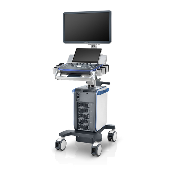
- Page 33 Introduction of Each Unit Name Function Monitor Displays the images and parameters during scanning. Touch screen panel Operator-system interface or control. Speaker Sound output. Ultrasound gel holder Used for placing the ultrasound gel. Used for placing the general probe (not including pencil probe Probe holder or intra-cavity probe).
- Page 34 Name Function Probe port Sockets connecting transducers and the main unit. Caster Used for securing or moving the system. Supports the monitor, for adjusting the height and position of Monitor supporting arm the monitor. Rear handle Used for pushing and moving the system. Supporting arm locking Used for locking/unlocking the supporting arm lever...
- Page 35 I/O Panel Symbol Function <1> USB ports. <2> HDMI High definition multimedia interface. <3> Network port. <4> VGA signal output. <5> S-Video Used for separate video output. <6> Audio signal output port, left channel. Audio signal output port, right channel. <7>...
- Page 36 Power Supply Panel Name Function <1> Power outlet Supplies power to optional peripheral devices. <2> Power inlet AC power inlet. Equipotential terminal Used for equipotential bonding which balances the protective earth <3> potentials between the system and other electrical equipment. 2-12 System Overview...
- Page 37 Physio Panel Name Function <1> USB port Connects USB device. <2> Pencil probe port Used for connecting a pencil probe. <3> MIC port Used for connecting a microphone. Connects to ECG leads to directly obtain the patient's ECG ECG lead signal input signals.
- Page 38 2.10 Control Panel English Name Description Power button <1> Press the button to turn on the system, the system enters the work status and the indicator becomes green. <2> Volume Adjust the volume. <3> <4> <5> Adjust the corresponding functions on the touch screen. <6>...
- Page 39 English Name Description <14> Text Enter/exit the textual comment status. <15> Clear Clear the comments or measurement caliper. Press to enter the Cine Review status from non-cine status when <16> Cine there is a multi-frame cine file playing. <17> Body Mark Enter/exit Body Mark.
- Page 40 English Name Description Confirm an operation. The function is same with the left-button of <40> the mouse. <41> Freeze Freeze/defreeze the image. <42> Save Save the image; user-defined key. <43> User-defined keys, functions of which can be defined in preset. <44>...
- Page 41 Function Jump to the next operable item. Back space Insert a space. Caps Lock Switch between upper/lowercase. Activate the Home function: return to start position of the Home comment. Activate the Home function, move the cursor to the target Set Home position, then press <Set Home>...
- Page 42 [Fn] key For these combination keys, press <Fn> + key to use the functions indicated with a frame on the key. No. Fn+ Name Function Move the cursor to the end of the row, or the rightmost side of an →...
- Page 43 2.11 Symbols This system uses the symbols listed in the following table. Their meanings are explained as follows: Symbol Description Type-BF applied part Caution AC (Alternating current) Functional grounding Equipotentiality Power button Foot switch Transducer sockets Pencil probe port Network port USB port Used for VGA output.
- Page 45 5. When using peripherals which are not powered by the ultrasound system's auxiliary output, or peripherals other than those permitted by Mindray, ensure the overall leakage current of peripherals and the ultrasound system meets the requirement of the local medical device electrical regulations (e.g., the enclosure leakage current should be...
- Page 46 Connecting the Power Cord & Protective Grounding This system can work when it is connected to the external power supply or the battery capacity is sufficient. NOTE: When the system is powered by the batteries, imaging modes including static 3D, STE, STQ, STIC and 4D continuous capturing, self-test, and DVR recording are not supported.
- Page 47 3.2.3 Equipotential terminal The symbol represents the equipotential terminal that is used for balancing the protective earth potentials between the system and other electrical equipment. 1. Be sure to connect the equipotential wire before inserting the power plug into the receptacle. Be sure to remove the power plug from the receptacle before disconnecting the WARNING: equipotential wire.
- Page 48 If the system begins to function improperly, immediately stop scanning. If the system continues to function improperly, fully shut down the system and contact the Mindray Customer Service Department or a sales representative. If you use the system in a persistent improperly functioning state, you may harm the patient or damage the equipment.
- Page 49 If you use a probe giving off excessive heat, it may burn the patient. WARNING: If you find anything not functioning properly, this may indicate that the system is defective. In this case, shut down the system immediately and contact Mindray Customer Service Department or sales representative. 3.2.5 Power the System OFF You must follow the correct procedures to power the system off.
- Page 50 3.2.6 Standby When the batteries are charged to full capacity, the system's standby time is no less than 24 hours. To enter standby: Open [Setup] → [System] → “General” to set the time for screensaver and standby. If the system is not carrying out an operation, the screensaver appears after the screensaver delay period.
- Page 51 Monitor Adjustment 3.3.1 Monitor Position Adjustment Gently hold the bottom edge of the monitor when adjusting its position. Height and displacement adjustment Move the monitor support arm up or down to adjust the height, back and forth to adjust the displacement NOTE: Take care not to trap your hands when adjusting the monitor up and down.
- Page 52 Lock the monitor If the ultrasound system is required to be moved within a short distance (for example: move to other department), turn the monitor to the horizontal level, push it to the locking structure, and then the monitor can be locked. For more details, please refer to the operation diagram that is attached to the supporting arm.
- Page 53 3. Hang the probe cable on the hanger located under the control panel to avoid excessive bending and damage. 4. Only use probes provided by Mindray. Aftermarket probes may result in damage or cause a fire. NOTE: If a probe port is not used for a long period of time, use the dustproof cover to protect the probe port from dust.
- Page 54 Lock NOTE: Before inserting the connector into the probe port, inspect the connector pin. If the pin is bent, do not use the probe until it has been inspected/repaired/replaced. 3.5.2 Disconnecting a probe 1. Turn the locking lever 90° counterclockwise to the vertical position. (Shown in the left figure) 2.
- Page 55 Function setting The function of the foot switch can be preset. For details, see “12.1.6 Key Configuration.” System Preparation 3-11...
- Page 56 USB port 1. Connect the data cable to the USB port on the ultrasound system. 2. Power the system and the printer on. 3. Install the printer driver. For details, please contact the Mindray service engineer. Print Both report and image can be printed on a graph / text printer.
- Page 57 (2) Click [Add Service] to enter the page. (3) Select the service type and enter the service name manually. (4) Click [OK] to return to the page. (5) Select the target printer from the drop-down list in the “Property” box and set other printing properties.
- Page 58 Uninstalling Press the clip in the direction of the arrow to get out the holder. 3-14 System Preparation...
- Page 59 System Preparation 3-15...
- Page 60 Basic Screen & Operation 3.8.1 Screen Display The screen displays ultrasound images, parameters, menus and measurement results windows. The following diagram maps out the different areas, such as patient information, image parameter & menu, image area, thumbnail of images saved, help information, soft menu, system status icon, etc.
- Page 61 Exam Mode Displays the currently used exam type, e.g. Abdomen. Probe Model Display the currently-used probe model, or the default model. Probe parameter area Displays the acoustic power. Including the acoustic power, MI (Mechanical Index) and TI (Thermal Index).
- Page 62 System status icon This area displays the relevant system icons, such as USB memory device, printer, network, Chinese/English entry, and current system time, etc. User-defined key and gesture function display region This area displays the function defined for those user-defined keys and gestures. For details about user-defined key, see “12.1.6 Key Configuration”.
- Page 63 Composition Description Functional When a screen's operation is complete, click the [OK] or [Cancel] button to save buttons or cancel the operation, and close the screen. To reposition a dialog box which is not a full-screen dialogue box: 1. Roll the trackball to move the cursor over the title bar of the dialog box. The cursor becomes a .
- Page 64 3.8.4 Touch Screen Operation Mapping mode Operating Operations region Swipe from this area to bottom to enter the mapping mode. Under mapping mode, swipe from this area to right to display the mapping menu. Under mapping mode, this area displays mapping menu, soft menu and tool bar, where you can adjust image parameters, perform measurement, image sending and review.
- Page 65 For detailed operations, see Chapter “5.1.2 Image Adjustment”. Touch or flip the menu to the left/right to adjust the image parameters; touch the measurement menu to select measurement tools and start measurement. Click any blank area on the touch screen to hide the mapping menu. See “5.1.2 Image Adjustment”...
- Page 66 Under mapping mode, open the saved image on the main screen, and touch the saved image on the touch screen (region 3), a toolbar will display on the top of the touch screen, you can perform review, send to, delete operations. Icon Description Enter review status, see “10.2.10.1 Review an Image”...
- Page 67 System Preparation 3-23...
- Page 69 Exam Preparation A patient exam can be started as per the following situations: New patient information: to start a new patient exam, patient information must first be entered. New exam: to start a new exam for patient who is already registered, the recorded information can be obtained through either iStation or Worklist.
- Page 70 4.1.1 New Patient Information The Patient Info screen is shown as follows: Place the cursor over the desired box. The field box is highlighted and a flashing cursor appears. Information can be entered or selected from the options. You can also change the cursor's position using <Tab>, <Enter> or the up/down controls. Information includes: 1.
- Page 71 2. Exam Type Exam application type You can select from: ABD (Abdomen), OB (Obstetrics), GYN (Gynecology), CARD (Cardiac), VAS (Vascular), URO (Urology), SMP (Small Part), PED (Pediatrics) and BREAST (Breast). Select the exam type tab to enter exam-specific information. ...
- Page 72 Exam Type Information Description Ectopic Times of abnormal pregnancy, e.g., extrauterine pregnancy Gestations Number of embryos (1, 2, 3, 4) Para Times of delivery. Abort Times of abortion. Height Weight Last menstrual period. Gravida Times of pregnancy. (Gynecology) Para Times of delivery. Times of abnormal pregnancy, e.g., extrauterine Ectopic pregnancy.
- Page 73 3. Operating Information Accession #: refers to the exam number used in DICOM. Diagnostician: person responsible for the exam. Operator: person responsible for image collection and scanning. Ref. Physician: person who requires the operator to carry out the ultrasound. Tip: If the name has been entered before, it is memorized by the system and can be selected from the drop-down list.
- Page 74 2. Select the data source Select the data source from the “Data Source” drop-down list. 3. Enter the search condition: Item: including Name, ID, DOB and Exam Date. Then enter a keyword in accordance with the Item selected. Select “Find in results.”...
- Page 75 Button Function Description Restore Exam Click to import the patient data from an external media. Click to send the selected patient data to an external device, Send Exams MedTouch/MedSight devices, DICOM storage server or printer. Activate Click to continue an exam that has been completed within 24 hours. Exams Resume Click to continue an exam that has been paused within 24 hours.
- Page 76 4.1.2.2 Worklist Worklist is an option. To use Worklist function, you have to configure DICOM Basic and DICOM Worklist options. When the DICOM basic package is configured and the Worklist server has been set, click [Worklist] in the Patient Info screen to query or import the patient data. (For details about the Worklist server setting, see the DICOM chapter.) Worklist can retrieve patient data of two kinds of protocols: DICOM and HL7.
- Page 77 b) Click [Transfer] and the patient information is imported into the [Patient Info] screen. After editing the patient information in the Patient Info screen, select [OK] to start a new exam. c) Click [Show Detail] to see details of patient data. (6) Click [Exit] to exit the Worklist.
- Page 78 Select Exam Mode and Probe If the exam mode is changed during a measurement, all measurement CAUTION: calipers on the image will be cleared. The general measurement data will be lost, but application measurement data will be stored in the reports. ...
- Page 79 Activate & Continue an Exam 4.4.1 Activate an Exam On the iStation screen, select an exam record which was completed within 24 hours and click [Activate Exam] from the menu which appears. Or click [Active Exam] on the iStation or Review screen to activate the exam.
- Page 81 Image Optimization The images displayed in this system are for reference WARNING: only. Mindray is not responsible for the correctness of diagnostic results. In Dual-B imaging mode, the measurement results of the merged image may be inaccurate. Therefore, the results are provided for reference only, not for confirming diagnoses.
- Page 82 4. Probes that can be switched to: select an appropriate probe for quick switch. 5. Recently used exam modes: select an appropriate exam mode for quick switch. Parameter magnitude setting: touch to increase/decrease the value. ON/OFF setting: some of the parameters can only be set to ON or OFF. ON activates the function, and when the function is activated the key is highlighted in green.
- Page 83 ON/OFF setting: some of the parameters only can be set at ON or OFF, ON is to activate the function, and when the function is activated, the menu item is highlighted in green. Functional item: touch to go to the corresponding function. ...
- Page 84 5.2.1 Basic Procedures for B Mode Imaging 1. Enter the patient information. Select an appropriate probe and exam mode. 2. Press <B> on the control panel to enter B mode. 3. Adjust the parameters to optimize the image. 4. Perform other operations (e.g., measurement and calculation) if necessary. ...
- Page 85 Depth Description This function is used to adjust the sampling depth, the real-time value of which is displayed in the image parameter area in the top-right corner of the screen. Operations Use the <Depth> deflector rod in the bottom-right part of the control panel to adjust the depth.
- Page 86 Imaging Adjustment Description More information can be obtained without moving the probe or changing the sampling position. FOV (Field of 1. To change the scan range, touch [FOV] on the touch screen to enter the FOV View) range and FOV position adjustment status. 2.
- Page 87 iClear Description The function is used to enhance the image profile so as to distinguish the image boundary for optimization. Operations Adjust using the [iClear] item or mapping-menu on the touch screen. The system provides 7 levels of iClear adjustment: off represents no iClear effect, and the bigger the value, the stronger the effect.
- Page 88 Effects Images can be optimized with less spot noise and higher resolution, so that more details for the structure are revealed. Impacts iBeam is not valid for phased probes. Image Merge Description In the Dual-split mode, when the images of the two windows have the same probe type, depth, invert status, rotation status and magnification factor, the system will merge the two images so as to extend the field of vision.
- Page 89 H Scale Description Display or hide the width scale (horizontal scale). The scale of the horizontal scale is the same as that of the vertical scale (depth). They change together in zoom mode, or when the number of the image window changes. When the image is turned up/down, the H Scale will also be inverted.
- Page 90 Ref. Line Description A reference line and a help line meeting the probe icon side 45° display on the 2D image under GYN and Pelvic Floor exam mode. This helps to locate midsagittal plane of pelvic floor precisely and define the reference line for measurement. Operation Tap [Ref.
- Page 91 5.3.3 M Mode Image Optimization Gain Description To adjust the gain of M mode image. The real-time gain value is displayed in the image parameter area in the top-right corner of the screen. Operations Rotate the <M> knob clockwise to increase the gain, and counter-clockwise to decrease it.
- Page 92 Edge Enhance Description This function is used to enhance the image profile so as to distinguish the image boundary for optimization. Operations Adjust using the [Edge Enhance] item or the mapping-menu item on the touch screen. There are 3 levels of edge enhance adjustment available: the bigger the value, the stronger the effect.
- Page 93 5.4.1 Basic Procedures for Color Mode Imaging 1. Select a high-quality image during B mode scanning, and adjust to position the area of interest in the center of the B mode image. 2. Press <Color> to enter B + Color mode. Roll the trackball to change the position and size of the Region of Interest (ROI) and press the <Set>...
- Page 94 ROI Adjustment Description This function adjusts the width and position of the ROI in Color mode. Operations When the ROI box is a dotted line, roll the trackball to change the size. When the ROI box is a solid line, roll the trackball to change the position. Press <Set>...
- Page 95 Line Density Description Line density determines the quality and information of the image. Operations Adjust using the [Line Density] item or the mapping-menu item on the touch screen. 4 levels of line density are provided: H, L, UH, M. Effects The higher the line density, the higher the resolution.
- Page 96 Scale Description This function is used to adjust the speed range of the color flow, which is adjusted using the PRF in the system. The real-time PRF value is displayed in the image parameter area in the top-right corner of the screen. Operations Rotate the knob under [Scale] on the touch screen or the mapping-menu item on the touch screen.
- Page 97 WF (Wall Filter) Description It filters out low-velocity signals to provide effective information, and this function is used to adjust the filtered frequency. The real-time value is displayed in the image parameter area in the top-right corner of the screen. Operations Select using the [WF] item or the mapping-menu item on the touch screen.
- Page 98 HR Flow (High Resolution Flow) Description This function enhances the micro vessel imaging effect, and can be used to analyze the tissue blood supply condition. Operations Touch [HR Flow] or the mapping-menu item on the touch screen to turn on HR Flow status (the [HR Flow] button is highlighted in green when the status is turned on.) The parameters in HR Flow mode are independent from those in Color mode.
- Page 99 During Power mode imaging, the image optimizing menus for B mode and Power mode are displayed on the touch screen at the same time. You can switch between the 2 modes by clicking the mode tabs. In Power mode, the acoustic power is synchronous with that of B mode. Adjustment of the depth to the B mode image will lead to corresponding changes in Power mode image.
- Page 100 PW/CW Doppler Mode PW (Pulsed Wave Doppler) mode or CW (Continuous Wave Doppler) mode is used to provide blood flow velocity and direction utilizing a real-time spectrum display. The horizontal axis represents time, while the vertical axis represents Doppler frequency shift. PW mode provides a function for examining flow at one specific site for its velocity, direction and features.
- Page 101 Meaning Frequency Gain Wall Filter SV Position Angle During PW/CW mode imaging, the image optimizing menus for B mode and PW/CW mode are displayed on the touch screen at the same time. If Color mode (Power mode) is also working, menus for certain modes will be displayed on the touch screen synchronously, and you can switch between them by clicking the mode tabs.
- Page 102 Operation Rotate the knob under [Img Qual.] item or the mapping-menu item on the touch screen to select the different frequency values. The adjusting range of frequency values can be divided into 3 levels: penetration preferred (Pen), general mode (Gen), and resolution preferred (Res). Select the frequency according to the detection depth and current tissue features.
- Page 103 Smooth To change the trace area, adjust through [Trace Smooth] item or the mapping-menu item on the touch screen. There are 4 levels of smooth effect provided, the bigger the value, the higher the smooth processing. Trace This function is used to set the sensitivity of tracing in the spectrum. Sensitivity To change the trace area, adjust through [Trace Sensitivity] item or the mapping-menu item on the touch screen.
- Page 104 Tint Map Description This function provides an imaging process based on color difference rather than gray distinction. Operations Adjust through the [Tint Map] item or the mapping-menu item on the touch screen to select the map. There are 8 color effect maps available. Gray Map Description This function applies the gray correction to obtain optimum images.
- Page 105 Operations Rotate the knob under [Baseline] or use the mapping-menu to adjust. Effects Changes the flow-velocity range to optimize the image. Angle Description This function is used to adjust the angle between Doppler vector and flow to make the velocity more accurate. The real-time adjusting angle value is displayed on the right part of the spectrum map.
- Page 106 Time Mark Description To show the time mark in M mode image. Operation Turn on or off the function through [Time Mark] item in the menu in the upper left corner of the screen. Effects When time mark is displayed on the PW mode image, it's much easier to identify the cardiac cycles and detect more details.
- Page 107 Or, set the position of the sampling line by moving the trackball. Press <Update>, then press <set> repeatedly and moving the trackball to adjust the position and size of the sampling gate. Press <Update> on the control panel to switch between the real-time mode and freeze mode. Anatomical M Mode Anatomical M Mode and Color Anatomical M mode images are provided CAUTION:...
- Page 108 Impacts When there is only one M-mark line on the screen, it cannot be hidden. Switching between the M-mark Lines Description To switch between the M-mark lines in Free Xros M mode. Operations Press <Set> to switch between the M-mark lines and press <Cursor> to show the cursor.
- Page 109 6. Define the next point using the trackball and <Set> key (touch [Undo] to cancel the current point and activate the preview point). The system updates the time-motion curve in real time. The sample line is displayed in green, and each point is marked with a number in sequence. 7.
- Page 110 In PW mode: after pressing the [TDI], press <PW> or <Update> to enter TVD Mode, TVD mode parameters will be displayed on the touch screen. In M mode: after pressing the [TDI], press <M> or <Update> to enter TVM Mode, TVM mode parameters will be displayed on the touch screen.
- Page 111 rate: is commonly used to evaluate how fast the tissue is deforming. TDI QA Workflow: 1. Perform image scanning on cardiac muscle, freeze the image and select a range of images for analysis, or select a desired cine loop from the stored images. Tip: ...
- Page 112 The X-axis represents the time (unit: s). Frame marker: a white line perpendicular to the X-axis which can be moved horizontally left to right (and right to left) by rolling the trackball. Click the checkbox beside the ROI to set whether to hide or display the QA curve. ...
- Page 113 Delete an ROI Press the <Clear> key to clear the last ROI. Touch [Delete All] on the touch screen to clear all ROIs. The corresponding traces for the deleted ROIs are erased from the plot. Press <Clear> to delete the last added ellipse ROI. ...
- Page 114 5.10.1 Overview Only probes DE11-3E and SD8-1E support Static 3D imaging. Ultrasound data based on three-dimensional imaging methods can be used to image any structure where a view cannot be achieved with the standard 2D-mode and to improve the understanding of complex structures.
- Page 115 ROI size and position Roll the trackball to change the ROI size and position. Press the <Set> key to toggle between setting the size (dotted line) and position (solid line). Curved VOI adjustment Roll the trackball to change the curved VOI position. Press the <Set> key to switch between the changing ROI and curved VOI states.
- Page 116 A window B window C window 3D window (VR) On the touch screen, the current window’s icon is highlighted, as shown below. Window A is the currently activated window. A, B and C sectional images correspond to the following sections of the 3D image. ...
- Page 117 Tip: the upper part of the 3D image in the 3D window corresponds to the orientation mark on the probe. If the fetal posture is head down (toward the mother’s feet), and the orientation mark is toward the mother’s head, then the fetus posture is head down in the 3D image. The 3D image can be rotated by touching [180°] on the touch screen to show the fetus head-up.
- Page 118 (3) Amniotic fluid (AF) isolation The desired region is adequately isolated by amniotic fluid. The region to be imaged is not obscured by limbs or umbilical cord. (4) The fetus keeps still. If there is fetal movement, it is necessary to rescan. ...
- Page 119 Draw a circle around the interested region, then the system will position the ROI to cover the region. You can adjust ROI size and position if necessary. Draw a circle here ROI cover this area Touch the cross cursor on the VOI curve and move the cursor with finger to adjust VOI curve. For setting the ROI, be sure to: ...
- Page 120 Press <B> or to enter B mode. 5.10.3.2 Static 3D Acquisition Preparation Description of parameters: Type Parameter Description Function: to set the range for imaging. Angle Range: 10-80°. Function: to adjust the image quality by changing the line density. Parameter Image quality can affect the imaging speed: the better the image adjusting Quality...
- Page 121 Activate MPR Touch [A], [B], [C] or [VR] to activate MPR or 3D image (VR). MPR Viewing In the actual display, different colors for the window box and the section line are used to identify the MPR A, B and C. ...
- Page 122 Asymmetric Touch on the touch screen to display MPR along with VR. A larger VR image along with 3 small MPR images will be displayed. View Direction The Region of Interest (ROI), also referred to as the Render Box in rendering, contains the section of the volume you want to render.
- Page 123 Touch [Up/Down], [Left/Right] or [Front/Back] on the second page of the touch screen to select the direction of the above Figure a, c and e. Touch [Flip] on the touch screen to view in the opposite direction to the current direction, as shown in Figures b, d and e.
- Page 124 Parameter Description Function: to adjust the transparency value for 3D image rendering. It implies the transparency of the light. The higher the value is, the tougher the surface becomes. Opacity Range: 0% to 100%. The lower the number is, the more transparent the gray scale information will be. Available only in Surface rendering mode.
- Page 125 Parameter Description Function: Superimpose the tint map basic on the VR image to improve the stereoscopic sensation and the contrast of the image. Depth VR Selection: Off, Black, Cyna, Blue, Rose Function: Improve the transparency in iLive rendering mode to observe the tissue, such as cyst.
- Page 126 Parameter Description The above five rendering methods can be applied to both gray and inversion modes. Where inversion means to invert the grayscale of the image, so as to enhance observation for low-echo regions, applicable for vessels, cysts, etc. When the function is turned on, the rendering mode parameters change to the corresponding inverse parameters.
- Page 127 NOTE: You can view the back of the VR by rotating it 180°. The back view image may not be as vivid as the front. (Here we call the initial view of the VR the “front”). It is recommended to re-capture rather than rotate the VR if a certain desired region is obscured in the VR.
- Page 128 Figure A Figure B Comments and Body Marks Function: Add comments and body marks to the MPR and VR. Operation: The operation is the same as adding comments and body marks in B image mode. 5-48 Image Optimization...
- Page 129 Image Editing Function Image editing is a more elaborate function than VOI adjusting for optimizing the 3D image by clipping (removing) the obscured part of the region of interest. Tip: In image editing status, no image parameters can be changed. A cutting cursor is displayed or an eraser cursor , and the system enters “Accept VOI”...
- Page 130 Type Parameters Description Polygon Allows you to trace a polygon on the image you want to cut. Line Use a multi-point line to trace the boundary quickly. As the eraser erases the image by means of sphere, you can adjust the size so as to adjust the erased area and depth.
- Page 131 6. Press <Freeze> on the control panel to freeze the image. Perform image cutting, rotation, annotation and image saving if necessary. For detailed operations, see “5.10.3.3 Static 3D Image Viewing.” 7. Exit 4D. Press <Update> to return to 4D image acquisition preparation, or, press <B>...
- Page 132 3. Press to enter the Smart 3D imaging preparation status, and define the ROI as well as the curved VOI. 4. Select a render mode. 5. Select an acquisition method, and set the corresponding parameters on the touch screen. Rocked mode: set [Angle] parameter. Linear mode: set [Distance] parameter.
- Page 133 Description of parameters: Parameter Description Function: select the image acquisition method. Selection: Rocked, Linear. Linear mode: during the sweep, the probe must be kept parallel. The scanning speed should be constant. Rocked mode: in this mode, the probe must be moved to a position where you can Method clearly see a middle cut of the object you want to scan and render.
- Page 134 5.10.5.4 Image Saving and Reviewing in Smart 3D Image saving In 3D viewing mode, press the single image Save key (Save Image to hard drive) to save the current image to the patient information management system in the set format and image size. ...
- Page 135 Diagnoses made only by assessing this 3D/4D acquisition are not WARNING: permitted. Every diagnostic finding must also be evaluated in 2D. NOTE: The user must ensure that none of the participating persons (mother, fetus, and user) move during the acquisition. Movement will lead to acquisition failure. If the user recognizes a movement during the scan, the acquisition must be canceled.
- Page 136 Acquisition Time The time required for a complete acquisition. Range: 7.5~17.5 secs. Angle The range from acquisition beginning to acquisition end. Range: 10~85°. 5.10.6.3 Color STIC 3D The system also supports the color STIC 3D flow image function. For details, see “5.10.10 Color 3D.”...
- Page 137 STIC/4D mode: freeze the system, and then roll the trackball to select the image. Static 3D: a frame of image is acquired after the acquisition is finished automatically. Multi-frame 3D images: acquire multiple 3D images in 4D imaging mode. 2.
- Page 138 <4> Central slice line (Current <5> Slice line <6> Space between two slice active slice) lines <7> Y-axis <8> X-axis <9> Slice position (to the central slice) <10> Slice order number <11> Central slice <12> Active slice be highlighted in mark green ...
- Page 139 Before After Image rotation Rotate <M>, <PW>, <C> to perform axial rotation or rotate <4D> knob to adjust the nearest VOI section (cut plane) position. For details, refer to descriptions in Static 3D. Image zooming Same as Static 3D image zooming. Image Optimization 5-59...
- Page 140 Hide/show reference image The system displays 3 standard sectional images (A plane, B plane, C plane) on the left side indicating the position of the slice lines; tap to hide the 3 reference images, and then slices are displayed on the whole image area. ...
- Page 141 7. Perform rotation and shifting operation to reference line. 8. Save images as necessary. 5.10.9.2 Operation Controls Current Quadrant Tap [A], [B] and [C] to select current active section image. Reset Click [All] in Reset field to reset parameters, orientation and zooming status. CMPR ...
- Page 142 Tap [Reset Curve] to cancel current drawing. Other Operations Single image zoom Press <3D> to view single SCV image. Zoom in Same as these in 3D/4D mode. Rotation Rotate <M>, <PW>, <C> to perform X/Y/Z rotation or rotate <4D> knob to adjust the nearest VOI section (cut plane) position.
- Page 143 Parameter Description Function: to set the transparency value for VR rendering. Opacity Range: 0%-100%. Function: to smooth the Color image and erase items by time averaging. Smooth Range: 0-10. Affects MPR as well as VR. Function: to adjust the mix percentage of grayscale information and color information.
- Page 144 5.10.11.2 Results Display After calculating, the following result will be displayed in the top-right part of the screen. Where L, W and H represent 3 diameter lengths of the fitting ellipsoid. V represents the calculated volume value. 5.10.11.3 Operation Controls Edit the VOI (Volume of Interest) Adjusting the VOI box size and position selects the volume data needed for calculation.
- Page 145 To Activate iLive 1. Enter 3D/4D image viewing status, or double-click the saved 3D/4D cine file in the iStation or Review screen. 2. Tap [iLive] on the touch screen to turn the function on, and adjust the parameters. Imaging using iLive 1.
- Page 146 small. As the level increases, the rendered image will become warmer but the details remain the same. Also, the shadow border will be smoother while the shadow area will be large Light source adjustment This function adjusts the position of the light source toward the VR image. Select the direction by touching the buttons under the “Light Position”...
- Page 147 Parameter Description Reset Classic/ IntPoint/ ExtPoint/ Reset the lighting mode to the original status. Parallel/ Torch/ 3-Light/ User 1/ User 2 Copy the lighting mode to customized lighting mode “User 1” or Copy to “User 2” Other Operations Zoom Same as in 3D/4D mode. Rotation Roll the trackball to view sectional images as necessary.
- Page 148 NOTE: To ensure the correctness of the results, please select an image with clear follicle boundary when entering smart FLC. 5.10.13.2 Operation Controls Edit ROI Same as the operation in ROI editing in Smart-V. Edit/ Undo Tap [Edit] on touch screen to turn on the editing function. It supports dividing, merging, adding and deleting of the follicle.
- Page 149 doctors find the sagittal view rapidly and is easy for doctors accessing the anatomical structure on sagittal view. (such as corpus callosum, cerebellar vermis, etc). NOTE: Smart Planes CNS is an option, which does not support Smart 3D mode. 5.10.14.1 Basic Procedures for Smart Planes CNS 1.
- Page 150 NOTE: To ensure the correctness of the result, please make sure the cerebral midline on the anatomical plane is displayed clearly and ROI enclose the whole cranial region. 5. Tap [Accept] to accept the edit to the MSP. The system recalculates the TCP, TTP and TVP according to MSP’s position.
- Page 151 Rotate [Font Size] knob to adjust the font size of the comment. See “9.1 Comments” for adding, moving or deleting the comments. Save the image. Click [Auto Comment] again to clean them. Axis Rotation Acquire 3D data. Tap [S-Planes CNS] to enter the automatic detection of the mode. Tap [TCP]/[TTP]/[TVP] to select the plane, and rotate <M>, <PW>...
- Page 152 Automatic Measurement There are 6 measurements: TCP supports the measurements on TCD, cerebral fossa pool; TTP supports the measurements on BPD, OFD, HC; TVP plane supports the measurement on LVW. Acquire 3D data. Tap [S-Planes CNS] to enter the automatic detection of the mode. Tap [Auto Measure] to show the caliper and the measurement number.
- Page 153 Acquire 3D data. Tap [S-Planes CNS] to enter the automatic detection of the mode. Reset the following operations: Tap [Current Plane] to reset the plane. The position of the current plane returns to the initial condition. The angle of the current plane returns to 0°. ...
- Page 154 5.11 Contrast Imaging 2D contrast imaging is used in conjunction with ultrasound contrast agents to enhance imaging of blood flow and microcirculation. Injected contrast agents re-emit incident acoustic energy at a harmonic frequency much more efficient than the surrounding tissue. Blood containing the contrast agent stands out brightly against a dark background of normal tissue.
- Page 155 5.11.2 Contrast Image Parameters 5.11.2.1 Parameter Area Display When entering contrast imaging mode, the screen displays the contrast image, and if [Dual Live] item on the touch screen is “ON”, both the contrast image (marked with “ ”) and tissue image (marked with “...
- Page 156 The time begins at 0. In live mode, there displays the elapsed time. For example, , it means the elapsed time is Freeze the image during the timing, the timer stops working, and there displays the elapsed time. For example, , it means the elapsed time between begin timing and freeze the image is 9s.
- Page 157 Long press the <iTouch> key to exit the function. 5.11.2.8 Image Saving Live capture In live mode, you can save the interested images by touching [Pro Capture] and [Retro Capture]. Cine saving In live mode, press the <Freeze> key on the control panel to enter cine review status. 5.11.3 Left Ventricular Opacification Basic Procedures for LVO: 1.
- Page 158 1. Perform image scanning, freeze the image and select a range of images for analysis; or select a desired cine loop from the stored images. Images from the current scan session (already in freeze mode) or from a saved image loop can be used.
- Page 159 Setting ROI This function is used for setting the target. Up to eight ROIs can be saved on the reference image, with the corresponding eight traces plotted simultaneously on the graph. Each ROI display has a different color, and its corresponding trace data is plotted using that same color.
- Page 160 3. Select [OK] to save the data and return to the QA Analysis screen. All displayed ROI traces are saved in the exported file. The parameters are included in the trace file if the user has fixed a ROI. ...
- Page 161 The system provides a color iScape function, so you can get more information from extended images. iScape imaging is an option. iScape panoramic imaging constructs an extended image from individual CAUTION: image frames. The quality of the resulting image is user-dependent and requires operator skill and additional practice to become fully proficient.
- Page 162 After the acquisition is completed, the panoramic image will be displayed and the system enters iScape viewing mode. Tip: During image acquisition, none of the parameters are adjustable, and functions such as measurement, comments and body marks are not available. ...
- Page 163 Color Map (in Power iScape) Rotate the knob under [Color Map] on the touch screen to select the map, as in Power mode. 5.12.3.2 Image Zooming Press <Zoom> button on the control panel to enter image zooming mode. Rotate the <Zoom> button to zoom in/out on the panoramic image.
- Page 164 In auto play mode, press/rotate the corresponding knob to change the play speed. When the speed is off, the system exits auto play mode. Review to a certain image. Press the knob under [Set Begin] to set the start point. Review to another image.
- Page 165 5.13.1.2 Enter/Exit Enter Select [Elasto][Strain E] on the touch screen to enter the mode. After entering the mode, the system displays two windows in real-time on the screen. The left one is the 2D image, and the right one is the Elasto image. ...
- Page 166 Map Position Description This feature is used to adjust the up/down position of the map. Operations Tap [Map Position] on the touch screen to adjust the parameter. Effects When the E Average function is enabled or disabled, the elasto curve is displayed based on different statistical amounts.
- Page 167 5.13.2.1 Basic Procedures for STE Imaging Select a proper probe. Perform 2D scan to locate the region. Tap [Elasto]→[STE] on the touch screen. Or press the user-defined key (set the user-defined key via [Preset]→[System]→[Key Config]) to enter the STE mode. Adjust the ROI based on the lesion size, and press <Set>...
- Page 168 Operation Rotate the knob under [Scale] on the touch screen. The value on the top of the Map changes as the Scale changes. The adjusting range: 0 to 29 in increment of 1. Impacts Parts which exceed maximum elasto modulus or shear wave velocity will be mapped onto the color on top of the color bar at top-left part of the image.
- Page 169 RLB Map Description Used to help the user judge the region where it is suitable for elasto measurements based on the distinctive colors in elasto image in quality map. The RLB Index shows the signal reliability of the STE inside the ROI, and it helps the user judge the effectiveness of the current elasto measurement.
- Page 170 iNatural Description This feature is used to optimize the review effect of multi-frame images to improve the stability between frames and provide a more continuous and smooth review effect of the multi-frame image. Operation Tap [iNatural] to enable the function and the button will be highlighted. Effects In auto cine review mode, the effect is more continuous and smooth.
- Page 171 Operation Rotate the knob under [Filter] on the touchpad. The higher the level is, the smaller the noise of the elasto image becomes, and the clearer the edge of the field target appears. Impacts The system restarts scanning B image and E image after the filtering is completed. Map Position Description This feature is used to adjust the up/down position of the map.
- Page 172 Or, click the cine to enter the cine review state. 5.13.3 STQ Imaging (Sound Touch Quantification) The STQ imaging is an option. The SC6-1E probe supports the STQ imaging in abdominal exam mode. The L12-3E, L9-3E, and L14-5WE probes support the STQ imaging in small organ (breast, thyroid, testes) and musculoskeletal exam modes.
- Page 173 Stress echo data are provided for reference only, not for confirming CAUTION: diagnoses. 5.14.1 Overview The Stress Echo feature allows you to capture and review cardiac loops for multiple-phase (multiple- stage) Stress Echo protocols. Stress Echo data consists of Stress Echo loops, wall motion scores, and all other information pertaining to the Stress Echo portion of a patient examination.
- Page 174 Saved Acquired loops phase/view Current stage/view Hints 3. According to the help information in the bottom of the screen, if an ROI is displayed, adjust the ROI size and position. Press <Update> key on the control panel to confirm the ROI. Tip: When you confirm the ROI size by pressing <Update>, you cannot adjust the ROI size during acquisition.
- Page 175 The Stage time is displayed to the right side of each stage in the protocol list, while the Exam time is displayed in the left side of the screen. Each saved image will be marked with two times T1 and T2. T1 refers to the total time of the whole acquisition, while T2 indicates the time the acquisition lasted for a certain stage.
- Page 176 Description of select mode controls: Mode Phase/view Cine selection controls Other controls Touch screen controls: Selection Description Stages: XX Rotate the corresponding knob under the button to select a stage. Views: XX Rotate the corresponding knob under the button to select a view. Acquire/ To switch the mode status.
- Page 177 Selection Description Text “On”/“Off” Function that turns the screen graphic text “On” or “Off.” The function is the same as the Labels on/off icon at the top of the screen. Information includes: name of level, name of view, heart rate, time stamp acquisition, timers, frame slider, loop ID, clip control.
- Page 178 The system inserts a red X into each selected box, like 3. Select [Display Selected] on the touch screen. The system displays the selected phases for each selected view side by side. To display all views for a specific phase: Select the phase label (for example, Rest).
- Page 179 Score Meaning Color Hypokinesis Yellow Severe Hypokinesis Khaki Akinesis Blue Dyskinesis Aneurysm Purple 2. Roll the trackball to select the value and then click the target segments, then the segment is assigned with a value. 3. Repeat step 2 to perform value assign for all segments. ...
- Page 180 Item Function Description Acquire mode Set the type of ROI: manual ROI or full-screen. Overlay Select the items to be labeled on each loop. WMS score type Set the chamber segment division method. To customize the length of systolic duration acquired for a specific heart rate. If “Trigger”...
- Page 181 Item Function Description View Set the views for each stage. Standard view Set the standard view. Load Import a protocol. Export Export a protocol. New protocol Create a new protocol. Copy protocol Create a new protocol with an existing one. Load Load an existing protocol.
- Page 182 5.14.7 Exiting the Stress Echo Feature To exit the Stress Echo feature: Press the <End Exam> key on the control panel or click [End SE exam] on the screen. 5.14.8 Measurement and Report Suspend the stress echo exam by selecting [Suspend Exam] on the soft menu. Press the measurement related keys or buttons to enter cardiology measurement.
- Page 183 4. Touch [Start Tracking] on the touch screen to start the tracking function. Adjust the parameters if necessary. Touch [Edit] on the touch screen to display the free cursor. Roll the trackball and press <Set> to re- select the trace reference points. Move the cursor to the exact boundary position and press <Set> again to set the right place.
- Page 184 Global strain. GS_rate Global strain rate. The system also displays the TPSD value on the Bull’s Eye graph: Time to Peak Standard Deviation (TPSD): Where the standardized value of time to peak data: (N is the number of time to peak data) Average standardized value of time to peak data: 4 - Display curve: Velocity/Displacement/Strain/Strain Rate.
- Page 185 5.15.4 Myocardial Boundary Tracing The system provides two kinds of tracing methods for two kinds of sections: Long axis section (A4C, A2C, ALAX): the 3-point method and manual tracing method are both available. 3-point method As shown in the following figure, after pressing <Set> to place 3 points clockwise on the image, the system generates the trace automatically.
- Page 186 [A4C]: apical four-chamber view. [A2C]: apical two-chamber view. [ALAX]: apical long axis view. [PSAX B]: short axis base view. [PSAX M]: short axis mid view. [PSAX AP]: short axis apex view. Parameter Adjustment [Thickness]: adjusts the tracing thickness, i.e., the distance between the endocardium wall and the tracking points on the epicardium.
- Page 187 “-” will display in the table to indicate those segments that are not well tracked. 5.15.7 Measurement/Comment In tissue tracking QA mode, only the Time measurement is available. For details, see the Operator’s Manual [Advanced Volume]. Comments and Body Mark operations are the same as in other modes. 5.15.8 Data Export The system provides a data exporting function, so that you can export calculation results for analysis (for instance, SPSS analysis).
- Page 188 proximal, R- Bladder posterior wall near uretha, V- Bladder posterior wall bottom, SP- Pubic symphysis. Following results are obtained: BSD (Bladder Neck – Symphyseal Distance), PVA (Pubovesical Angle), PUA (Pubourethral Angle), RVA (Retrovesical Angle), BND(Bladder Neck Descent), UTA (Urethral Tilt Angle), URA (Urethral Rotation Angle). Set Valsalva frame as described in step 2-3 and finish measurements.
- Page 189 Display & Cine Review Splitting Display The system supports dual-split and quad-split display format. However, only one window is active. Dual-split: press the key on the control panel to enter dual-split mode. Under Dual-split mode, press <Freeze> to freeze the image and then use to switch between the two images.
- Page 190 Tip: The size and position of the sample volume box change along with the scanning depth and area. 6.2.2 Pan zoom To use the function, use the knob on the control panel. 1. Rotate the <Zoom> knob to directly enter the pan zoom status. Or enter the touch screen mapping mode, and zoom the image by pinching the two fingers on the touch screen.
- Page 191 6.3.2 Imaging Display Format Switching When Frozen Image display format switching in freeze mode follows these principles: 2D+PW (press <Freeze> in 2D+PW imaging mode) If the imaging mode before freezing is 2D (frozen) + PW (real time) or 2D (real time) + PW (frozen), then in freeze mode, you can switch between 2D (frozen) + PW (activated) or 2D (activated) + PW (frozen) by pressing the <Update>...
- Page 192 6.4.2 Cine Review in 2D Mode (B/B+Color/B+Power/B+TVI/B+TEI) Manual Cine Review: After entering cine review in 2D mode, roll the trackball to review the cine images on the screen one by one. Or under touch screen mapping mode, touch the touch screen and swipe left and right to review the images.
- Page 193 e) In auto cine review, pressing the knob under [Auto Play] on the touch screen or rolling the trackball will stop the auto cine review and enter the manual cine review. f) Click [Jump to First]/[Jump to Last] to review the first or last image. Tip: you can perform cine review on each image window in the dual/quad splitting mode, and set the auto review region for each window.
- Page 194 Image Compare 6.5.1 Image Compare under Review Mode You can perform image compare through the path: Thumbnail area in the main screen; iStation screen (press <iStation> to enter); Review screen (press <Review> to enter). 1. In the above condition, press <Cursor> to show the cursor and click the target image file. 2.
- Page 195 2. In live mode or freeze mode, press the user-defined key for iCompare. 3. Select a single-frame image, multi-frame image, or screenshot in the iStation screen (press <iStation> to enter), Review screen (press <Review> to enter), or thumbnail area in the main screen.
- Page 196 Retrospective cine duration: set the time that user taps [Retro Capture] when playing the first frame of the image. It also refers to saving the cine or cycles retrospectively. Procedures: With the ECG disabled: tap [Cine] tab, and rotate [Time (Retro)] knob to adjust it. With the ECG enabled: tap [Cine] tab.
- Page 197 Physiological Signal A physiological input panel is available for this system. The physiological module consists of two channels: ECG and DC IN. DC IN is capable of handling external ECG signals from other ECG signal devices. The scanned image displayed is synchronized with the ECG traces. So ECG signals can be used as a time reference in an ultrasound exam (mainly in cardiology exams).
- Page 198 7.1.1 ECG Operation Basic Procedures 1. Connect the device. Turn off the system power supply, and connect the ECG cable to the ECG port on the physio panel of the machine. Turn on the system power supply. Place the ECG electrodes on the patient’s body (as shown in the following figures). Right Right Left...
- Page 199 Tips: The trigger mark is displayed in both freeze mode and live mode. The marks in Dual trigger are different in color. Trigger function is unavailable if the ECG trace is disappeared. Only the live 2D image can be triggered.
- Page 200 Respiratory Wave 7.2.1 Respiratory Wave Operation Basic Procedures 1. Connect the ECG lead and position the ECG electrodes. For details of ECG lead connection, see “7.1.1 ECG Operation Basic Procedures”. 2. Press <F12 Physio> on the control panel to enter Physio screen. 3.
- Page 201 Measurement You can perform measurements on zoomed images, cine reviewing images, real-time images or frozen images. For measurement details, see the [Advanced Volume]. Be sure to measure areas of interest from the most optimal WARNING: image plane to avoid misdiagnosis arising from inaccurate measurement values.
- Page 202 General Measurements 8.2.1 2D General Measurements 2D general measurements are general measurements on images in B, Color, Power or iScape imaging modes. The measurements listed below can be performed: Measurement Function Tools Distance Measures the distance between two points of interest. Measures the distance between the probe surface and the probing point Depth along the ultrasound beam.
- Page 203 Measurement Function Tools Measures the time of n (n≤8) cardiac cycles and calculates the heart rate in M mode images. Calculates the average velocity by measuring the distance and time Velocity between two points. 8.2.3 Doppler General Measurements Doppler general measurements are general measurements on PW/CW-mode images. The measurements listed below can be performed: Measurement Function...
- Page 204 Application Measurements Abdomen measurements - used for measuring abdominal organs (liver, gall bladder, pancreas and kidney, etc.) and large abdominal vessels. OB measurements - used for measuring fetal growth indices (including EFW) as well as GA and EDD calculations. The fetus can be evaluated through growth graph analysis and the fetal biophysical profile.
- Page 205 Measurement Accuracy Table 1 2D Image Measurements Parameter Range Error Distance Full Screen Within ±3% Trace Area Full Screen Within ±7% Circ Full Screen Within ±10% Angle Full Screen Within ±3% Volume Full Screen Within ±10 % Linear probes, convex probes, Full Screen Within ±5 % and phased...
- Page 206 Parameter Range Error Volume Section A/B/C Within ±20 % (not including Smart 3D mode) NOTE: Within the selected field range, measurement accuracy is ensured within the range mentioned above. The accuracy specifications are performed in the worst conditions, or based on real system tests, regardless of acoustic speed error. 8-6 Measurement...
- Page 207 Comments and Body Marks Comments Comments can be added to an ultrasound image to bring attention, notate or communicate information observed during the examination. You can add comments to: zoomed images, cine review images, real-time images, frozen images. You can type comments as characters, insert pre- defined comments from the comments library or insert arrow markers.
- Page 208 9.1.2 Touch Screen Display in Comments The system can be configured with comment text libraries including Abdomen, Cardiology, GYN (Gynecology), OB (Obstetrics), Urology, SMP (Small Part), Vascular, PED (Pediatric), Nerve Blocks and emergency medicine. In comments status, you can enter the comment text using the screen menu or touch screen.
- Page 209 Quickly select a comment in a group Configure groups to List 1, List 2, and List 3. For details about group configuration, please refer to "12.4 Comment Preset". Select a comment in a group by pressing or rotating the Knob under the [List 1], [List 2], or [List 3] button on the touch screen.
- Page 210 9.1.3 Adding Comments Typing comment characters 1. To set the comment location: Roll the trackball or press the direction keys on the keyboard to move the cursor to the desired comment location. 2. To type alphanumeric characters: You can enter characters using the keyboard. ...
- Page 211 Tracing (1) In comment status, touch [Trace] on the touch screen to activate the trace function. The current image is also displayed on the touch screen. (2) Control Panel operation: a) Roll the trackball to the desired position and press <Set> to confirm the start point. b) Roll the trackball to move the cursor along the edge of the desired region and trace the outline of the region.
- Page 212 9.1.6 Deleting Comments Deleting Comment Characters, Texts or Arrows 1. Move the cursor to the comment to be deleted. 2. Press the <Set> key to select the comment. 3. Press the <Back>, <Del.> or <Clear> key to delete the comment. Or, rotate the knob under [Grab/Del] on the touch screen to select the comment, then press the knob to delete the comment.
- Page 213 Library Rotate the knob under the [Library] button on the touch screen or press the knob to switch to the body mark library. Corresponding body marks are shown on the left. Page-turning If there is more than one page of body marks, rotate the knob under [Page] to turn the pages. ...
- Page 214 9.2.5 Body Mark Setting Returning to the preset or changing the exam/patient/mode/probe will clear the body marks. 9-8 Comments and Body Marks...
- Page 215 External storage media is recommended for archiving images. 2. The system's patient database space is limited. Back up or clear patient data regularly. 3. Mindray is not responsible for lost data if you DO NOT follow the recommended backup procedures. 10.1 Patient Information Management 10.1.1...
- Page 216 The system can save FRM files as BMP, JPG, TIFF, PNG or DCM files, or save CIN files as AVI or DCM files by Send To function in iStation screen. For details, please refer to “10.2.12 Sending Image Files” chapter. ...
- Page 217 The image thumbnail will appear in the thumbnail area on the bottom of the screen. When you move the cursor over the thumbnail, its filename and suffix will be displayed. You can set the clip saving length in the path: [Setup] → [System] → [General]. 10.2.5 Quickly Saving Full Screen Images to the System ...
- Page 218 1. Set the user-defined key through the path: [Setup]→ [System]→ [Key Config]. Select a key in the Key Function field on the left side and select “Save Image” in the Output page of Function field on the right side. 2. Click [New] in the middle part of the screen, then there will be “Function2: NULL” under the key function in the Key Function Field on the left side, and at the same time, “Output”...
- Page 219 To exit Review: Click [Exit] on the Review screen Press <ESC> or press <Review> again. Functions in the Review screen: Exam History: You can select more than one exams of one patient in iStation screen to check the patient exam history.
- Page 220 Other operations: [New Exam]: click to create a new exam for the selected patient and open the Patient Info screen. [Activate Exam]: activate the currently-selected exam (already ended) and enter the image scanning screen. [iStation]: click to enter the iStation screen. ...
- Page 221 10.2.11 iVision The iVision function is used to demonstrate the stored images. Image files are played one by one according to file names (including system-relevant and PC-compatible format images). To perform image demonstration: 1. Enter the iVision screen: Press the user-defined key for iVision (setting path: [Setup] → [System] → [Key Config]) 2.
- Page 222 [Add Catalog]: to add a catalog of files to the list. [Delete]: to delete selected files or catalogs from the file list. [Clear]: to clear all the files or catalogs in the file list. [Export]: to export selected directories/files to external storage devices. Click [Export] to bring up the Browse dialog box, select the path and click [OK].
- Page 223 For external memory devices (e.g., USB memory devices or DVD-RW) or iStorage: a) PC format transfer: JPG/AVI, BMP/AVI, TIFF/AVI, JPG/MP4, BMP/MP4, TIFF/MP4. Where a single-frame image is exported as JPG, TIFF or BMP, and the cine file is exported as AVI (windows), MP4(Mas OS). b) DCM format transfer: DCM (including single-frame DCM and multi-frame DCM).
- Page 224 Select the destination. Select whether to remove from local HD after Backup: if "Remove Exams" is selected, the patient information and images are removed; if "Remove Images" is selected, only the patient images are removed. Select whether to hide patient info: if "Default Info" is selected, the patient name is hide after backup;...
- Page 225 To export reports: (1) Check “Export Report” on the screen. (2) Select the report type to be exported. (3) Select whether to hide patient info: if "Default Info" is selected, the patient name is hide after backup; if "Custom Info" is selected, the system prompts a message requiring you to input the customed patient name, which will be displayed after backup.
- Page 226 10.4 iStation - Patient Data Management Patient data includes basic patient information, exam information, image files and reports. You can search, view, backup, send, restore or delete patient data in iStation. To Enter iStation Press the <iStation> key on the control panel, or ...
- Page 227 4. When you select a patient in the patient list, images of this patient will be displayed at the bottom of the screen. 10.4.3 Patient Data View & Management Select the desired patient information in the list. The following menu appears: ...
- Page 228 2. Select target: DICOM: send data or images to the storage server or send images to DICOM printer. DICOMDIR: back up data in DICOMDIR format; change the cine zoom mode, compression mode, and compression ratio. USB storage device or DVD-RW/DVD+RW drive: send exam to USB storage device or DVD-RW/DVD+RW drive.
- Page 229 (2) Click [Exit] to exit the Recycle Bin screen. NOTE: If there are more than 200 records in recycle bin, the system will ask you to clear the bin or not. Mindray recommends you clear the recycle bin regularly. Patient Data Management 10-15...
- Page 230 4. Select PC transfer format to send the report. 5. Click [OK] to start sending. To use iStorage function, you need UltraAssist software in 2.0 version (with V1.0 network protocol); consult Mindray service engineer for details. 10.6 Print 10.6.1 Print Setting For printer connection and driver installation, please refer to “3.7 Installing a Printer”...
- Page 231 2. Click the icon on the top right side of the image, and select the printer in the dialog box which appears. 3. Click [OK] to start printing. See the accompanying printer manuals for more details. 10.6.3 Report Printing Both reports and images can be printed on a graph/text printer. 1.
- Page 232 10.8 Patient Task Management Click in the bottom-right corner of the screen to bring up the following dialog box: The system supports following types of task management: Storage Task: displays the DICOM storage task. DICOM Print Task: displays the DICOM print task. ...
- Page 233 When the task management icon displays as , it means no task is underway or has failed. DICOM Service Setting On the Storage Task and DICOM Print Task page, click [Service Setting] to enter the DICOM service setting screen. For details, see the DICOM chapter. ...
- Page 234 2. Select the login type (Local or LDAP), and user name in the drop-down list. 3. Enter the password and click [Login]. To change users: 1. To log out the current user and change to another user, click in the bottom-right corner of the screen to bring up the following dialog box: 2.
- Page 235 1. Open the “Access Control” page using the path: [Setup] → [System] → [Access Control]. 2. Click [Add] to bring up the dialog box. 3. Enter the user name and password, confirm password, and select or deselect the check box from the privilege list.
- Page 236 2. Select a user, click [Edit Privilege] to enter the "Edit user privilege" dialog box, and select or deselect the check box from the privilege list. 3. Click [OK] to confirm the editing and exit the dialog box. The edited privileges will appear in the User List.
- Page 237 4. Click [OK] to exit. Configuring password policy Turn on the access control function and log in to the system as Administrator before you configure the password policy. Open the “Access Control” page using the path: [Setup] → [System] → [Access Control]. Click [Password Policy Config]: Parameter Description...
- Page 238 Parameter Description Remark user inputs the wrong password for 5 times within 60 minutes, the account is locked, and the user can log in to Lockout Set the duration after an account is locked. the system only after Duration 60 minutes. Other users with unlocked accounts can still log in to the system normally.
- Page 239 Set the automatic machine locking time in the drop-down list beside "Auto Lock Machine". Click [Save] to exit. The system automatically locks the machine after exceeding the set time. In this case, you can unlock the current account or change users. 10.9.5 LDAP Privilege Management Turn on the access control function and log in to the system as Administrator before you edit privileges for the LDAP (Lightweight Directory Access Protocol) users.
- Page 240 Parameter Description Set days to keep the cached passwords in the local system Users can log in to the server even without accessing the network within the setting days. Days to keep cached Empty: the passwords are kept in the password local system permanently.
- Page 241 User field name 1. Enter [Setup] → [System] → [Access Control] → [LDAP Config]. 2. Select [Use user field name] to customize the user field name. After that, the members and privileges cannot be edited. 3. Enter the user field name in the field box of the "User field name" (the user field names are configured in the LDAP server.
- Page 242 4. Enter the IP address and click [OK]. 5. Log on with the server account and password. 6. Check the data transferred and carry out operations as necessary. 10-28 Patient Data Management...
- Page 243 DICOM/HL7 NOTE: Before using DICOM, read the DICOM CONFORMANCE STATEMENT electronic file provided with the device. The chapter is restricted to the preset, connection verification and DICOM services of the DICOM- configured ultrasound machine, and does not include SCP configurations such as PACS/RIS/HIS. The DICOM package is optional.
- Page 244 11.1 DICOM Preset 11.1.1 IP Preset See “Appendix D Wireless LAN” for details. 11.1.2 DICOM Local Preset 1. Enter the DICOM local preset screen using the path: [Setup] → [DICOM/HL7]. 2. Enter AE Title, Port and PDU according to the actual situation, then click [Save] to exit the screen.
- Page 245 Name Description You can ping other machines after entering the correct IP address. Ping You can also select a server in the Device list to ping it. Device List Displays the added device. Set DICOM Provides server settings of DICOM service. For details, see the following Service chapters.
- Page 246 Tip: The AE Title should be the same as the SCU AE Title preset in the server (PACS/RIS/HIS). For example, if the AE Title of the server preset in the storage server is Storage, and the AE Title of the accepted SCU is preset as Machine, then in the figure above, the AE Title of Local should be Machine, and the AE Title of the storage server should be Storage.
- Page 247 DICOM storage preset items are described as follows: Name Description After setting the servers in the DICOM Preset screen, the Device names will appear in the drop-down list. Select the name of the storage server. Service Name The default is xxx-Storage, user-changeable. Application Entity title.
- Page 248 Name Description Select the color mode. If you choose the mixed or the grey, RLE/JPEG is unavailable. The image uses 24 bit when sending the image from the Color Mode ultrasound device to the server; it depends on the image when choosing the mixed.
- Page 249 Images of PW/M/TVM/TVD mode (B image is not frozen) and images other than PW/M/TVM/TVD mode: if “Max Frame rate” is not “Full” and the actual frame rate is larger than the set value, the system will save the image files in a frame rate of the set value, and transfer in a frame rate of B mode.
- Page 250 Name Description Set the maximum retries (0-9). The default value is 3. If the Maximum Retries DICOM task sending to the server fails, the retry times should be 3. Interval Time(Sec) Interval time for the system to retry a connection. Timeout(Sec) Refers to timeout during association establishment.
- Page 251 Name Description List Select an item in the service list. Click [Default] and you will see Default “Y” in the Default column. Click to verify that the two DICOM application entities are Verify properly connected. 11.1.3.3 DICOM Worklist Preset 1. On the DICOM Service screen, click the [Worklist] page tab to enter the Worklist page. 2.
- Page 252 11.1.3.7 HL7Query Preset HL7 protocol, enacted by Health Level Seven organization in 1987, is a 7 layer (application layer) based on the OSI model (Open System Interconnection) released by ISO (International Standard Organization).HL7 is used to rule and manage communications between HIS/RIS system and devices, as well as reduce the intercommunication cost.
- Page 253 Type Item NOTE Set the image quality of unloaded AVI. The system unloads according to the settings. Image quality The higher the image quality is, the clearer the unloaded image is. The unloading speed become slower with the larger space. AVI encode Set the unloading format of the AVI.
- Page 254 Send images on iStation/Review/main screens (1) Select images Press <iStation> on the control panel to open the iStation screen. Click to select a patient or an exam record in the list. Thumbnails are displayed in the thumbnail area in the lower part of the screen, then click to select a thumbnail or several thumbnails.
- Page 255 c) Click [Exit] to exit the page and return to the Setup menu, then click [Save] on the Setup menu to make the preset take effect. (3) After finishing the presets, perform image scanning. Each time <End Exam> is pressed on the control panel, the system will send the image to the default DICOM storage server for storage.
- Page 256 b) Click [Print] to open the Print page. c) Select a Print server in the Service List and click [Default]. You will see “Y” marked in the Default column. d) Click [Exit] to exit the page and return to the Setup menu, then click [Save] on the Setup menu to make the preset take effect.
- Page 257 3. After finishing the presets, perform image scanning. Each time <End Exam> is pressed on the control panel, the system will send the image to the default DICOM storage server for storage and send storage commitment to the storage commitment server. If images are successfully sent to the storage server, the storage commitment server will return information about the successful image storage.
- Page 258 3. Click [Query], the system performs the query and lists out the results into the patient (source) list. You can perform further query basing on the results by entering new query information. 4. Select one or more patient records according to the actual situation. Click [Select All] to select all the patient records in the list.
- Page 259 1. Connect the external media containing DCM files to the system. 2. In iStation, review the data stored on the external media. 3. Select the data to be restored in iStation. 4. Click on the iStation screen. NOTE: Only system-accessible media can be selected. 11.5 Structured Report DICOM OB/GYN Structured reports, Cardiac Structured reports, Vascular Structured reports, Breast Structured reports, and Abdomen Structured reports are supported by this system.
- Page 260 11.7 DICOM Task Management DICOM Task Management is used for viewing task progress or managing tasks after sending images for storage, printing or media storage. For details, see “10.8 Patient Task Management.” 11-18 DICOM/HL7...
- Page 261 CD/DVD or USB memory device. When the preset data is changed, be sure to save the preset data CAUTION: according to the methods described in this chapter. Mindray is not responsible for the loss of preset data. ...
- Page 262 12.1 System Preset The system automatically enters the [System] screen after you enter Setup. Page Description To set the hospital name, language, time zone, time format and system Region date/time. General To set patient information, exam setup, system dormancy, display and so on. Image To set general parameters in imaging modes.
- Page 263 12.1.1 Region Open the Region page via [Setup] → [System] → [Region]. Item Description To set the hospital-relevant information such as name, Hospital Information address, telephone, and so on. Language To select a language (input) for the system. Import image for logo loading. NOTE: For a better display effect, please try to use an Load Logo image with 400*400 pixels.
- Page 264 12.1.2 General Open the page via [Setup] → [System] → [General]. Type Item Description Patient Banner Display To select if to display the available patient information Content items on the screen. H&W Unit To set the unit for patient height and weight. Patient Info Surface Formula To set the surface formula.
- Page 265 Item Description Select the different saver methods to the system. After enabling the screen saver, check “Mindray” to select the image from the system. Or click [Browse] to select the image on your own. Click [Preview] to preview the screen saver image.
- Page 266 Type Item Description To set the steer mode in B+ Color +PW/CW imaging mode. C&(PW/CW): select to adjust the sample volume in color mode and sample line in PW or CW mode Steer together. C/(PW/CW): select to adjust the sample volume in color mode and sample line in PW or CW mode individually.
- Page 267 Key function setting You can set the functions for <Save>, <Print>, user-defined keys (including F3, F4, F5, F6, F12 and P) and two-finger gesture. See “3.8.4 Touch Screen Operation” for details about two- finger gesture operation. To assign a function to a key: a) Click to select the desired key in the Key Function column on the left side of the page.
- Page 268 12.1.8 Output Type Item NOTE Set the image quality of unloaded AVI. The system unloads according to the settings. Image quality The higher the image quality is, the clearer the unloaded image is. The unloading speed become slower with the larger space.
- Page 269 You can assign available exam modes for probes. 1. To select a probe, move the cursor over the Probe column and select the probe model using the drop-down list. 2. Select/delete exam modes: On the left side, you can view all the available exam modes in the exam library for the probe. On the right side of the screen, you can view the current exam modes assigned to the probe.
- Page 270 1. Add comments: directly enter user-defined comment texts, or select available items (select comment texts for the comment library or select comment in groups). Directly enter user-defined comment texts: posit the cursor in the field box above [Add Comment], enter the text comment through the keyboard, and then click [Add Comment]. Then the directly-entered comment will be added to the Available Items and Selected Items.
- Page 271 1. Add groups: posit the cursor in the field box near [Lists Name], enter the group name through the keyboard, and then click [Add Group]. Then the entered group will be added to the Group Lists. 2. Rename groups: select a user-defined group, enter the group name through the keyboard, and then click [Rename].
- Page 272 12.8 Print Preset This screen is used to set up the printer and image printing. Click [Print] in the preset menu to enter. Printer setting The printer settings include print service and print driver. Print Service Setting Add Service: click to begin adding print services.
- Page 273 12.9 Network Preset Parameters for transferring are set here. For details of local IP setting, see “Appendix D Wireless LAN”. 12.9.1 iStorage Preset You can send exam data or images to the iStorage server and perform analysis using UltraAssist. For details about this feature, see the UltraAssist manual. ...
- Page 274 Transmission Encryption After accessing the network, click [VPN Config] to enter the "VPN Config" interface. Parameter Description No driver: click [SetupDriver] to enter the "TAP- Windows 9.21.2 Setup" interface, and do as instructed. Ready: the VPN is ready for use. Status Advance: VPN Advance Configuration Connected: VPN is successfully connected.
- Page 275 Parameter Description Hide characters The password is displayed as *. Connect/ Disconnect Connect or disconnect VPN. Enters the "VPN Advance Config" interface. Advance Reset: if the system does not respond after you click [Config], click [Reset]. Config: enters the "OpenConnect-GUI VPN client" interface.
- Page 276 Select [Upload logs to remote server] to upload logs to the remote server, Mindray service engineers can acquire and handle those log. Check the process in “task management” page, please refer to 10.8 Patient Task Management. 12.10 Maintenance In the Setup menu, select [Maintenance] to enter the screen.
- Page 277 Procedures: 1. Select the target module. 2. Click [Export] to open the [Export All Data] screen. 3. Select the path to save the data. 4. Select the exported file and type as PDP and click [OK]. 12.10.3 Importing Setup Data This function is used to import the existing setup data to the setup data memory of the system.
- Page 278 12.10.5 Other Settings Item Description Export Log Export the log. Self Test Perform system self-test and restart the machine. Recover the ultrasound system (including Operating System and Recover Doppler). For this function, you need a one-time password, please contact the Setup Enter Windows service engineer or your agent.
- Page 279 Windows Defender is already installed on the system. The McAfee software is an option. If the McAfee software is installed, the system displays "McAfee is running". If you want to buy McAfee, contact Mindray representatives. Notes: McAfee cannot be uninstalled after successful installation.
- Page 280 12.12 System Information Click [About] on the Setup menu to enter the system information screen. This screen displays the system software version, WLAN module FCC version and versions of other modules. You cannot edit the information, only view them. The information varies depending on the system configurations and version.
- Page 281 Probes and Biopsy 13.1 Probes The system supports the following probes: C11-3E P7-3E L12-3E SP5-1E L9-3E DE11-3E SC6-1E V11-3HE Probes and Biopsy 13-1...
- Page 282 L20-5E SD8-1E L14-5WE SC5-1NE For details about the TEE probe, please refer to the TEE Ultrasonic Transducer manual. 13-2 Probes and Biopsy...
- Page 283 13.1.1 Probe Functions by Part The basic structures and corresponding functions of probes are basically the same. Take the following probe as an example. <2> <1> <3> <4> <5> Name Function <1> Probe head Converts the electrical signal to an ultrasonic signal, focusing the sound beams in a given direction while it receives the reflected ultrasonic signal and converts it to an electrical signal for transmission over the cable.
- Page 284 13.1.2 Orientation of the Ultrasound Image and the Probe Head The orientation of the ultrasound image and the probe are shown below. The “Mark” side of the ultrasound image on the monitor corresponds to the mark side of the probe. Check the orientation prior to the examination (using a linear probe as an example).
- Page 285 Operating procedures (with biopsy function): Inspection before examination Connection to the ultrasonic diagnostic system Examinations Biopsy procedure Disconnection to the ultrasonic diagnostic system Thoroughly cleaning the needle-guided bracket Wiping off the ultrasound gel Sterilization of the needle- guided bracket Thoroughly cleaning the transducer Inspection after use Drying the transducer Storage...
- Page 286 Operating procedures (with no biopsy function): Inspection before examination Connection to the ultrasonic diagnostic system Examinations Disconnection to the ultrasonic diagnostic system Wiping off the ultrasound gel Thoroughly cleaning the transducer Drying the transducer Disinfecting the transducer Rinsing the transducer Drying the transducer Inspection after use Storage...
- Page 287 13.1.4 Wearing the Probe Sheath A legally-marketed probe sheath must be installed over the probe before performing intra-cavitary and intra-operative examinations. Protective barriers may be required to minimize disease transmission. Probe sheaths are available for use in all clinical situations where infection is a concern.
- Page 288 Model Length(mm) Width(mm) Height(mm) Cable Length(mm) C11-3E 1950±50 L12-3E 1950±50 P7-3E 1950±50 SP5-1E 2200±50 L9-3E 1950±50 V11-3HE 1950±50 SC6-1E 109.5 76.7 1950±50 SD8-1E 77.6 2260±50 L14-5WE 66.4 25.5 1950±50 L20-5E 24.1 1950±50 DE11-3E 323.6 46.7 1950±50 SC5-1NE 109.5 76.7 1950±50 The above is a dimension illustration of the V11-3Ws probe.
- Page 289 No cleaning and disinfecting may result in the probe becoming CAUTION: a source of infection. Please follow the disinfectant manufacturer's manual for performing cleaning and disinfection, including preparing sterile water and cleaning and disinfection time. NOTE: 1. After the examination, wipe off the ultrasound gel thoroughly. Otherwise, the ultrasound gel may solidify and degrade the image quality of the transducer.
- Page 290 10. Check whether the probe has defects such as peeling, rifts, bumps, cracks, or liquid spill. If such defects exist, the probe has reached the end of its service life. In this case, stop using it and contact the Mindray service department. Low-level disinfection of a non-critical probe Use protective eyewear when disinfecting using sprays.
- Page 291 In this case, stop using it and contact the Mindray service department. Store the probe in a cool, clean and dry environment. And repeat the cleaning and disinfection process before the next use.
- Page 292 Strain relief Probe handle NOTE: Observe the graph here carefully to immerse the transducer. Only soak parts of the transducer below the strain relief. Compatible Disinfectants High-level disinfectant 510K No. Name Region K030004 Cidex OPA Solution The USA & Canadian (TM) K924434 Cidex...
- Page 293 Low-level disinfectant Name Registration No. 9480-6 SANI-CLOTH PLUS GERMICIDAL DISPOSABLE CLOTH 70627-56 OXIVIR TB 9480-9 PDI Sani-Cloth AF3 Germicidal Disposable Wipe 46781-8 CAVIWIPES 46781-6 CAVICIDE 13.1.6 Environment Working condition Use the probes in the following ambient conditions: Ambient Atmospheric Relative humidity Probe temperature pressure...
- Page 294 Excessive vibration Heat generators 2. When the probe is sent to the MINDRAY Customer Service Department or a sales representative for repair, be sure to disinfect it and keep it in the carrying case to prevent infection. 3. Sterilize the carrying case as necessary.
- Page 295 If an abnormality is found on the needle-guided bracket, immediately stop using it and contact the MINDRAY Customer Service Department or a sales representative. DO NOT use a needle-guided bracket while scanning is performed.
- Page 296 When performing biopsy procedures, only use sterile ultrasound gel that is certified as safe and manage the ultrasound gel properly to ensure that it does not become a source of infection. When performing an operation involving biopsy, wear sterile gloves. Image of the biopsy target and the actual position of the biopsy needle: Diagnostic ultrasound systems produce tomographic...
- Page 297 Dispersion of the ultrasound beam Probe Needle Target Ultrasound beam The biopsy needle may not have actually entered the target object even though it appears to have done so in the image. To avoid this, note the points below: Do not rely only on the needle tip in the image.
- Page 298 Needle-guided brackets are available for purchase as optional accessories and are used in combination with the probe. Some probes have corresponding needle-guided brackets and needles. To order needle-guided brackets, contact the MINDRAY Customer Service Department or a sales representative. For biopsy or treatment, ultrasound-guided biopsy procedures can be performed using the probe together with a needle-guided bracket (optional accessory) and a biopsy needle (provided by the user).
- Page 299 Probes and Biopsy 13-19...
- Page 300 Plastic/needle detachable needle-guided bracket: Name Description Support for needle- <1> Used for installing the needle-guided bracket on the probe. guided bracket Used for determining the angle of the biopsy. There are three <2> Angle block angle block specifications. Used for installing biopsy needles. There are five guiding block <3>...
- Page 301 NGB-011 Needle guide Needle guide clamping knob Locating pit Clamp Needle guide hole Locating groove Grip knob Needle guide rack Needle-guided bracket Probe NGB-018 Needle guide hole Guiding block Guiding block specification Pinch nut of bracket Angle shift sign Angle pinch nut Angle-adjusting base Angle block...
- Page 302 NGB-022 Needle fixing nut Groove Lock pin Clamp Needle type dial scale Angle adjusting base Angle fixing nut Needle guide hole NGB-025 Location Front clamp clamp Upper clamp Front Pinch nut slot Intra-cavity prob Upper clamp Lower Location clamp hole 13-22 Probes and Biopsy...
- Page 303 NGB-027 Position block Upper clamp Front clamp Pinch nut Intra-cavity probe Front slot Lower clamp Positioning block NGB-034 Needle guide hole Lock pin V-shaped Clamp V-shape cover guiding block Needle fixing Needle adjusting base Needle type dial scale Guiding groove Angle fixing Angle adjusting...
- Page 304 NGB-035 NGB-039 13-24 Probes and Biopsy...
- Page 305 Note: the above needle-guided brackets whose name starts with NGB are reusable. The CIVCO brackets are disposable. 13.2.2 Basic Procedures for Biopsy Guiding 1. Select the correct needle-guided bracket and needle and install them properly. For details, see “13.2.3 Needle-Guided Bracket Inspection and Installation.” 2.
- Page 306 13.2.3.1 Inspection of the Needle-Guided Bracket Be sure to perform inspections before and after using the needle-guided bracket. If an abnormality is found on the needle-guided bracket, immediately stop using it and contact the MINDRAY Customer Service Department or a sales representative.
- Page 307 Plastic needle-guided bracket: (1) Put the sterile probe sheath on. (2) Hold the probe in one hand, select the correct needle-guided bracket and hold it with the other hand. Align the tab at the narrow end of the needle-guided bracket with the groove of the probe, then push the needle-guided bracket forward, so the tabs and grooves of the needle-guided bracket align with the grooves and tabs of the probe.
- Page 308 NGB-018 (1) Put the sterile probe sheath on. (2) Select a suitable needle-guided bracket and match the groove to the tab of the transducer. Mount the bracket onto the transducer. The needle-guided brackets may be different from each other, but the methods are the same. (3) Screw the pinch nut of the needle-guided bracket to ensure that the needle-guided bracket is properly installed on the transducer.
- Page 309 Align front clamp with front groove Push the bispy forward (arrow’s direction) until the locating pole inserting into the location hole. Turn the lower clamp againsy the intra-cavity probe. Tighten the nut to lock the biopsy (arrow’s direction). Insert the locating pole into the locating hole ...
- Page 310 Tighten the pinch nut of the needle-guided bracket to confirm that the needle-guided bracket is properly installed on the transducer. Adjust the dial scale to the required needle type shift. Adjust the needle angle to the proper shift as required (loosen the nut first, and then tighten the nut based on the shift you need).
- Page 311 NGB-035 (1) Put the sterile sheath on the probe. (2) Select a proper needle-guided bracket, and match the locating groove with the tab of the transducer. Mount the bracket onto the transducer. (3) Tighten the pinch nut of the needle-guided bracket to confirm that the needle-guided bracket is properly installed on the probe.
- Page 312 (5) Insert the needle into V-shaped guided block. (6) Release the pressing block, adjust the angle adjusting nut to confirm that the needle can freely slide in a vertical direction. NGB-039 (1) Put the sterile sheath on the probe. (2) Select a proper needle-guided bracket, and match the locating groove with the tab of the transducer.
- Page 313 (4) Hold the probe and press the pressing block to separate V-shaped guiding block from the pressing block. (5) Insert the needle into V-shaped guided block. (6) Release the pressing block, adjust the angle adjusting nut to confirm that the needle can freely slide in a vertical direction.
- Page 314 Select the Needle Select the proper needle according to the specification above, and adjust the needle shift to the same specification of the selected needle. Ensure that all guide parts are properly fixed prior to performing a CAUTION: biopsy. 13.2.4 Biopsy Menu/Guideline Verification Adjusting the needle mark is necessary before each biopsy procedure.
- Page 315 The guide line is a dotted line which consists of three kinds of dots. The distance between two dots is depth-dependent. Move the cursor over the big dot and a numeral, representing the biopsy depth, is displayed. The biopsy guidezone adjusts along with image adjustments, such as image inversion/rotations, zoom and depth changes.
- Page 316 (2) Separate the residual part of the needle-guide bracket and the transducer from the needle. (3) Loosen the bracket's pinch nut and remove the needle-guided bracket from the transducer. NGB-022 (1) Pull the lock pin and open up the V-shaped cover to expose the needle. (2) Separate the bracket and the transducer from the needle.
- Page 317 Turn over the V-shaped cover to expose the needle. Remove the probe and bracket. Separate Screw the pinch nut to release the needle-guided bracket. NGB-035 (1) Hold the probe and press the pressing block to separate V-shaped guiding block from the pressing block.
- Page 318 (2) Remove the needle. (3) Rotate the clamping nut to separate the bracket from the probe. NGB-039 (1) Hold the probe and press the pressing block to separate V-shaped guiding block from the pressing block. (2) Remove the needle. (3) Rotate the clamping nut to separate the bracket from the probe.
- Page 319 13.2.6 iNeedle (Needle Visualization Enhancement) During a biopsy, the metal needle attached to the probe pierces the tissue at a certain angle. Due to the needle's acoustic impedance, the ultrasonic beam cannot penetrate the metal needle and a reflecting boundary is formed. As in Figure 1, if the deflection angle is very large, the needle display is not clear.
- Page 320 Needle Direction Description This function adjusts the biopsy needle direction according to actual direction of needle insertion. The iNeedle region changes correspondingly. Operation Rotate the knob under the [Needle Dir.] item on the touch screen to select the direction, which can be left or right. B/iNeedle Description This function is used to display the B image and iNeedle image synchronously.
- Page 321 1. Wear a pair of gloves to prevent infection. 2. Clean thoroughly in accordance with the cleaning procedure before sterilization. 3. Sterilize the needle-guided bracket by using an appropriate sterilant. MINDRAY recommended the following solution to sterilize the needle-guided bracket. For how to use a sterilant, see the operator's manual provided by the manufacturer.
- Page 322 2. Between examinations, keep the needle-guided bracket in a sterile environment. 3. If the needle-guided bracket is sent to your MINDRAY representative for repair, be sure to disinfect or sterilize it and keep it in the carrying case to prevent infection.
- Page 323 13.2.9 Disposal Be sure to sterilize the needle-guided bracket before disposing of it. Contact your MINDRAY representative when disposing of this device. 13.3 Middle Line Middle Line helps to locate and observe the focus point of lithotripsy wave during lithotripsy treatment.
- Page 325 Accidental exposure to strong electromagnetic fields may result in image and data loss, so check if the recording is successful as soon as possible. Mindray is not responsible for any data loss.
- Page 326 14.3 DVR Video Replay You can replay the video and audio record. Replay on PC Connect the USB disk or optical disk with the file to the PC, open the file directly. Replay on the ultrasound system 1. Click to open the dialogue box and select desired playing type: Hard disk/USB/CDROM;...
- Page 327 Acoustic Output This section of the operator’s manual applies to the overall system, including the main unit, probes, accessories and peripherals. This section contains important safety information for device operators pertaining to acoustic output and how to control patient exposure through use of the ALARA (as low as reasonably achievable) principle.
- Page 328 15.4 MI/TI Explanation 15.4.1 Basic Knowledge of MI and TI Mechanical Bioeffect and Thermal Bioeffect The relationship of various ultrasound output parameters (frequency, acoustic pressure and intensity, etc.) to bioeffects is not fully understood at present. It is recognized that two fundamental mechanisms may induce bioeffects.
- Page 329 15.4.2 MI/TI Display TI and MI values are displayed in the top part of the screen in real time. The operator should monitor these index values during examinations and ensure that exposure time and output values are maintained at the minimum amounts required for effective diagnosis. NOTE: If a value of MI or TI exceeds 1.0, the ALARA principle must be practiced.
- Page 330 15.6 Acoustic Power Control A qualified operator may use the system controls to limit the ultrasound output and to adjust the quality of the images. There are three categories of system controls relating to output. They are: Controls that have direct effect on the output ...
- Page 331 15.7.2 Limits of Acoustic Output In accordance with the FDA Track 3 requirements, the derating (or attenuated) approach was incorporated into the FDA Acoustic Output Limits, as listed below. The maximum acoustic output level from any probe in any operating mode is expected to fall below these limits. FDA Maximum Acoustic Output Limits for Track 3 (Attenuated Values) Application (mW/cm...
- Page 332 Acoustic Quantities Total Uncertainties (Standard) Total Uncertainty for TIS 31.97% 18.98% Total Uncertainty for TIB 31.97% 18.98% 22.61% Total Uncertainty for TIC 31.97% 18.98% 15-6 Acoustic Output...
- Page 333 15.9 References for Acoustic Power and Safety 1. “Bioeffects and Safety of Diagnostic Ultrasound” issued by AIUM in 1993 2. “Medical Ultrasound Safety” issued by AIUM in 1994 3. “Acoustic Output Measurement Standard for Diagnostic Ultrasound Equipment, Revision 3” issued by AIUM/NEMA in 2004 4.
- Page 335 EMC Guidance and Manufacturer's Declaration The system complies with the EMC standard IEC 60601-1-2: 2014. Intended Environments: HOME HEALTHCARE ENVIRONMENT (except for near active HF SURGICAL EQUIPMENT and the RF shielded room of an ME SYSTEM for magnetic resonance imaging). The use of unapproved accessories may diminish system WARNING: performance.
- Page 336 Date/time information. TABLE 1 GUIDANCE AND MINDRAY DECLARATION—ELECTROMAGNETIC EMISSIONS The system is intended for use in the electromagnetic environment specified below. The customer or the user of system should assure that it is used in such an environment. ELECTROMAGNETIC ENVIROMENT-...
- Page 337 TABLE 2 GUIDANCE AND MINDRAY DECLARATION—ELECTROMAGNETIC IMMUNITY The system is intended for use in the electromagnetic environment specified below. The customer or the user of system should assure that it is used in such an environment. IEC 60601 COMPLIANCE ELECTROMAGNETIC...
- Page 338 TABLE 3 GUIDANCE AND MINDRAY DECLARATION—ELECTROMAGNETIC IMMUNITY The system is intended for use in the electromagnetic environment specified below. The customer or the user of system should assure that it is used in such an environment. IMMUNITY IEC 60601 TEST...
- Page 339 TABLE 4 RECOMMENDED SEPARATION DISTANCES BETWEEN PORTABLE AND MOBILE RF COMMUNICATION DEVICE AND THE SYSTEM The system is intended for use in an electromagnetic environment in which radiated RF disturbance are controlled. The customer or the user of system can help prevent electromagnetic interference by maintaining a minimum distance between portable and mobile RF communication equipment (transmitters) and system as recommended below, according to the maximum output power of the communication equipment.
- Page 341 The responsibility for maintenance and management of the product after delivery resides with the customer who has purchased the product. If you have any questions, please contact the Mindray Customer Service Department or a sales representative. 1. Only an authorized Mindray service engineer can perform WARNING: maintenance which is not specified in this operator’s manual.
- Page 342 Cleaning the probe cover and connector: Tools: mild soapy water, soft dry cloth, soft brush Method: a) Wipe away dust attached to the surface of the probe head, connector and cable. b) Use a soft brush to gently brush away dust from inside the probe connector. c) Remaining stains or dust attached to the surface of the cable or connector should be wiped away using a cloth with a little soapy water and then air dried.
- Page 343 Probes Cleaning, Disinfection” for cleaning and disinfection for the probes. NOTE: Do not use a wet cloth to clean the probe connector. Cleaning the probe cable a) Use a soft dry cloth to wipe away stains from the probe cable. b) If the stains are difficult to remove, use a soft cloth dipped in a mild detergent and then let the cable air dry.
- Page 344 Cleaning the trackball Tools: paper, dry cloth, mild soapy water Method: 1. Disassembling the trackball: Press the bulges on the clamping ring using both hands and turn the ring about 35° clockwise until it lifts. Take out the ring and the rotary ball. Be careful not to drop the ball. See the figure below.
- Page 345 Cleaning the main panel Tools: soft dry cloth, soapy water Method: Use a soft dry cloth to clean the surface of the control panel (including the keystrokes, encoders and sliders). If the control panel is dirty, moisten the soft cloth with a little mild soapy water and wipe away any stains.
- Page 346 Please clean all the system's dustproof covers periodically (once per CAUTION: month). Failure to do so may result in system damage. Cleaning times can be increased when the system is used in the open air or somewhere more dusty. NOTE: Use a soft brush to brush away dust attached to all visible sockets or interfaces (such as probe sockets, sockets or interfaces in the IO panel and power supply panel).
- Page 347 If any persistent system malfunction is experienced, e.g., an onscreen error message, blank imaging screen, absent menus, see the table below. If the failure cannot be resolved, contact the Mindray Customer Service Department or a sales representative. Troubleshooting Table...
- Page 349 Appendix A iScanHelper By providing the referential information, such as, the ultrasonic image, the anatomic graphic, scanning pictures/other scanning tips or diagnosis comments, the system helps the doctors to operate the scanning by iScanHelper. Furthermore, it is a good platform for the self-learning and training of ultrasound scanning technique for doctors.
- Page 350 Basic Screen and Operation Section selecting box Image area Help information area A.4.1 View Selecting Area Rotate the trackball to move the cursor onto the target view and press <Set>, related information will be displayed on the help information area. A.4.2 Help Information Area Help information area displays on the lower right corner of the screen, providing...
- Page 351 Scanning tips You can read tissue related anatomical information and adjacent tissue information here. A.4.3 Single/quad-window Display You can zoom in the anatomic graphic, ultrasonic image as well as scanning picture to view those information more conveniently. Press <Cursor> to obtain the cursor. Move the cursor on the anatomic graphic, the ultrasonic image or scanning tips.
- Page 353 Appendix B Barcode Reader The product supports two kinds of readers for logging data as patient ID: 1-D barcode reader (SYMBOL LS2208) and 2-D barcode reader (ZEBRA DS4308). The laser transmitted by the two readers is Class 2 laser. ZEBRA DS4308 is c lassified as “EXEMPT RISK GROUP”...
- Page 354 B.1.3 Setting The reader has factory settings; please refer to A.4 for details. The reader supports some user-defined functions as introduced below. For more details, please contact the SYMBOL reader agents or Mindray Customer Service Department. Volume setting: Scan the following barcode to set the volume parameter.
- Page 355 code 93 and codebar scanning: To enable or disable Code 93, scan the appropriate barcode below. To enable Codebar, scan the appropriate barcode below. code 39 full ASCII scanning: Code 39 Full ASCII is a variant of Code 39 which pairs characters to encode the full ASCII character set.
- Page 356 B.1.4 Scanning in Hand-Held Mode 1. Ensure all connections are secure. 2. Aim the reader at the barcode. Press the trigger. Note: Ensure the scan line crosses every bar and space of the symbol, see the figure below. 3. Upon successful decode, the reader beeps and the LED turns green. Tips: Do not hold the reader directly over the barcode.
- Page 357 B.1.5 Scanning in Hands-Free Mode B.1.5.1 Assembling the Intellistand NOTE Before tightening the wingnut under the base, ensure that the flat areas on the flexible neck fit securely in the grooves in the base. B.1.5.2 Mounting the Stand (optional) You can attach the base of the reader’s stand to a flat surface using two screws or double-sided tape (not provided).
- Page 358 Screw Mount 1. Position the assembled base on a flat surface. 2. Screw one #10 wood screw into each screw-mount hole until the base of the stand is secure Tape Mount 1. Peel the paper liner off one side of each piece of tape and place the sticky surface over each of the three rectangular tape holders.
- Page 359 B.2.1 Overview 1. LED Green: A barcode was successfully decoded. Red: A data transmission error or reader malfunction occurred. 2. Scan window Scan the barcode. 3. Trigger Press to decode B.2.2 Setting Up the Digital Imager Reader B.2.2.1 Installing the Interface Cable 1.
- Page 360 Setting The reader has factory settings; please refer to A.4 for details. The reader supports some user-defined functions as introduced below. For more details, please contact the SYMBOL reader agents or Mindray Customer Service Department. Volume setting: Scan the following barcode to set the volume parameter.
- Page 361 code 39 full ASCII setting Code 39 Full ASCII is a variant of Code 39 which pairs characters to encode the full ASCII character set. To enable or disable Code 39 Full ASCII, scan the appropriate barcode below. I 2 of 5 symbols setting Select this option to decode only I 2 of 5 symbols containing a selected length.
- Page 362 B.2.4 Scanning in Hand-Held Mode 1. Ensure all connections are secure (see the appropriate host chapter.) 2. Aim the digital imager reader at the barcode. 3. When the digital imager reader senses movement, in its default Auto Aim trigger mode, it projects a red LED dot which allows positioning the barcode within the field of view.
- Page 363 Barcode Reader B-11...
- Page 364 Setting in Ultrasound System Press <Setup> to enter the Setup menu and select [Scan Code] to see the following screen. 1-dimension barcode reader (1D): Parameter Description After scanning 1D bar code, the regular expression is matched in the priority order: “Patient ID -> Other ID -> First name -> Last name -> Middle name ->...
- Page 365 Restore the parameter value to the default value. Import and export configuration files to preset the barcode. For details, please Import/Export contact the Mindray service engineer. 2-dimension barcode reader (2D): Select "General" from “Analysis Mode” drop-down list: The scan codes consist of Patient ID, Other ID, Patient Name, Birth, etc..
- Page 366 Parameter Description Scan Input a barcode example, barcode example is separated by separators Barcode (the separator is used to set the start and end position of each item), and Example the barcode data is displayed in the following items in turn. ...
- Page 367 Parameter Defaults EAN-8/JAN-8 Extend Disable UCC Coupon Extended Code Disable Code 128 Code 128 Enable UCC/EAN-128 Enable ISBT 128 Enable Code 39 Code 39 Enable Trioptic Code 39 Disable Convert Code 39 to Code 32 (Italian Pharmacy Code) Disable Code 32 Prefix Disable Set Length(s) for Code 39 2 to 55...
- Page 369 Appendix C iWorks (Auto Workflow Protocol) Overview The main objective of ultrasound workflow automation (iWorks) is to speed up exam times and reduce the excessive number of user interface manual key strokes that can lead to repetitive strain injuries over time. It automates a clinical workflow in common exam protocols in a logical “step by step” manner. It also prevents missing important parts of examinations as well as decreasing exam times.
- Page 370 iWorks OB Procedure iWorks OB is a variation on the “iWorks” feature. iWorks is based on protocol events occurring in a linear “step by step” succession. iWorks OB accommodates protocol events that occur in a “random” or non-linear manner. 1. Enter the patient information. 2.
- Page 371 Name Description Displays the protocol name and the number of views contained. There may be prompt information here to indicate the following operation. Displays the view steps in the protocol. The current active view, with a solid green frame around the image. ...
- Page 372 Name Description Displays the protocol name. Displays the different types of views based on different attributes. Current view type. Contained views of the current type. Completed view, with a green “√” on the left. The current active view, with a solid green frame around the image. C-4 iWorks (Auto Workflow Protocol)
- Page 373 View Operation In iWorks status, you can perform view selection, repeat, replacement and delete operations using the touch screen. For some views, the system switches to the relevant imaging modes if necessary. The comment for the current view has been automatically added to the bottom-left corner of the image, ready for you to scan the specified anatomy.
- Page 374 Manual Examination Suspend - Exit the protocol so the user can run the system manually. This is used when an unusual or atypical workflow is required. You can run the system manually if necessary. Start manual examination: touch [Suspend] to pause the current iWorks protocol. The system enters manual examination status.
- Page 375 C.8.1 Protocol Management Click to select the protocol in the list. The protocol type can be checked on the right. Check to select applied exam modes in the “Apply to” column. Click [Add Protocol] to create a new protocol. It can be customized. ...
- Page 376 C.8.3 Create New Protocol You can create user-defined protocols and customize the automated procedure. 1. In the iWorks preset screen, click [Add Protocol] to create a new protocol. Enter the protocol name, type and select the application region. Or, select an existing protocol and click [Copy] to customize the protocol based on the previous template.
- Page 377 3. Add comments, body marks and perform measurement settings, as shown in the following figure: iWorks (Auto Workflow Protocol) C-9...
- Page 378 In the image setting, if “Measurement on next section” is selected, the system will save two section images after finishing the section operation. One of the two sections will include the measurement result. 4. Select the checkbox for body mark display settings. 5.
- Page 379 Appendix D Wireless LAN The system provides wireless net adapter configuration, so as to assist information query and unlimited network service. It is prohibited to use the wireless LAN function in an airplane, as this WARNING may violate the relevant provisions in the aviation regulations. Use the wireless LAN function prudently in emergency ambulances (or other vehicles) as other devices or communication signals may be interfered with.
- Page 380 IP Config Note: When the system background is processing network task (DICOM sending for example), please do not enter network setting to change the IP, otherwise the background task may fail. You can check if there are tasks undergoing in the task manager. IP config is used for setting local network parameters, which is also applied to DICOM connection.
- Page 381 Appendix E Battery The battery is inside the machine. Only Mindray technical WARNING: professionals or engineers authorized by Mindray following training can perform battery installation and uninstallation. If you need to change the battery or buy a new one, contact your sales representative.
- Page 383 Appendix F Ultrasound Gel Warmer Ultrasound gel warmer is a system option used for heating the ultrasound gel. Overview As shown in the figure above, the warmer is installed on the left side of the control panel, where the ultrasound gel is positioned. Structure Name Function...
- Page 384 Name Function Bottom cover Specifications Power supply Voltage 12 V Power consumption 12 W Environmental conditions Operating conditions Storage and transportation conditions Ambient temperature 0°C~40°C -20°C~55°C Relative humidity 30%~85% (no condensation) 20%~95% (no condensation) Atmospheric pressure 700hPa~1060hPa 700hPa~1060hPa Function and Requirement The ultrasound gel warmer can heat the ultrasound gel to about 40±1°C at the most.
- Page 385 Install the Warmer 1. As shown in the figure below, install the gel warmer into the gel holder on the control panel. 2. Align the buckle of the holder to the slot at the side of the control panel and then insert the buckle into the slot, push the warmer in the direction of the arrow until the buckle clicks and locks.
- Page 386 Remove the Warmer 1. Pull out the power cable from the control panel jack. 2. As shown in the above figure, press the clip in the direction of the arrow to remove the warmer. Clip Cleaning 1. Press the clasp on the bottom cover to release the cover. 2.
- Page 387 Appendix G Electrical Safety Inspection The following electrical safety tests are recommended as part of a comprehensive preventive maintenance program. They are a proven means of detecting abnormalities that, if undetected, could prove dangerous to either the patient or the operator. Additional tests may be required according to local regulations.
- Page 388 Device Enclosure and Accessories G.2.1 Visual Inspection Test Item Acceptance Criteria No physical damage to the enclosure and accessories. No physical damage to meters, switches, connectors, etc. The enclosure and accessories No residue of fluid spillage (e.g., water, coffee, chemicals, etc.). No loose or missing parts (e.g., knobs, dials, terminals, etc.).
- Page 389 Earth Leakage Test Run an Earth Leakage test on the device being tested before performing any other leakage tests. The following outlet conditions apply when performing the Earth Leakage test. normal polarity (Normal Condition); reverse polarity (Normal Condition); ...
- Page 390 LIMITS For BF applied parts: 100 μA in Normal Condition. 500 μA in Single Fault Condition. Mains on Applied Part Leakage The Mains on Applied Part test applies a test voltage, which is 110% of the mains voltage using a limiting resistance, to selected applied part terminals.
- Page 391 P/N: 046-014137-00 (3.0)
Need help?
Do you have a question about the DC-90 and is the answer not in the manual?
Questions and answers