Table of Contents
Advertisement
Available languages
Available languages
Quick Links
To view an instructional video on how to install this product:
1. Go to www.homedepot.com and enter either the Item or Model number, found
in the top right corner of the cover of this instruction manual, in the search field.
2. Click on your product from the list of search results and click on the video link
in the "Product Overview" section.
We appreciate the trust and confidence you have placed in Hampton Bay through the purchase of this ceiling fan. We strive to continually
create quality products designed to enhance your home. Visit us online to see our full line of products available for your home improvement
USE AND CARE GUIDE
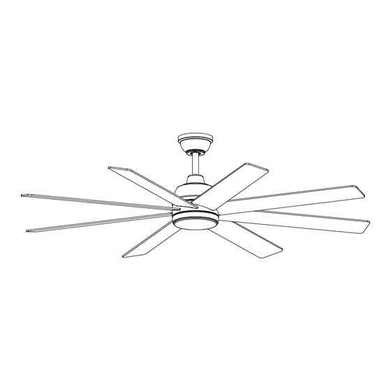
PARKMAN 62-INCH CEILING FAN
Questions, problems, missing parts?
Before returning to the store, call Hampton Bay Customer Service
8 a.m. - 7 p.m., EST, Monday-Friday, 9 a.m. - 6 p.m., EST, Saturday
1-855-HD-HAMPTON
needs. Thank you for choosing Hampton Bay!
HAMPTONBAY.COM
THANK YOU
Item # 1012 281 172
Model #52462
62-PARK-RV4-09162024
Scan for text based
Scan for online product
customer support
warranty information
Advertisement
Table of Contents

Subscribe to Our Youtube Channel
Related Manuals for HAMPTON BAY PARKMAN 52462


Summary of Contents for HAMPTON BAY PARKMAN 52462
- Page 1 THANK YOU We appreciate the trust and confidence you have placed in Hampton Bay through the purchase of this ceiling fan. We strive to continually create quality products designed to enhance your home. Visit us online to see our full line of products available for your home improvement...
-
Page 2: Table Of Contents
Table of Contents Safety Information ........2 Assembly. -
Page 3: Warranty
A certain amount of “wobble” is normal and should not be considered a defect. Servicing performed by unauthorized persons shall render the warranty invalid. There is no other express warranty. Hampton Bay hereby disclaims any and all warranties, including but not limited to those of merchantability and fitness for a particular purpose to the extent permitted by law. -
Page 4: Hardware Included
Pre-Installation (continued) HARDWARE INCLUDED NOTE: Hardware not shown to actual size. Part Description Quantity Blade screw Plastic wire connecting nut Hanger pin Locking pin Machine screw (Remote control wall cradle) Short tapered screw (Remote control wall cradle) Long tapered screw (Remote control wall cradle) - Page 5 Pre-Installation (continued) PACKAGE CONTENTS Part Description Quantity Part Description Quantity Slide-on mounting bracket Light kit fitter assembly (inside canopy) Shatter resistant shade Ball/downrod assembly Receiver Canopy Remote control Decorative motor collar cover 3-pin extension wire (motor) Fan motor assembly 3-pin extension wire (light) Blade Battery Light kit pan...
-
Page 6: Installation
Installation MOUNTING OPTIONS NOTE: You may need a longer downrod to maintain WARNING: To reduce the risk of fire, electric shock proper blade clearance when installing on a steep, or personal injury, mount to an outlet box marked sloped ceiling. The maximum angle allowable is 15° “Acceptable for fan support of 35 lb (15.9 kg) or away from horizontal. -
Page 7: Preparing For Mounting
Assembly - Standard Ceiling Mount Preparing for mounting NOTE: The magnet is pre-attached on the canopy bottom cover for you to remove and install easily. □ Remove the magnetic canopy bottom cover (JJ) from the canopy (C) by pulling it off. □... -
Page 8: Assembly
Assembly - Standard Ceiling Mount (continued) Assembling the fan CAUTION: To ensure wobble-free operation and to avoid damage to the fan, the downrod (B) and the setscrew (KK) must be completely tightened. WARNING: Failure to properly install the locking pin (DD) could result in the fan becoming loose and possibly falling. -
Page 9: Installing The Receiver
Assembly - Hanging the Fan (continued) Hanging the fan □ Carefully lift the fan motor assembly (E) up to the slide-on mounting bracket (A). □ Insert the ball portion of the ball/downrod assembly (B) into the socket of the slide-on mounting bracket (A). □... -
Page 10: Making The Electrical Connections
Assembly - Hanging the Fan (continued) Wire Connections Making the electrical connections Single Wall Switch WARNING: To avoid possible electrical shock, turn the □ electricity off at the main fuse box before wiring. If you On a single switch the fan and light can be turned on feel you do not have enough electrical wiring knowledge or off together. - Page 11 Assembly - Hanging the Fan (optional) Wire Connections Wire Connections Dual Wall Switch No Wall Switch From Fan To Receiver □ On a dual switch the fan and light can be turned on or off 3-pin connector--------------- 3-pin connector separately. Make wire connections as follows, using the wire nuts (BB).
- Page 12 Assembly - Hanging the Fan (continued) Mounting the fan motor assembly (standard mount) WARNING: When using the standard ball/downrod mounting, the tab in the ring at the bottom of the slide- on mounting bracket (A) must rest in the groove of the hanger ball.
- Page 13 Assembly - Attaching the Light Kit Installing the light kit pan CAUTION: To reduce the risk of electric shock, disconnect the electrical supply circuit to the fan before installing the light fixture. □ Remove one screw (LL) from the black bracket below the fan motor assembly and loosen but do not remove the other two screws.
-
Page 14: Preparing The Remote Control
Assembly - Preparing the Remote Control Preparing the remote control NOTE: The remote control has already been paired to the ceiling fan for your convenience. If the remote control does not communicate with the fan, follow the pairing instructions below. NOTE: The remote control battery will weaken with age and should be replaced before leaking takes place, as this will damage the remote control. -
Page 15: Operating Your Fan And Remote Control
Operating Your Fan and Remote Control ALL ON/OFF LED speed Press and release the ALL button to turn the fan and light on or off. All On/ indicator NOTE: On start up your ceiling fan will oscillate back and forth. This is NORMAL OPERATION for DC ceiling fans as it goes through its calibration cycle. - Page 16 Assembly - Mounting the remote wall cradle NOTE: The remote wall cradle is designed to allow you to access an existing switch. The remote wall cradle can be mounted on the wall or to the face plate of a standard Toggle switch face plate toggle switch or a paddle switch.
-
Page 17: Care And Cleaning
Care and Cleaning WARNING: Make sure the power is off before cleaning your fan. □ Because of the fan’s natural movement, some connections may become loose. Check the support connections, brackets, and blade attachments twice a year. Make sure they are secure. It is not necessary to remove the fan from the ceiling. □... - Page 18 Questions, problems, missing parts? Before returning to the store, call Hampton Bay Customer Service 8 a.m. – 7 p.m., EST, Monday – Friday, 9 a.m. – 6 p.m., EST, Saturday 1-855-HD-HAMPTON HAMPTONBAY.COM Retain this manual for future use. FCC Statement: This equipment has been tested and found to comply with the limits for a Class B digital device, pursuant to Part 15 of the FCC Rules. These limits are designed to provide reasonable protection against harmful interference in a residential installation.
- Page 19 GRACIAS Apreciamos la plena confianza que has depositado en Hampton Bay al comprar este ventilador de techo. Nos esforzamos en crear continuamente productos de calidad diseñados para mejorar tu hogar. Visítanos por Internet para ver nuestra línea completa de productos...
-
Page 20: Información De Seguridad
Tabla de contenido Información de seguridad ......2 Ensamblaje ......... .7 Garantía. -
Page 21: Garantía
No hay ninguna otra garantía expresa. Por este medio y en el alcance permitido por la ley, Hampton Bay queda exonerado de toda garantía, incluso, pero sin limitarse a ellas, aquellas de comercialización e idoneidad para un fin determinado. -
Page 22: Herrajes Incluidos
Preinstalación (continuación) HERRAJES INCLUIDOS NOTA: Los herrajes no se muestran en su tamaño real. Pieza Descripción Cantidad Tornillo de aspa del ventilador Tuerca de conexión de cable de plástico Pasador de soporte Pasador de cierre Tornillo maquinado (soporte de pared para control remoto) Tornillo cónico corto (soporte de pared para control remoto) Tornillo cónico largo (soporte de pared para control remoto) -
Page 23: Contenido Del Paquete
Preinstalación (continuación) CONTENIDO DEL PAQUETE Pieza Descripción Cantidad Pieza Descripción Cantidad Soporte de montaje deslizante Conjunto del soporte del kit de luz (dentro de la cubierta) Pantalla resistente a impactos Conjunto de tubo bajante/esfera Receptor Cubierta Control remoto Cubierta decorativa del collarín del motor Cable de extensión de 3 clavijas Conjunto del motor del ventilador (motor) -
Page 24: Instalación
Instalación OPCIONES DE MONTAJE NOTA: Tal vez necesites un tubo bajante más largo para ADVERTENCIA: Para reducir el riesgo de incendio, descarga mantener la altura mínima adecuada de las aspas, al instalar el eléctrica o lesiones personales, instala en caja eléctrica clasificada ventilador en un techo inclinado. - Page 25 Ensamblaje - Montaje estándar en techo Cómo preparar el montaje NOTA: El imán viene prefijado en la tapa inferior de la cubierta para quitar e instalar fácilmente. □ Retira la tapa inferior magnética (JJ) de la cubierta (C), tirando de ella hasta soltarla.
- Page 26 Ensamblaje - Montaje estándar en techo (continuación) Cómo ensamblar el ventilador CUIDADO: Para asegurarte de que no hay oscilación durante la operación y evitar daños al ventilador, el tubo bajante (B) y el tornillo del fijación (KK) tienen que ser completamente ajustados. ADVERTENCIA: Si el pasador de cierre no se instala correctamente (DD), es posible que el ventilador se afloje y caiga.
-
Page 27: Ensamblaje
Ensamblaje - Cómo colgar el ventilador (continuación) Cómo colgar el ventilador □ Levanta con cuidado el conjunto del motor del ventilador (E) hasta el soporte de montaje deslizante (A). □ Inserta la esfera del conjunto del tubo bajante/esfera (B) en el casquillo del soporte de montaje deslizante (A). - Page 28 Ensamblaje - Cómo colgar el ventilador (continuación) Conexiones de los cables Cómo hacer las conexiones eléctricas Interruptor de pared sencillo ADVERTENCIA: Para evitar una posible descarga eléctrica, □ desconecta la electricidad en la caja principal de fusibles antes de Con un solo interruptor, el ventilador y la luz se pueden cablear.
- Page 29 Ensamblaje - Cómo colgar el ventilador (opcional) Conexiones de los cables Conexiones de los cables Interruptor de pared doble Sin interruptor de pared Del ventilador Al receptor □ Con un interruptor doble, el ventilador y la luz se pueden Conector de 3 clavijas---------------Conector de 3 clavijas encender o apagar por separado.
- Page 30 Ensamblaje - Cómo colgar el ventilador (continuación) Cómo montar el conjunto del motor del ventilador (montaje estándar) ADVERTENCIA: Cuando uses el montaje del tubo bajante/ esfera estándar, la pestaña en el aro en la parte inferior del soporte de montaje deslizante (A) tiene que encajar en la ranura de la esfera de soporte.
- Page 31 Ensamblaje - Cómo instalar el kit de luz Cómo instalar la carcasa del kit de luz CUIDADO: Para disminuir el riesgo de descarga eléctrica, desconecta el circuito de energía del ventilador antes de instalar la lámpara. □ Quita un tornillo (LL) del soporte negro bajo el conjunto del motor del ventilador y afloje, pero no retire, los otros dos tornillos..
- Page 32 NOTA: El ventilador se puede controlar con hasta tres controles remotos. Para ordenar controles remotos adicionales, llama a Servicio al Cliente de Hampton Bay al 1-855-HD-HAMPTON. NOTA: El ventilador sólo puede ser controlado por 3 controles remotos como máximo al mismo tiempo después del "Aprendizaje".
- Page 33 Cómo usar tu ventilador y control remoto TODO ENCENDIDO/APAGADO Presiona y suelta el botón ALL para encender o apagar el ventilador y la luz. NOTA: Al encenderse, el ventilador de techo oscilará hacia Todo Indicador de adelante y hacia atrás. Esta es la OPERACIÓN NORMAL para los encendido/ velocidad LED ventiladores de techo de CC a medida que pasan por su ciclo de...
- Page 34 Ensamblaje - Montaje del soporte de pared para control remoto NOTA: El soporte de pared para control remoto está diseñado para permitirte acceder a un interruptor disponible. El soporte de pared para control remoto puede montarse en la pared o en Placa frontal del interruptor de palanca Toggle switch face plate la placa frontal de un interruptor de palanca estándar o de un...
-
Page 35: Mantenimiento Y Limpieza
Mantenimiento y limpieza ADVERTENCIA: Antes de limpiar el ventilador, asegúrate de que la corriente esté desconectada. □ Debido al movimiento natural del ventilador, algunas conexiones pueden aflojarse. Revisa dos veces al año las conexiones de soporte, los soportes y los accesorios de las aspas. Comprueba que estén seguros. No es necesario desmontar el ventilador del techo. □... - Page 36 ¿Preguntas? Antes de devolver a la tienda, llama al Servicio al Cliente de Hampton Bay de lunes a viernes de 8 a.m. a 7 p.m. (Hora del Este) o los sábados de 9 a.m. a 6 p.m. (Hora del Este).
Need help?
Do you have a question about the PARKMAN 52462 and is the answer not in the manual?
Questions and answers