Table of Contents
Advertisement
Available languages
Available languages
Quick Links
Item #1011 954 860
Model #52435
36-NADE-RV2-07252024
USE AND CARE GUIDE
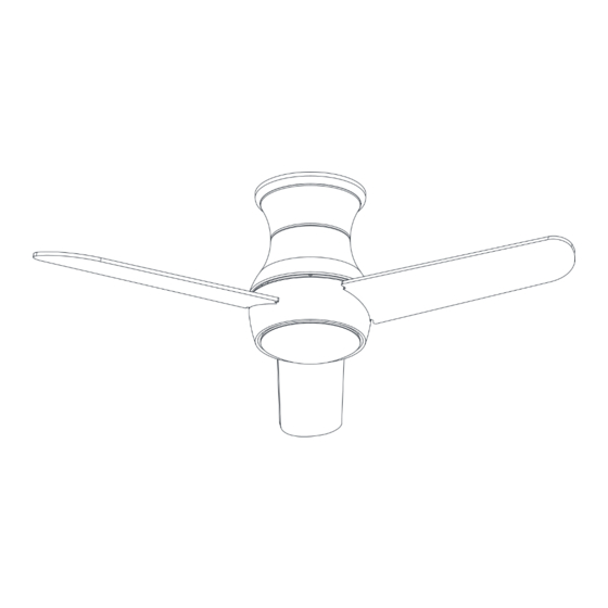
NADERBURY 36-INCH CEILING FAN
Questions?
Before returning to the store, call Hampton Bay Customer Service
8 a.m. - 7 p.m., EST, Monday-Friday, 9 a.m. - 6 p.m., EST, Saturday
1-855-HD-HAMPTON
HAMPTONBAY.COM
To view an instructional video on how to install this product:
1. Go to www.homedepot.com and enter either the item
or model number, found in the top right corner of the cover of
this instruction manual, in the search eld.
2. Click on your product from the list of search results and
Scan for text based
Scan for online product
click on the video link in the "Product Overview" section.
customer support
warranty information
THANK YOU
We appreciate the trust and confidence you have placed in Hampton Bay through the purchase of this ceiling fan. We strive to continually create
quality products designed to enhance your home. Visit us online to see our full line of products available for your home improvement needs.
Thank you for choosing Hampton Bay!
Advertisement
Chapters
Table of Contents

Related Manuals for HAMPTON BAY NADERBURY 52435


Summary of Contents for HAMPTON BAY NADERBURY 52435
- Page 1 THANK YOU We appreciate the trust and confidence you have placed in Hampton Bay through the purchase of this ceiling fan. We strive to continually create quality products designed to enhance your home. Visit us online to see our full line of products available for your home improvement needs.
-
Page 2: Table Of Contents
Table of Contents Safety Information................2 Assembly..................7 Warranty..................3 Operation..................15 Pre-Installation................3 Care and Cleaning.................16 Installation..................6 Troubleshooting................16 Safety Information READ AND SAVE THESE INSTRUCTIONS. WARNING: To reduce the risk of personal injury, do not bend the blade brackets (also referred to as flanges) during assembly or after installation. -
Page 3: Warranty
A certain amount of “wobble” is normal and should not be considered a defect. Servicing performed by unauthorized persons shall render the warranty invalid. There is no other express warranty. Hampton Bay hereby disclaims any and all warranties, including but not limited to those of merchantability and fitness for a particular purpose to the extent permitted by law. -
Page 4: Hardware Included
Pre-Installation (continued) HARDWARE INCLUDED NOTE: Hardware not shown to actual size. Part Description Quantity Plastic wire connecting nut Machine screw (remote control wall cradle) Short tapered screw (remote control wall cradle) Long tapered screw (remote control wall cradle) Blade attachment screw... -
Page 5: Package Contents
Pre-Installation (continued) PACKAGE CONTENTS Part Description Quantity Part Description Quantity Mounting plate Light kit assembly Trim ring Shatter-resistant Fan motor assembly Receiver Remote control Blade Battery Light kit pan Remote control wall cradle with IMPORTANT: This product and/or components are governed by toggle spacer included one or more of the following U.S. -
Page 6: Installation
Installation MOUNTING OPTIONS WARNING: To reduce the risk of fire, electric shock or personal injury, mount to outlet box marked “Acceptable for fan support of 35 lb (15.9 kg) or less”, and use screws provided with the outlet box. An outlet box commonly used for the support of lighting fixtures may not be acceptable for fan support and may need to be replaced. - Page 7 Assembly - Hanging the Fan Attaching the mounting plate to the electrical box □ Turn the power off. □ Loosen the two mounting screws (GG) supplied with the outlet box, but do not remove the screws. □ Securely attach the mounting plate (A) to the outlet box by sliding the mounting plate (A) over the two mounting screws (GG) supplied with the outlet box.
-
Page 8: Assembly
Assembly - Hanging the Fan (continued) Wire connections - Making the electrical connections Single wall switch WARNING: To avoid possible electrical shock, turn the □ On a single switch the fan and light can be turned on or off electricity off at the main fuse box before wiring. If you feel you do not have enough electrical wiring knowledge or together. - Page 9 Assembly - Hanging the Fan (continued) Wire connections - Wire connections - Dual wall switch No wall switch □ □ On a dual switch the fan and light can be turned on or off Make wire connections from the fan to the receiver (K). separately.
-
Page 10: Installing The Receiver
Assembly - Hanging the Fan (continued) Installing the receiver Outlet box in the ceiling WARNING: To reduce the risk of fire or electrical shock, remember to disconnect power. The electrical wiring must meet all local and national electrical code requirements. The electrical source and fan must be 110/120 volt, 60HZ. - Page 11 Assembly - Attaching the Blades Attaching the blades to the motor □ Attach a blade (D) to the fan motor assembly (C) by inserting the blade (D) into slots in the side of the fan motor assembly (C) and aligning the three screws holes in the blade with the holes in the center flywheel and secure with screws (EE).
- Page 12 Assembly - Attaching the Light Kit (continued) Attaching the light kit fitter assembly □ Remove one screw (TT) from the light kit pan (E), and loosen, but do not remove, the other two screws. □ Connect the wires from the light kit fitter assembly (F ) to the wires from the fan motor assembly (C) by connecting the molded adaptor plugs together.
-
Page 13: Preparing The Remote Control
Preparing the Remote Control NOTE: The remote control has already been paired to the ceiling fan for your convenience. If the remote control does not communicate with the fan, follow the pairing instructions below. NOTE: The remote control battery will weaken with age and should be replaced before leaking takes place, as this will damage the remote control. - Page 14 Assembly - Mounting the remote wall cradle NOTE: The remote wall cradle is designed to allow you to access an existing switch. The remote wall cradle can be mounted on the wall or to the face plate of a standard toggle switch or a paddle switch.
-
Page 15: Operating - Your Fan And Remote Control
Operating - Your Fan and Remote Control ALL ON/OFF Press and release the ALL button to turn the fan and light on or off. LED speed All On/Off NOTE: On start up your ceiling fan will oscillate back and indicator forth. -
Page 16: Care And Cleaning
Care and Cleaning WARNING: Make sure the power is off before cleaning your fan. □ Because of the fan’s natural movement, some connections may become loose. Check the support connections, brackets, and blade attachments twice a year. Make sure they are secure. It is not necessary to remove the fan from the ceiling. □... - Page 17 Questions, problems, missing parts? Before returning to the store, call Hampton Bay Customer Service 8 a.m. – 7 p.m., EST, Monday – Friday, 9 a.m. – 6 p.m., EST, Saturday 1-855-HD-HAMPTON HAMPTONBAY.COM Retain this manual for future use. This equipment has been tested and found to comply with the limits for a Class B digital device, pursuant to Part 15 of the FCC Rules. These limits are designed to provide reasonable protection against harmful interference in a residential installation.
- Page 18 GRACIAS Apreciamos la plena confianza que has depositado en Hampton Bay al comprar este ventilador de techo. Nos esforzamos en crear continuamente productos de calidad diseñados para mejorar tu hogar. Visítanos por Internet para ver nuestra línea completa de productos...
-
Page 19: Información De Seguridad
Tabla de contenido Información de seguridad............2 Ensamblaje.................7 Garantía..................3 Operación.................15 Preinstalación................3 Mantenimiento y limpieza............16 Instalación..................6 Solución de problemas............16 Información de seguridad LEE Y GUARDA ESTAS INSTRUCCIONES. ADVERTENCIA: Para reducir el riesgo de lesiones personales, no dobles los soportes de las aspas (también llamados “rebordes”) durante el ensamblaje o después de la instalación. -
Page 20: Garantía
Cierta “oscilación” es normal y no debe considerase un defecto. Cualquier servicio prestado por personal no autorizado invalidará la garantía. No hay ninguna otra garantía expresa. Por este medio y en el alcance permitido por la ley, Hampton Bay queda exonerado de toda garantía, incluso, pero sin limitarse a ellas, aquellas de comercialización e idoneidad para un fin determinado. -
Page 21: Herrajes Incluidos
Preinstalación (continuación) HERRAJES INCLUIDOS NOTA: Los herrajes no se muestran en su tamaño real. Pieza Descripción Cantidad Tuerca de plástico para conectar cables Tornillo maquinado (soporte de pared del mando a distancia) Tornillo cónico corto (soporte de pared del mando a distancia) Tornillo cónico largo (soporte de pared del mando a distancia) Tornillo para montaje de aspas... -
Page 22: Contenido Del Paquete
Preinstalación (continuación) CONTENIDO DEL PAQUETE Pieza Descripción Cantidad Pieza Descripción Cantidad Placa de montaje Conjunto del kit de luz Aro de la moldura Resistente a impactos Conjunto del motor del ventilador Receptor Control remoto Aspa Batería Carcasa del kit de luz Soporte de pared para control IMPORTANTE: Este producto y/o sus componentes están protegidos por remoto con separador de... -
Page 23: Instalación
Instalación OPCIONES DE MONTAJE ADVERTENCIA: Para reducir el riesgo de incendio, descarga eléctrica o lesiones personales, instala solo en una caja eléctrica clasificada como “apropiada para sostener ventiladores de 15.9 kg (35 lb) o menos” y usa los tornillos que vienen con la caja eléctrica. Las cajas eléctricas que suelen utilizarse para el soporte de lámparas pudieran no servir como soporte del ventilador y tal vez deban reemplazarse. - Page 24 Ensamblaje - Cómo colgar el ventilador Cómo fijar la placa de montaje a la caja eléctrica □ Desconecta la electricidad. □ Afloja, sin quitarlos, los dos tornillos de montaje (GG) suministrados con la caja eléctrica. □ Fija con seguridad la placa de montaje (A) a la caja eléctrica deslizando aquella (A) sobre los dos tornillos (GG) suministrados con la caja eléctrica.
-
Page 25: Ensamblaje
Ensamblaje - Cómo colgar el ventilador (continuación) Conexiones de cables Cómo hacer las conexiones Interruptor de pared simple eléctricas □ Con un solo interruptor, el ventilador y la luz se pueden encender o apagar juntos. Haz las conexiones de la siguiente ADVERTENCIA: Para evitar una posible descarga eléctrica, desconecta la electricidad en la caja principal de fusibles antes de manera, usando las tuercas para cables (AA). - Page 26 Ensamblaje - Cómo colgar el ventilador (continuación) Conexiones de cables Conexiones de cables Interruptor de pared doble Sin interruptor de pared □ □ Con un interruptor doble, el ventilador y la luz se pueden Realiza las conexiones de cables desde el ventilador hasta la encender o apagar por separado.
- Page 27 Ensamblaje - Cómo colgar el ventilador (continuación) Cómo instalar el receptor Outlet box Caja eléctrica en el techo in the ceiling ADVERTENCIA: Para disminuir el riesgo de descarga eléctrica e incendios, recuerda desconectar la corriente. El cableado eléctrico tiene que cumplir todos los requisitos de los códigos eléctricos nacionales y locales.
- Page 28 Ensamblaje - Cómo montar las aspas Cómo conectar las aspas al motor □ Fija el aspa (D) al conjunto del motor del ventilador (C) insertando el aspa (D) en las ranuras del lado del conjunto del motor del ventilador (C) y alineando los tres orificios de tornillo en el aspa con los orificios en el volante central, y luego asegura con tornillos (EE).
- Page 29 Ensamblaje - Cómo instalar el kit de luz (continuación) Cómo instalar el conjunto del soporte del kit de luz □ Quita un tornillo (TT) de la carcasa del kit de luz (E) y afloja los otros dos, pero sin quitarlos. □...
- Page 30 Cómo preparar el control remoto NOTA: El control remoto ya ha sido configurado con el ventilador de techo para tu conveniencia. Si el control remoto no se comunica con el ventilador, sigue las instrucciones de configuración que aparecen a continuación. NOTA: La batería del control remoto se debilitará...
- Page 31 Ensamblaje - Cómo fijar el soporte de pared para control remoto NOTA: El soporte de pared remoto está diseñado para permitirte acceder a un interruptor existente. El soporte de pared remoto puede montarse en la pared o en la placa frontal de un interruptor de Placa frontal del interruptor de palanca palanca estándar o de un interruptor de paleta.
- Page 32 Cómo usar tu ventilador y el control remoto TODO ENCENDIDO Y APAGADO (ON/OFF) Presiona y suelta el botón ALL (Todo) para encender o apagar el ventilador y la luz. Todo NOTA: Al encender tu ventilador de techo oscilará hacia adelante Indicador encendido/ y hacia atrás.
-
Page 33: Mantenimiento Y Limpieza
Mantenimiento y limpieza ADVERTENCIA: Asegúrate de que la corriente esté desconectada antes de limpiar el ventilador. □ Debido al movimiento natural del ventilador, algunas conexiones pueden aflojarse. Revisa dos veces al año las conexiones de soporte, los soportes y los accesorios de las aspas. Comprueba que estén seguros. No es necesario desmontar el ventilador del techo. - Page 34 ¿Preguntas, problemas o piezas faltantes? Antes de devolver a la tienda, llama al Servicio al Cliente de Hampton Bay de lunes a viernes de 8 a.m. a 7 p.m. (Hora del Este) o los sábados de 9 a.m. a 6 p.m. (Hora del Este).
Need help?
Do you have a question about the NADERBURY 52435 and is the answer not in the manual?
Questions and answers