Advertisement
Available languages
Available languages
Quick Links
To view an instructional video on how to install this product:
1. Go to www.homedepot.com and enter either the Item or Model number, found
in the top right corner of the cover of this instruction manual, in the search field.
2. Click on your product from the list of search results and click on the video link
in the "Product Overview" section.
We appreciate the trust and confidence you have placed in Hampton Bay through the purchase of this ceiling fan. We strive to continually
create quality products designed to enhance your home. Visit us online to see our full line of products available for your home improvement
USE AND CARE GUIDE
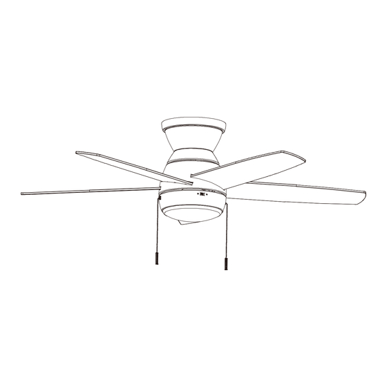
RIPLEE 44-INCH CEILING FAN
Questions, problems, missing parts?
Before returning to the store, call Hampton Bay Customer Service
8 a.m. - 7 p.m., EST, Monday-Friday, 9 a.m. - 6 p.m., EST, Saturday
1-855-HD-HAMPTON
needs. Thank you for choosing Hampton Bay!
HAMPTONBAY.COM
THANK YOU
Item # 1012 281 170,
1012 281 171
Model # 52444, 52449
44-RIPL-RV6-09232024
Scan for text based
Scan for online product
customer support
warranty information
Advertisement

Subscribe to Our Youtube Channel
Related Manuals for HAMPTON BAY RIPLEE 52444


Summary of Contents for HAMPTON BAY RIPLEE 52444
- Page 1 THANK YOU We appreciate the trust and confidence you have placed in Hampton Bay through the purchase of this ceiling fan. We strive to continually create quality products designed to enhance your home. Visit us online to see our full line of products available for your home improvement...
- Page 2 Table of Contents Table of Contents................2 Assembly....................7 Safety Information................2 Operation...................11 Warranty....................3 Care and Cleaning................12 Pre-Installation...................3 Troubleshooting................12 Installation..................6 Safety Information READ AND SAVE THESE INSTRUCTIONS. To reduce the risk of electric shock, ensure the electricity has WARNING: To reduce the risk of personal injury, do been turned off at the circuit breaker or fuse box before you not bend the blade brackets (also referred to as flanges) begin.
- Page 3 Servicing performed by unauthorized persons shall render the warranty invalid. There is no other express warranty. Hampton Bay hereby disclaims any and all warranties, including but not limited to those of merchantability and fitness for a particular purpose to the extent permitted by law.
- Page 4 Pre-Installation (continued) HARDWARE INCLUDED NOTE: Hardware not shown to actual size. Part Description Quantity Blade attachment screws Plastic wire connector Pull chain...
- Page 5 Pre-Installation (continued) PACKAGE CONTENTS Part Description Quantity Part Description Quantity Mounting plate Light kit fitter assembly Trim ring Light kit pan Fan-motor assembly Shatter resistant cover Blade IMPORTANT: This product and/or components are governed by one or more of the following U.S. Patents: 5,947,436;...
- Page 6 Installation MOUNTING OPTIONS WARNING: To reduce the risk of fire, electric shock or personal injury, mount to outlet box marked “Acceptable for fan support of 35 lb (15.9 kg) or less”, and use screws provided with the outlet box. An outlet box commonly used for the support of lighting fixtures may not be acceptable for fan support and may need to be replaced.
- Page 7 Assembly - Hanging the Fan Attaching the mounting plate to the Hanging the fan motor assembly electrical box □ Attach the trim ring (B) to the fan motor assembly (C) from WARNING: To avoid possible electrical shock, turn the the opening of the motor housing. Make sure the slots of electricity off at the main fuse box before wiring.
- Page 8 Assembly - Hanging the Fan (continued) Making the electrical connection Installing the motor assembly □ Remove two of the four screws (located diagonally WARNING: Each wire nut supplied with this fan is designed from each other) (NN) from the top of the mounting to accept up to one 12-gauge house wire and two wires plate (A) and loosen the other two screws (NN).
- Page 9 Assembly - Attaching the Blades Attaching the blades □ Attach a blade (D) to the fan motor assembly (C) by inserting the blade (D) into slots in the side of the fan motor assembly (C) and aligning the three screws holes in the blade with the holes in the center flywheel and secure with screws (AA).
- Page 10 Assembly - Attaching the Light Kit (continued) Attaching the light kit fitter assembly Installing the shatter resistant shade CAUTION: To reduce the risk of electric shock, WARNING: Allow the shatter resistant shade to cool disconnect the electrical supply circuit to the fan before completely before removing.
- Page 11 Operation NOTE: Wait for the fan to stop before reversing the direction of the blade rotation. Turn on the power and check the operation of the fan. The pull chain controls the fan speeds as follows: 1 pull - High, 2 pulls - Medium, 3 pulls - Low, 4 pulls - off The appropriate speed settings for warm or cool weather depends on factors such as the room size, ceiling height, and number of fans.
- Page 12 Care and Cleaning WARNING: Make sure the power is off before cleaning your fan. □ Because of the fan’s natural movement, some connections may become loose. Check the support connections, brackets, and blade attachments twice a year. Make sure they are secure. It is not necessary to remove the fan from the ceiling. □...
- Page 13 Questions, problems, missing parts? Before returning to the store, call Hampton Bay Customer Service 8 a.m. – 7 p.m., EST, Monday – Friday, 9 a.m. – 6 p.m., EST, Saturday 1-855-HD-HAMPTON HAMPTONBAY.COM Retain this manual for future use. FCC Statement: This equipment has been tested and found to comply with the limits for a Class B digital device, pursuant to Part 15 of the FCC Rules. These limits are designed to provide reasonable protection against harmful interference in a residential installation.
- Page 14 GRACIAS Apreciamos la plena confianza que has depositado en Hampton Bay al comprar este ventilador de techo. Nos esforzamos en crear continuamente productos de calidad diseñados para mejorar tu hogar. Visítanos por Internet para ver nuestra línea completa de productos...
- Page 15 Tabla de contenido Tabla de contenido................2 Ensamblaje..................7 Información de seguridad...............2 Operación..................11 Garantía....................3 Mantenimiento y limpieza.............12 Preinstalación..................3 Solución de problemas..............12 Instalación..................6 Información de seguridad LEE Y GUARDA ESTAS INSTRUCCIONES. Para reducir el riesgo de descarga eléctrica, asegúrate de que ADVERTENCIA: Para reducir el riesgo de lesiones la electricidad haya sido apagada en el interruptor o en la caja personales, no dobles los soportes de las aspas (también eléctrica antes de comenzar.
- Page 16 Cierta “oscilación” es normal y no debe considerase un defecto. Cualquier servicio prestado por personal no autorizado invalidará la garantía. No hay ninguna otra garantía expresa. Por este medio y en el alcance permitido por la ley, Hampton Bay queda exonerado de toda garantía, incluso, pero sin limitarse a ellas, aquellas de comercialización e idoneidad para un fin determinado.
- Page 17 Preinstalación (continuación) HERRAJES INCLUIDOS NOTA: Los herrajes no se muestran en su tamaño real. Pieza Descripción Cantidad Tornillo para montaje de aspas Tuerca de plástico para conectar cables Cadena de tracción...
- Page 18 Preinstalación (continuación) CONTENIDO DEL PAQUETE Pieza Descripción Cantidad Pieza Descripción Cantidad Placa de montaje Conjunto del kit de luz Aro de la moldura Carcasa del kit de luz Conjunto del motor del ventilador Pantalla resistente a impactos Aspa IMPORTANTE: Este producto y/o sus componentes están protegidos por una o más de las siguientes patentes de los EE.
- Page 19 Instalación OPCIONES DE MONTAJE ADVERTENCIA: Para reducir el riesgo de incendio, descarga eléctrica o lesiones personales, instala solo en una caja eléctrica clasificada como “apropiada para sostener ventiladores de 15.9 kg (35 lb) o menos” y usa los tornillos que vienen con la caja eléctrica. Las cajas eléctricas que suelen utilizarse para el soporte de lámparas pudieran no servir como soporte del ventilador y tal vez deban reemplazarse.
- Page 20 Ensamblaje - Cómo colgar el ventilador Cómo colgar el conjunto del Cómo fijar la placa de montaje a la motor del ventilador caja eléctrica □ Conecta el aro decorativo (B) al conjunto del motor del ADVERTENCIA: Para evitar posibles descargas ventilador (C) desde la abertura de la carcasa del motor.
- Page 21 Ensamblaje - Cómo colgar el ventilador (continuación) Cómo hacer las conexiones eléctricas Cómo instalar el conjunto del motor □ Retira dos de los cuatro tornillos (ubicados en diagonal ADVERTENCIA: Cualquier cable no incluido con este entre sí) (NN) de la parte superior de la placa de ventilador debe estar diseñado para aceptar un cable de montaje (A) y afloja los otros dos tornillos (NN).
- Page 22 Ensamblaje - Cómo fijar las aspas Cómo fijar las aspas □ Asegura el aspa (D) al conjunto del motor del ventilador (C) insertando el aspa (D) en las ranuras del costado del conjunto del motor del ventilador (C) y alineando los tres orificios de tornillo en el aspa con los orificios en el volante central;...
- Page 23 Ensamblaje - Cómo instalar el kit de luz (continuación) Cómo instalar el conjunto de Cómo instalar la pantalla resistente a instalación del kit de luz impactos CUIDADO: Para disminuir el riesgo de descarga eléctrica, ADVERTENCIA: Deja que la pantalla resistente a impacto desconecta el circuito de suministro eléctrico del ventilador se enfríe por completo antes de quitarla.
- Page 24 Operación NOTA: Espera a que se detenga el ventilador antes de invertir la dirección de giro de las aspas. Enciende la fuente de electricidad y verifica la operación del ventilador. El interruptor de cadena controla las velocidades del ventilador al jalar de ella de la siguiente manera: 1 vez: alta, 2 veces: media, 3 veces: baja, y 4 veces: apagado.
- Page 25 Mantenimiento y limpieza ADVERTENCIA: Asegúrate de que la corriente esté desconectada antes de limpiar el ventilador. □ Debido al movimiento natural del ventilador, algunas conexiones pueden aflojarse. Revisa dos veces al año las conexiones de soporte, los soportes y los accesorios de las aspas. Comprueba que estén seguros. No es necesario desmontar el ventilador del techo.
- Page 26 ¿Preguntas, problemas o piezas faltantes? Antes de devolver a la tienda, llama al Servicio al Cliente de Hampton Bay de lunes a viernes de 8 a.m. a 7 p.m. (Hora del Este) o los sábados de 9 a.m. a 6 p.m. (Hora del Este).
Need help?
Do you have a question about the RIPLEE 52444 and is the answer not in the manual?
Questions and answers