
Related Manuals for Spartus ProTIG 325P


Summary of Contents for Spartus ProTIG 325P
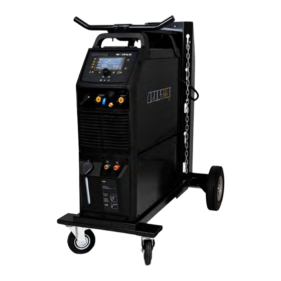
- Page 1 Inwertorowa spawarka SPARTUS® ProTIG Semiautomatic welder SPARTUS® ProTIG Instrukcja obsługi User’s manual 325P AC/DC...
- Page 2 I takie carried out in difficult conditions that właśnie są produkty SPARTUS® – przede expose welding equipment to extreme wszystkim niezawodne i trwałe, ale również tests of its strength. Only high quality wszechstronne.
-
Page 3: Table Of Contents
TABLE OF CONTENTS 1. SAFE USE – HAZARDS ASSOCIATED WITH ARC WELDING AND PLASMA CUTTING ....2 1.1 General safety rules ................................... 2 1.2 Electric shock can kill ................................2 1.3 Welding arc radiation can be dangerous ......................... 3 1.4 Vapours and gases can be dangerous ..........................3 1.5 Noise can be harmful ................................ -
Page 4: Safe Use - Hazards Associated With Arc Welding And Plasma Cutting
USER’S MANUAL 1. SAFE USE – HAZARDS ASSOCIATED WITH ARC WELDING AND PLASMA CUTTING Arc welding and plasma cutting are processes feeder fitted with spool and harness). Care that can pose hazards for the operator and per- shall be taken during manual handling. sons in his vicinity. -
Page 5: Welding Arc Radiation Can Be Dangerous
USER’S MANUAL • Power supply must never be connected Such radiation can be direct or reflected from before the accessories of SK sockets/con- surfaces such as bright metals and light colo- nectors are properly installed in the device. ured objects. •... -
Page 6: Noise Can Be Harmful
USER’S MANUAL Arc welding and allied processes produce wel- in case of an emergency, are in the imme- ding fume which may pollute the atmosphere diate vicinity. surrounding the work. Welding fume is a vary- • In closed rooms or in certain circumstances ing mixture of airborne gases and fine particles during outdoor operations, it may be re- which, if inhaled or swallowed, constitute a... -
Page 7: Fire Or Explosion Hazard
USER’S MANUAL source, • The surroundings of the work should be observed for an adequate period after its c) effective maintenance of sound protection termination. devices, • „Hot spots” and immediate surroundings d) indication as „ear protection areas” where should be observed until their temperature applicable, has dropped to normal. -
Page 8: Other Hazards
USER’S MANUAL • Keep your face and head away from the cy- Never aim the burner tip of the welding torch linder valve socket when the valve is being at your face, eyes or other people. opened. 1.7.4 Moving elements can be dangerous •... -
Page 9: Symbols Used In Instructions
USER’S MANUAL WARNING The maximum voltage of 15kV. Accidental pressing of the microswitch results in unintentional arc ignition. Never bring a bare hand close to the electrode, when the device is connected to a power source. 1.9 SYMBOLS USED IN INSTRUCTIONS We use this symbol to pay your attention about important information. -
Page 10: Assesment Of Area
Methods of reducing electromagnetic interference are listed in detail in the standard EN 60974-9 – „Arc welding equipment – Part 9: Installation and use”. 4. CONFORMITY WITH STANDARDS The SPARTUS® ProTIG 325P AC/DC is in conformity with the relevant Union harmonization legislation: LVD 2014/35/UE... -
Page 11: General Description
Thanks to the TIG Puls function, the device is perfect for welding very thin sheets made of stain- less steel, carbon steel, alloyed steel, titanium, magnesium, cuprum and aluminum. ProTIG 325P AC/DC have 10 memory channels. The user can easily save and recall the most used settings. -
Page 12: Technical Parameters Of Device
However it is not designed to be used outdoor during precipitation if it is not covered. 6.2 TECHNICAL PARAMETERS OF DEVICE SPARTUS® ProTIG 325P AC/DC Input ~3 x 400V ±10% 50/60 Hz Welding Current AC/DC [A] 10 –... -
Page 13: Installation And Use
Dimensions [mm] 260 × 700 × 485 7. INSTALLATION AND USE WARNING! SPARTUS® ProTIG AC/DC machines are intended for professional and industrial applications. Installation and use of the device may only be carried out appropriately trained professionals. It is forbidden to grinding and/or carrying out other locksmith works or mechanical working of metal in the vicinity of the ventilation opening of unit. -
Page 14: Description Of Construction
USER’S MANUAL 7.3 DESCRIPTION OF CONSTRUCTION Control plug socket (TIG) Coolant connection – input (TIG) SK socket „–” Coolant connection – output (TIG) Gas connector TIG Water cooling control connector SK socket „+” Water level calibration ON/OFF switch Coolant connection – input (MIG) Power source input Coolant connection –... -
Page 15: Connecting To Power Supply
USER’S MANUAL 7.4 CONNECTING TO POWER SUPPLY Requirements for power network parameters (voltage, permissible range of mains voltage fluctuations etc.) are given in the table with technical parameters of device and on the rating plate of welding machine. Before connecting the unit to the power source: •... - Page 16 USER’S MANUAL 7.5.2 Connecting the gas cylinder 1. The cylinder with appropriate shielding gas, should stand upright and be secured against tipping over in accordance with safety requirements. 2. Make sure that the valve cylinder is closed. 3. Connect properly gas regulator to cylinder valve. 4.
-
Page 17: Installation - Mma Welding
6. The device is ready to weld. Input 400V AC Control cable Weld material Work cable Electrode holder 7.7 DEVICE CONTROL PANEL – USING 7.7.1 Function panel description 面膜 BT TIG 321 LCD BT大号面板 0.6mm凸模标准英文面膜 8.105RM.304-A protig 325P AC/DC SAVE HOLE... - Page 18 USER’S MANUAL Parameter 1 key: Hot Start/Balance Welding mode key /AC frequency Output waveform key LCD screen Trigger mode selecting key 2T/4T Parameter 2 key: Arc Force/electrode Welding function key: Pulse/No Pulse/ diameter SingleSPOT/MultiSPOT Cooling mode selecting key: gas/liquid JOB key: save/recall mamory programs Function 2 key Function 1 key Parameters select/adjust knob...
- Page 19 Choice for the JOB memory channels: • select a saved memory channel PANEL DESCRIPTION DURING MMA WELDING 面膜 BT TIG 321 LCD BT大号面板 0.6mm凸模标准英文面膜 8.105RM.304-A protig 325P AC/DC SAVE HOLE A WELDING MODE KEY – MMA B OUTPUT WAVEFORM KEY– MMA DC / MMA AC G HOT START –...
- Page 20 PANEL DESCRIPTION DURING TIG HF/ TIG LIFT WELDING 面膜 BT TIG 321 LCD BT大号面板 0.6mm凸模标准英文面膜 8.105RM.304-A protig 325P AC/DC SAVE A WELDING MODE KEY TIG HF OR TIG Lift B OUTPUT WAVEFORM KEY – TIG DC / TIG AC (AC waveform: sine, square, triangle)
- Page 21 USER’S MANUAL PANEL DESCRIPTION DURING TIG PULSE WELDING P1 PULSE PEAK CURRENT P2 PULSE BASE CURRENT P3 PULSE FREQUENCY: 0.5 – 999Hz P4 PULSE WIDTH: 5 – 95% PANEL DESCRIPTION DURING TIG SPOT WELDING S1 WELDING CURRENT S2 WELDING TIME: 0.2 – 1.0s S3 WELDING BREAK TIME: off –...
-
Page 22: Device Control Panel - Using
USER’S MANUAL 7.7.4 Course of TIG welding process (2T) During TIG function 2T, you can not set the current parameters of the initial and final current. I (A) welding current I loosing the TIG torch switch the setting base current I arc ignation turning off arc t (s) -
Page 23: Wireless Remote Control Configuration
Electromagnetic valve is closed and stop argon flowing. Welding is finished. 7.8 WIRELESS REMOTE CONTROL CONFIGURATION ProTIG 325P AC/DC welding machines can be configured to communicate exclusively with wireless foot pedal or remote control panel. This is done by a simple process of synchronising the wireless remote control and the machine frequencies. -
Page 24: Pedal Switch Control
USER’S MANUAL 4. To connect remote control with second device, press the button COMMAND F again, then with the knob L se- lect the next free channel and press Connect M . 5. Turn on the power switch of the second welding machine to connect and con- trol the machine. -
Page 25: Environmental Protection
10. TROUBLESHOOTING Not all problems with functioning of the device, are the evidence of failure. You can independently carry out an analysis in search of probable failure. In case of doubt, please contact to SPARTUS® dealer or authorized service center. - Page 26 USER’S MANUAL TIG WELDING PROBLEMS Poorly connected TIG torch. Return cable The problem with TIG arc ignition (HF and no poorly connected or not connected. HF). There is a spark when HF works. Damaged current cable of TIG torch. Damaged microswitch. The problem with TIG arc ignition (HF and no Control plug is not connected.
- Page 28 MW MM SUBSCRIBE Subskrybuj kanał SPARTUS.INFO Subscribe to the channel SPARTUS.INFO...
Need help?
Do you have a question about the ProTIG 325P and is the answer not in the manual?
Questions and answers