Table of Contents
Advertisement
Quick Links
Advertisement
Table of Contents

Related Manuals for Spartus ProTIG 225P


Summary of Contents for Spartus ProTIG 225P
- Page 1 Semiautomatic welder SPARTUS® ProTIG 321P(W) AC/DC 225P AC/DC User’s manual...
- Page 2 Therefore, our offer covers such a wide assortment of products. Thank you very much for your trust in our company. We would like to invite you to familiarize yourself with the remaining products and offer at www.spartus. info or directly at a local distributor of SPARTUS® products.
-
Page 3: Table Of Contents
TABLE OF CONTENTS 1. SAFE USE – HAZARDS ASSOCIATED WITH ARC WELDING AND PLASMA CUTTING ....2 1.1 General safety rules ................................... 2 1.2 Electric shock can kill ................................2 1.3 Welding arc radiation can be dangerous ......................... 3 1.4 Vapours and gases can be dangerous ..........................3 1.5 Noise can be harmful ................................ -
Page 4: Safe Use - Hazards Associated With Arc Welding And Plasma Cutting
USER’S MANUAL 1. SAFE USE – HAZARDS ASSOCIATED WITH ARC WELDING AND PLASMA CUTTING Arc welding and plasma cutting are processes feeder fitted with spool and harness). Care that can pose hazards for the operator and per- shall be taken during manual handling. sons in his vicinity. -
Page 5: Welding Arc Radiation Can Be Dangerous
USER’S MANUAL • Power supply must never be connected Such radiation can be direct or reflected from before the accessories of SK sockets/con- surfaces such as bright metals and light colo- nectors are properly installed in the device. ured objects. •... -
Page 6: Noise Can Be Harmful
USER’S MANUAL Arc welding and allied processes produce wel- in case of an emergency, are in the imme- ding fume which may pollute the atmosphere diate vicinity. surrounding the work. Welding fume is a vary- • In closed rooms or in certain circumstances ing mixture of airborne gases and fine particles during outdoor operations, it may be re- which, if inhaled or swallowed, constitute a... -
Page 7: Fire Or Explosion Hazard
USER’S MANUAL source, • The surroundings of the work should be observed for an adequate period after its c) effective maintenance of sound protection termination. devices, • „Hot spots” and immediate surroundings d) indication as „ear protection areas” where should be observed until their temperature applicable, has dropped to normal. -
Page 8: Other Hazards
USER’S MANUAL • Keep your face and head away from the cy- Never aim the burner tip of the welding torch linder valve socket when the valve is being at your face, eyes or other people. opened. 1.7.4 Moving elements can be dangerous •... -
Page 9: Symbols Used In Instructions
USER’S MANUAL WARNING The maximum voltage of 15kV. Accidental pressing of the microswitch results in unintentional arc ignition. Never bring a bare hand close to the electrode, when the device is connected to a power source. 1.9 SYMBOLS USED IN INSTRUCTIONS We use this symbol to pay your attention about important information. -
Page 10: Assesment Of Area
Methods of reducing electromagnetic interference are listed in detail in the standard EN 60974-9 – „Arc welding equipment – Part 9: Installation and use”. 4. CONFORMITY WITH STANDARDS The SPARTUS® ProTIG 225P AC/DC and ProTIG 321P(W) AC/DC is in conformity with the re- levant Union harmonization legislation: LVD 2014/35/UE... -
Page 11: General Description
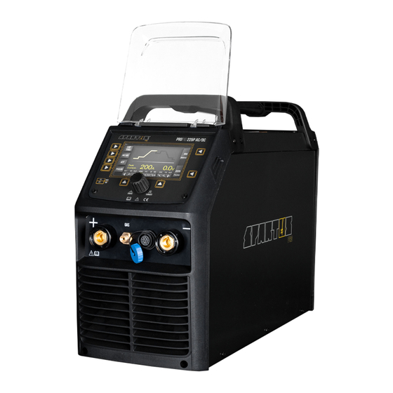
SPARTUS® ProTIG 225P AC/DC and ProTIG 321P(W) AC/DC It is a modern inverter welder that allows TIG AC/DC and MMA AC/DC. ProTIG 225P AC/DC is powered from a 230V one-phase network, with current up to 200A, and ProTIG 321P(W) AC/ DC –... -
Page 12: Technical Parameters Of Device
The device has a degree of protection IP23S. Which means that it is intended to be used in closed and covered areas and suitable for use outdoors. However it is not designed to be used outdoor during precipitation if it is not covered. 6.2 TECHNICAL PARAMETERS OF DEVICE ProTIG 225P ProTIG 321P(W) AC/DC AC/DC Input ~1 x 230V ±10% 50/60 Hz... -
Page 13: Installation And Use
(600 × 1150 × 1200)* version 321 with a cooler 7. INSTALLATION AND USE WARNING! SPARTUS® ProTIG AC/DC machines are intended for professional and industrial applications. Installation and use of the device may only be carried out appropriately trained professionals. It is forbidden to grinding and/or carrying out other locksmith works or mechanical working of metal in the vicinity of the ventilation opening of unit. -
Page 14: Description Of Construction
USER’S MANUAL 7.3 DESCRIPTION OF CONSTRUCTION Control plug socket (TIG) Coolant connection – input (TIG) SK socket „–” Coolant connection – output (TIG) Gas connector TIG Water cooling control connector SK socket „+” Water level calibration ON/OFF switch Coolant connection – input (MIG) Power source input Coolant connection –... -
Page 15: Connecting To Power Supply
USER’S MANUAL 7.4 CONNECTING TO POWER SUPPLY Requirements for power network parameters (voltage, permissible range of mains voltage fluctuations etc.) are given in the table with technical parameters of device and on the rating plate of welding machine. Before connecting the unit to the power source: •... - Page 16 USER’S MANUAL 7.5.2 Connecting the gas cylinder 1. The cylinder with appropriate shielding gas, should stand upright and be secured against tipping over in accordance with safety requirements. 2. Make sure that the valve cylinder is closed. 3. Connect properly gas regulator to cylinder valve. 4.
-
Page 17: Installation - Mma Welding
USER’S MANUAL INSTALLATION – MMA WELDING Before connecting hardware and shielding gas to the device, make sure that the device is discon- nected from power source and switch is in the OFF position. The welding polarity depends on the type of electrodes used. Before connecting the cables refer to the requirements specified by the manufacturer of electrodes. - Page 18 USER’S MANUAL Welding mode key Parameter 1 key: Hot Start/Balance Output waveform key LCD screen Parameter 2 key: Arc Force/ Trigger mode selecting key 2T/4T AC frequency Welding function key: Pulse/No Pulse/ Cooling mode selecting key: gas/liquid Spot (only 321 model) JOB key: save/recall mamory programs Function 2 key Function 1 key...
- Page 19 USER’S MANUAL K FUNCTION 2 KEY Choice for the TIG method: • Post Gas – gas flow time after welding • Final current value • Down Slope – welding current decrease time Choice for the SPOT welding mode: • Post Gas – gas flow time after welding Choice for the JOB memory channels: •...
- Page 20 USER’S MANUAL PANEL DESCRIPTION DURING TIG HF/ TIG LIFT WELDING A WELDING MODE KEY TIG HF OR TIG Lift B OUTPUT WAVEFORM KEY – TIG DC / TIG AC (AC waveform: sine, square, triangle) C TRIGGER MODE SELECTING KEY 2T/4T D WELDING FUNCTION KEY : PULSE/NO PULSE /SPOT (SPOT function is not available in Lift TIG welding) G BALANCE –...
- Page 21 USER’S MANUAL PANEL DESCRIPTION DURING TIG SPOT WELDING S1 WELDING CURRENT S2 WELDING TIME: 0.1 – 1.0s S3 WELDING BREAK TIME: off – 10.0s JOB PROGRAM PANEL DESCRIPTION J1 WELDING MODES Display of selected welding functions. J2 PARAMETERS All selected parameter values. J3 PROGRAM NUMBER You can save 10 programs with selected parameters using the JOB button.
- Page 22 USER’S MANUAL 7.7.4 Course of TIG welding process (2T) During TIG function 2T, you can not set the current parameters of the initial and final current. I (A) welding current I loosing the TIG torch switch the setting base current I arc ignation turning off arc t (s)
- Page 23 USER’S MANUAL 7.7.5 Course of TIG welding process (4T) During TIG 4T, it is possible to preset the current value of the initial and final current. With this feature, you can prevent flooding at the beginning of the weld and fill the crater formed at the end of the weld.
-
Page 24: Remote Control
USER’S MANUAL 7.8 REMOTE CONTROL CONTROL WIRE WIRELESS IN TORCH foot pedal remote foot pedal UP&DOWN potentiometer 225P AC/DC 321P(W) AC/DC UP&DOWN POTENTIOMETER WIRED FOOT PEDAL WIRELESS REMOTE CONTROL 7.8.1 Wireless remote control configuration (only for 321 model) ProTIG 321P(W) AC/DC welding machines can be configured to communicate exclusively with remote control panel. - Page 25 USER’S MANUAL 7.8.2 To synchronise a remote control to a machine 1. Ensure the welding power supply is switched off. 2. Press and hold the parameter select/adjust knob on the front panel of the power supply (2-4 seconds), while at the same time turning the machine ON using the ON/OFF switch 5 on the back of the welding power supply.
-
Page 26: Maintenance
USER’S MANUAL 8. MAINTENANCE WARNING! Before performing any maintenance or repairing of device, disconnect welding machine from the power source and wait at least 5 minutes. The voltage accumulated in capacitors should be discharged at this time to a safe level. But even after that operation you should be careful. Make sure that the device is disconnected from the power source, and switch is in the OFF posi- tion, before connecting accessories and shielding gas to the device. -
Page 27: Troubleshooting
10. TROUBLESHOOTING Not all problems with functioning of the device, are the evidence of failure. You can independently carry out an analysis in search of probable failure. In case of doubt, please contact to SPARTUS® dealer or authorized service center. - Page 28 MMA WELDING PROBLEMS Incorrect connection of return cable or there is no connection of return cable. Arc ignition problem. Too low welding current. Excessive spatter welding. The problem with Incorrect welding polarity. the arc ignition. Incorrect welding polarity. Unstable arc, excessive spatter welding, poor Electrode is damp or incorrectly heated weld quality –...
- Page 29 Notes...
- Page 30 Notes...
- Page 31 A masterly combination of high quality production, excellent parameters and ergonomics – these are fea- tures of the SPARTUS® Master series of devices, which were created with demanding welding jobs in mind. Precision, functionality, excellent parameters and resistance to high workloads –...
- Page 32 Videopresentation of products Subscribe to the channel SPARTUS.INFO...
Need help?
Do you have a question about the ProTIG 225P and is the answer not in the manual?
Questions and answers