YOKOGAWA ROTAMASS Total Insight User Manual
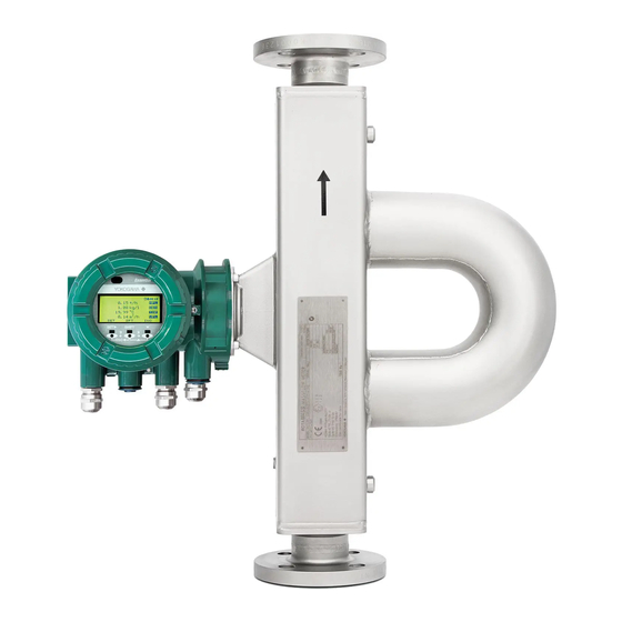
Coriolis mass flow and density meter
Hide thumbs
Also See for ROTAMASS Total Insight:
- General instruction manual (90 pages) ,
- User manual (76 pages)

Related Manuals for YOKOGAWA ROTAMASS Total Insight


Summary of Contents for YOKOGAWA ROTAMASS Total Insight
- Page 1 User's MASS ROTA Total Insight Coriolis Mass Flow and Density Meter Manual Quick Reference Instruction Manual for Spare IM01U10A01-00EN-R IM01U10A01-00EN-R, 2 edition, 2024-09-25...
-
Page 2: Table Of Contents
Table of contents Table of contents Introduction ............................... Scope of application.......................... Target group............................Applicable documents ........................Explanation of safety instructions and symbols ................Safety................................Technical conditions.......................... General safety instructions........................ Warranty..............................Product specification..........................Scope of delivery..........................Transport and storage ..........................10 Transport............................ - Page 3 Table of contents Installation of the Spare transmitter ....................28 7.2.1 Unpacking ..........................28 7.2.2 General installation instructions ................... 28 7.2.3 Transmitter installation......................29 7.2.3.1 Integral type transmitter installation ..................32 Wiring ..............................33 7.3.1 General wiring rules ......................33 7.3.2 Spare transmitter wiring .......................
-
Page 4: Introduction
These instructions apply to the following Rotamass Total Insight product families: Rotamass Total Insight Spare transmitter and Spare sThis instruction is intended to give instant support to re- place defective sensor or transmitter with spare device. Installation condition is considered as given, therefore not all installation details are covered. -
Page 5: Explanation Of Safety Instructions And Symbols
• Yokogawa Customer Portal (http://myportal.yokogawa.com/s/documents) • Yokogawa Device Lifecycle Management app Please enter the serial number of the device or scan the QR code on the device. Explanation of safety instructions and symbols Signal words Warning notices are intended to alert users to potential hazards when working with the flow meter. -
Page 6: Safety
/ or environmental harm. ▶ Yokogawa will not take any liability regarding damage caused by corrosion / erosion. ▶ If corrosion / erosion may happen, the user has to check periodically if the necessary wall thickness is still in place. - Page 7 Service Center. ▶ If Rotamass Total Insight is used to measure safety-related quantities, ensure that the transmitter does not display any error messages and, if applicable, the Total Health Check function is performed at regular inter- vals (see applicable Software Instruction Manuals IM01U10S␣␣-00␣␣-R).
-
Page 8: Warranty
The warranty terms for this device are described in the quotation. If a defect for which Yokogawa is responsible occurs in the device during the warranty period, Yokogawa will re- pair that defect at its own cost. If you believe that the device is defective, please contact us and provide a detailed description of the problem. -
Page 9: Product Specification
Quick Reference Instruction Manual for Spare Product specification Scope of delivery Product specification Scope of delivery The scope of delivery of the flow meter must be checked for completeness using the following list: Tab. 1: Overview: Scope of delivery of the flow meter Integral Remote Spare... -
Page 10: Transport And Storage
Quick Reference Instruction Manual for Spare Transport and storage Transport Transport and storage Transport The following rules apply when transporting the flow meter: ▶ Observe the transport-related instructions on packaging. ▶ In order to avoid damage, do not unpack the flow meter until it is at the installation site. ▶... -
Page 11: Storage
Quick Reference Instruction Manual for Spare Transport and storage Storage Storage Please note the following rules apply when storing the flow meter: Risk of damage to the flow meter due to storage in a damp environment NOTICE ▶ Protect flow meter from rain and humidity. ▶... -
Page 12: Sensor Replacement
▶ Switch off power supply and communication. ▶ Secure against inadvertent switch-on. Dismantling of the defective sensor The defective Rotamass Total Insight sensor has to be dismantled. The dismantling flow depends on the flow meter type (integral or remote). 6.1.1... - Page 13 Quick Reference Instruction Manual for Spare Sensor replacement Dismantling of the defective sensor Remote type Process connections Back cover for inputs and outputs, and power supply Terminal box Blind plug Cable entry for connecting cable Inputs/outputs cable entry Display cover Power supply cable entry Sensor connection terminal box cover 10 Connecting cable...
-
Page 14: Disconnect Remote Type Sensor
Quick Reference Instruction Manual for Spare Sensor replacement Dismantling of the defective sensor 6.1.2 Disconnect remote type sensor After power down and breaking the power circuit the sensor has to be disconnected by the following procedure: 1. Loosen the four screws from the neck cover and remove cover. 2. -
Page 15: Disconnect Integral Type Sensor
Quick Reference Instruction Manual for Spare Sensor replacement Dismantling of the defective sensor 6.1.3 Disconnect integral type sensor Disconnecting power, communication and grounding After power down and breaking the power circuit the sensor has to be disconnected. 1. Using an Allen wrench (Size: 3.0), tighten the locking screw on the back cover in clockwise direction. 2. -
Page 16: Remove Defective Sensor
Quick Reference Instruction Manual for Spare Sensor replacement Dismantling of the defective sensor Remove transmitter and disconnect from defective sensor 1. After disconnection the transmitter is removed by unscrewing the four clamping bolts. 2. Lift the transmitter housing: 3. Turn the transmitter housing around for disconnection. 4. -
Page 17: Installation Of The Spare Sensor
Quick Reference Instruction Manual for Spare Sensor replacement Installation of the Spare sensor Installation of the Spare sensor 6.2.1 Unpacking Note the following rules prior to installation: ▶ Check packaging and contents for damage. ▶ Do not remove protective materials such as protective stickers or caps on process connections until the start of the installation process. -
Page 18: Sensor Installation
Quick Reference Instruction Manual for Spare Sensor replacement Installation of the Spare sensor 6.2.3 Sensor installation Risk of injury due to escaping fluids, if pipe connection is faulty DANGER ▶ Correct slope and mismatch of pipe connections before inserting the sensor. Do the spare sensor installation in the opposite order as desribed before. -
Page 19: Wiring
▶ It is imperative that an original connecting cable and original glands from Rota Yokogawa are used. ▶ Install cables tension-free. Risk of sparking and damage to the flow meter due to incorrect wiring WARNING ▶... -
Page 20: Spare Sensor Wiring
Wiring work must only be performed at max. 80 % humidity and temperatures up to NOTICE 31 °C, linearly decreasing to 50 % relative humidity at 40 °C. Although Rota Yokogawa considers the guidelines of EMC, please be aware that con- NOTICE ducted and radiated electromagnetic emission may effect the EMC of adjacent areas. -
Page 21: Startup
Quick Reference Instruction Manual for Spare Sensor replacement Startup Startup 1. Activate external power switch. 2. Perform check of piping installation. 3. Check flow meter for device errors, warnings or alarms. Troubleshooting details can be found in General In- struction Manual IM 01U10B00-00␣␣-R. 4. -
Page 22: Set Up Process Variable Units
Quick Reference Instruction Manual for Spare Sensor replacement Parameter setting 6.5.3 Set up process variable units For usage of sensor constant download function the following process variables have to be adjusted. Tab. 2: Assignment: default setting for customer specific parameters Process variable Default unit Mass flow kg/h... -
Page 23: Transmitter Replacement
▶ Switch off power supply and communication. ▶ Secure against inadvertent switch-on. Dismantling of the defective transmitter The defective Rotamass Total Insight transmitter has to be dismantled. The dismantling flow depends on the flow meter type (integral or remote). 7.1.1... -
Page 24: Disconnecting Power, Communication And Grounding
Quick Reference Instruction Manual for Spare Transmitter replacement Dismantling of the defective transmitter Transmitter housing back cover Fig. 5: Connecting interfaces on transmitter housing back cover Terminal box power and I/O Grounding screw for connecting grounding conductor Grounding terminal for external potential equalization Power supply cable entry 7.1.2 Disconnecting power, communication and grounding... -
Page 25: Disconnect Remote Type Transmitter
Quick Reference Instruction Manual for Spare Transmitter replacement Dismantling of the defective transmitter 3. Disconnect the communication and I/O cables (avoid short circuit!) with the operating tool. Operation tool Grounding screw Fig. 6: Open transmitter terminal box power and I/O connection 4. -
Page 26: Disconnect Integral Type Transmitter
Quick Reference Instruction Manual for Spare Transmitter replacement Dismantling of the defective transmitter 7.1.4 Disconnect integral type transmitter After disconnection of power, communication and grounding, the transmitter has to be dismounted from sensor. 1. After disconnection the transmitter is removed by unscrewing the four clamping bolts. 2. -
Page 27: Remove Defective Transmitter (Remote Type)
Quick Reference Instruction Manual for Spare Transmitter replacement Dismantling of the defective transmitter 7.1.5 Remove defective transmitter (remote type) After disconnection the transmitter has to be removed by unscrewing the four clamping bolts. Fig. 7: Removal of defective transmitter from the mounting bracket The mounting bracket (U-bracket) remains for the installation of the spare transmitter. -
Page 28: Installation Of The Spare Transmitter
Quick Reference Instruction Manual for Spare Transmitter replacement Installation of the Spare transmitter Installation of the Spare transmitter 7.2.1 Unpacking Note the following rules prior to installation: ▶ Check packaging and contents for damage. ▶ Do not remove protective materials such as protective stickers or caps on process connections until the start of the installation process. -
Page 29: Transmitter Installation
Quick Reference Instruction Manual for Spare Transmitter replacement Installation of the Spare transmitter 7.2.3 Transmitter installation 1. Do the spare transmitter installation in the opposite order as desribed before. Details about transmitter in- stallation can be found in General Instruction Manual IM 01U10B00-00␣␣-R. In case of integral type device make sure to connect sensor and transmitter be- fore mounting. - Page 30 Quick Reference Instruction Manual for Spare Transmitter replacement Installation of the Spare transmitter 3. Remove the two screws from the display. 4. Remove the display from housing by pulling forward. 5. Rotate display and push back into housing in the orientation desired. IM01U10A01-00EN-R, 2 edition, 2024-09-25 30 / 48...
- Page 31 Quick Reference Instruction Manual for Spare Transmitter replacement Installation of the Spare transmitter The display can be removed and replaced by loosening the connector. NOTICE 6. Tighten screws. 7. Screw display cover back onto transmitter housing. 8. Using an Allen wrench (size: 3.0), turn the locking screw on display screw plug counter-clockwise to tighten. IM01U10A01-00EN-R, 2 edition, 2024-09-25 31 / 48...
-
Page 32: 7.2.3.1 Integral Type Transmitter Installation
Quick Reference Instruction Manual for Spare Transmitter replacement Installation of the Spare transmitter 7.2.3.1 Integral type transmitter installation The transmitter housing can be installed in any one of four orientations. Short-circuit hazard caused by penetrating water WARNING Failure of measuring electronics ▶... -
Page 33: Wiring
▶ It is imperative that an original connecting cable and original glands from Rota Yokogawa are used. ▶ Install cables tension-free. Risk of sparking and damage to the flow meter due to incorrect wiring WARNING ▶... -
Page 34: Spare Transmitter Wiring
Wiring work must only be performed at max. 80 % humidity and temperatures up to NOTICE 31 °C, linearly decreasing to 50 % relative humidity at 40 °C. Although Rota Yokogawa considers the guidelines of EMC, please be aware that con- NOTICE ducted and radiated electromagnetic emission may effect the EMC of adjacent areas. -
Page 35: Startup
7.5.1 Relevant parameters and storage The Rotamass Total Insight transmitter has four kinds of relevant parameters which must be adjusted to ensure a proper operation of the flowmeter: ▪ System relevant parameters - a device can be identified in one of the following ways: –... -
Page 36: Parameter Setting Procedure
Quick Reference Instruction Manual for Spare Transmitter replacement Parameter setting Sensor specific parameter contain: – Sensor coefficient SK20 – Density coefficient KD – Frequency FL20 They can be found additionaly on: – sensor calibration certificate – additional sensor nameplate 7.5.2 Parameter setting procedure There are multiple ways to setup parameters properly for device replacement. -
Page 37: Set Up Sensor Relevant And Sensor Specific Parameters
Quick Reference Instruction Manual for Spare Transmitter replacement Parameter setting 7.5.4 Set up sensor relevant and sensor specific parameters To use the sensor constant download function please execute the following sequence: 1. Access operation level [Specialist]. 2. Browse to [Diag/Service] ► [Param bkup/restore] ► [Bkup name]. Press [INC] to browse and [SET] to enter desired menus/parameters. - Page 38 Quick Reference Instruction Manual for Spare Transmitter replacement Parameter setting The default setting for customer specific parameters is as follows: Tab. 5: Assignment: default setting for customer specific parameters Parameter name: Default Setting: Parameter adjustment: Value Unit [Mass flow lowcut] [Net mass flow 1 lowcut] 0.0105 kg/h Recommended, if meter size is >06...
-
Page 39: Set Up System Related Parameters
Sensor constant for mass flow SK20 When a Rotamass Total Insight transmitter is used as a Spare transmitter for a Rotamass 3 series transmitter the SK20 value for the Rotamass 3 series device needs to be converted. The new SK20 depends on the meter size. -
Page 40: System Configuration And Operation
Quick Reference Instruction Manual for Spare System configuration and operation Display System configuration and operation Display All of the functions described here are also available via digital communication. Numerical values that are en- tered via the display are limited to 6 digits. Fig. 8: Display layout Measured quantities and units IR buttons... - Page 41 Quick Reference Instruction Manual for Spare System configuration and operation Display IR button functions IR button Display Function ▪ Apply setting SET ► ▪ Enter data ▪ Apply parameter ▪ Move cursor right or to the next position SHIFT ▪ Change function and display of SET and ▼ ▪...
- Page 42 Quick Reference Instruction Manual for Spare System configuration and operation Display Status icons HART Total health result: good Total health result: warning (only indicated when display total health re- (only indicated when display total health re- sult is active) sult is active) Total health result: bad state Tube Health Check with result: OK (only indicated when display total health re-...
- Page 43 Additional information about data recording can be found in the applicable Software Instruction Manual. Only use the microSD card included with the Rotamass Total Insight. Functionality of the device cannot be guaranteed if other cards are used. Tab. 9: Trend display...
-
Page 44: Transmitter Basic Settings By Display Menu
Quick Reference Instruction Manual for Spare System configuration and operation Transmitter basic settings by display menu Transmitter basic settings by display menu To limit access to device setup and parameters for configuring the operation of the device, 3 operation levels can be defined. -
Page 45: Setting Zero Point
2. Close valves in front of and after the flow meter and stop the flow. 3. Wait until density, temperature and pressure are stabilized. 4. In case of fluids, compare the density displayed on the Rotamass Total Insight with the fluid density in order to rule out gas accumulations in the measuring tube. -
Page 46: Transmitter Hardware Setting
Quick Reference Instruction Manual for Spare System configuration and operation Transmitter hardware setting Transmitter hardware setting The transmitter is equipped with DIP switches which can be used for specific settings. Some settings can be changed in the transmitter software as well. To access the switches follow instructions as below. - Page 47 Quick Reference Instruction Manual for Spare System configuration and operation Transmitter hardware setting 5. Remove the display from housing by slowly pulling forward. ð The switch can be seen. 6. Access desired switches. 7 6 5 4 Address 7. Push display into housing. 8.
- Page 48 ALFA LAVAL CORPORATE AB, SE FOUNDATION Fieldbus: registered trademark of FieldComm Group, Inc., US ROTAMASS: registered trademark of Rota Yokogawa GmbH & Co. KG, DE FieldMate: registered trademark of YOKOGAWA ELECTRIC CORPORATION registered trademark of SD-3C LLC.
Need help?
Do you have a question about the ROTAMASS Total Insight and is the answer not in the manual?
Questions and answers