
Related Manuals for YOKOGAWA RAMC


Summary of Contents for YOKOGAWA RAMC
- Page 1 Model RAMC User´s Manual Metal Short Stroke ROTAMETER IM 01R01B02-00E-E Rota Yokogawa GmbH & Co. KG IM 01R01B02-00E-E © Rheinstr. 8 Copyright 2003 (RYG) D-79664 Wehr 15th edition, November 2019 (RYG) Germany...
-
Page 2: Table Of Contents
4.1 Hints on flow rate measurement ..............4-1 4.2 Pulsation and pressure shock ...............4-1 4.3 Start of operation of electronic transmitter ..........4-1 5. Limit switches (Option /K1 to /K10) ..........5-1 All Rights Reserved. Copyright © 2003, Rota Yokogawa IM 01R01B02-00E-E 15th edition November 01, 2019 -00... - Page 3 7.4 Description of the HART 5- Parameter ............7-7 7.4.1 Process variables ....................7-8 7.4.2 Diagnostic- and Service-Menu ................7-8 7.4.3 Basic-Setup Menu ....................7-14 7.4.4 Detailed-Setup Menu ....................7-14 7.4.5 Review........................7-16 All Rights Reserved. Copyright © 2003, Rota Yokogawa IM 01R01B02-00E-E 15th edition November 01, 2019 -00...
- Page 4 8.1.5 Exchange of EEPROM and scale ................. 8-3 8.1.6 Exchange of the indicator ..................8-4 8.1.7 Troubleshooting ..................... 8-5 8.2 Sending an instrument back to service ............8-9 All Rights Reserved. Copyright © 2003, Rota Yokogawa IM 01R01B02-00E-E 15th edition November 01, 2019 -00...
- Page 5 9.5.2 Limit switches option /K1 to /K10 (/FS1 for USA) ........... 9-14 9.6 Intrinsically safe NEPSI (China) certified RAMC (/NS1) ........9-18 9.7 Intrinsically safe EAC (EAEU- countries) certified RAMC (/GS1) ..... 9-19 9.8 Intrinsically safe PESO (India) certified RAMC ..........9-19 9.9 Flame proof and dust proof ATEX certified RAMC (/KF1) ......9-20...
- Page 6 9.16.2 Safety Instructions .................... 9-29 9.16.3 Marking ......................9-29 9.17 Flame proof and dust proof RAMC with TS mark approval (Taiwan) .... 9-30 9.18 Flame proof and dust proof PESO (India) certified RAMC ......9-30 9.19 Flame proof KOSHA (Korea) certified RAMC ............ 9-30 10.
- Page 7 > CONTENTS APPENDIX 2. Safety Instrumented Systems Installation ....A2-1 A2.1 Scope and Purpose ................... A2-1 A2.2 Using RAMC for a SIS Application ............A2-1 A2.2.1 Safety Function....................A2-1 A2.2.2 Diagnostic Response Time ................A2-2 A2.2.3 Setup ........................A2-2 A2.2.4 Proof Testing .....................A2-2 A2.2.5 Repair and replacement ..................A2-2...
-
Page 8: Introduction
Before use, read this manual thoroughly and system familiarize yourself fully with the features, • Troubleshooting operations and handling of Rotameter RAMC to have • Maintenance and repair the instrument deliver its full capabilities and to ensure its efficient and correct use. -
Page 9: Safety
• The customer is fully responsible to select or not intended use. Rota Yokogawa is not liable proper materials to withstand his corrosive or for damage arising from such use. The flow meter erosive conditions. - Page 10 Rota Yokogawa. Rota Yokogawa does not assume liability for damage caused by unauthorized work on the flow meter or by improper use. • The RAMC flowmeter is a heavy instrument. Be careful that no damage is caused through accidentally dropping it, or by exerting excessive force on the RAMC flowmeter.
-
Page 11: Warranty
Yokogawa will repair that defect at its own cost. If you believe The RAMC is a variable area flow meter for volume flow or mass flow for clean gases and liquids. It is... -
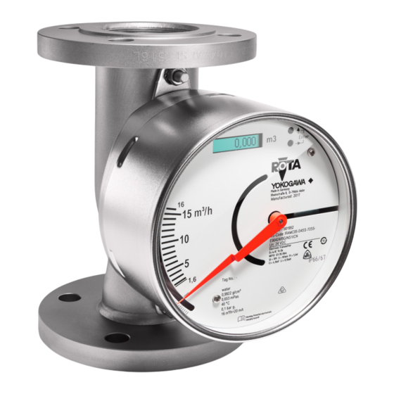
Page 12: Overview
- Pressure range of the flange and measuring tube e.g. PN40 - Material of wetted parts e.g. 1.4404 - Manufacturing code of the flange manufacturer - Lot. No. All Rights Reserved. Copyright © 2003, Rota Yokogawa IM 01R01B02-00E-E 15th edition November 01, 2019-00... - Page 13 Fluid data for specific fluid properties at process conditions Flow scale for specific fluid properties at process conditions Fig. 1-4 Scale example for -T -type All Rights Reserved. Copyright © 2003, Rota Yokogawa IM 01R01B02-00E-E 15th edition November 01, 2019-00...
-
Page 14: Precautions
(e.g. steel girders) should be kept at a distance of at least 250 mm from the RAMC. To avoid interference, the distance between two adjacent RAMC must be at least 300 mm (see Fig. 2-1). (212) (300) Fig. -
Page 15: Installation
Center gaskets and tighten nuts with a torque appropriate for the pressure range. If contamination or soiling of the RAMC is to be expected, a bypass should be installed to allow the removal of the instrument without interruption of the flow. -
Page 16: Wiring Of The Electronic Transmitter (-E, -H, -J) And Limit Switches (/K )
Please regard the drawings on the following pages. On the rear of the RAMC are two openings for cable glands for round cables with a diameter of 6 to 9 mm (not for Ex-d-type option / F1). Unused glands must be closed with a blind plug M16x1.5. (housing type 90) or with a blind plug M20x1.5 (housing type 91). - Page 17 Power supply plug Fig. 3-2 2-wire unit Terminal upper contact Terminal lower contact MIN or MAX, depending on model code Fig. 3-3 RAMC with 2 limit switches All Rights Reserved. Copyright © 2003, Rota Yokogawa IM 01R01B02-00E-E 15th edition November 01, 2019-00...
- Page 18 Operation keys LC-display Calibration-EEPROM Pulse output (option /CP) Cable gland Current output Mains connector Electronic transmitter PE connection Power supply circuit Fig. 3-4 4-wire unit All Rights Reserved. Copyright © 2003, Rota Yokogawa IM 01R01B02-00E-E 15th edition November 01, 2019-00...
- Page 19 EN 60947-5-6 (Namur) Fail-safe power supply Alternatively power supply option /WxE or /WxF can be used. Fig. 3-6 RAMC 2-wire unit with fail- safe limit switches Rotameter RAMC Electronic transmitter, -E, -H or -J U - 14 V Output 4 to 20 mA 20 mA Fig.
-
Page 20: Start Of Operation
When changing from a 3- to 2-wire configuration, the jumper should be set in place, and the current output has to be adjusted according to chapter 6.2.6. All Rights Reserved. Copyright © 2003, Rota Yokogawa IM 01R01B02-00E-E 15th edition November 01, 2019-00... -
Page 21: Limit Switches (Option /K1 To /K10)
Use of 2 standard limit switches (option /K3): The MIN-MIN and MAX-MAX functions have been integrated at the factory as MIN-MAX switches in the RAMC. The MIN-MIN or MAX-MAX function is set by adjusting the switching direction of the power supply. -
Page 22: Electronic Transmitter (-E)
• Detection of float blockage The setting of these parameters is done by two buttons. Digital display Engineering unit of the display Operation keys F61.EPS Fig. 6-1 Operation keys All Rights Reserved. Copyright © 2003, Rota Yokogawa IM 01R01B02-00E-E 15th edition November 01, 2019-00... - Page 23 F15: Temperature unit F15-2: degF F2-: Damping F21: Selection F21 0: 0 s F21 1: 1 s F21 5: 5 s F21 10: 10 s All Rights Reserved. Copyright © 2003, Rota Yokogawa IM 01R01B02-00E-E 15th edition November 01, 2019-00...
- Page 24 F72-3: 30 % of Qmax F73-1: 5 Minutes F73: Supervision time F73-2: 15 Minutes F74: Autozero F74-1: Execute Bold type = Factory Pre-setting *) Option /CP All Rights Reserved. Copyright © 2003, Rota Yokogawa IM 01R01B02-00E-E 15th edition November 01, 2019-00...
-
Page 25: Selection Of Indication Function (F11)
After changing the indicating function and measuring units the corresponding measuring unit label should be fixed on the right side next to the display. A preselection of matching stickers is included with the device. All Rights Reserved. Copyright © 2003, Rota Yokogawa IM 01R01B02-00E-E... -
Page 26: Setting The Unit (F12/F13)
(0 °C; 1 Atm.abs = 1.013 bar) Standard cubic feet scft (60 °F; 1 Atm.abs = 14.69 psi) Long ton Kilogram Pound Gallon (US) Time unit Hour Minute Second All Rights Reserved. Copyright © 2003, Rota Yokogawa IM 01R01B02-00E-E 15th edition November 01, 2019-00... - Page 27 A preselection of matching stickers is included with the device. Attention: When switching the mass/volume unit the totalizer is reset to zero. When changing the time unit the totalizer value remains unchanged. All Rights Reserved. Copyright © 2003, Rota Yokogawa IM 01R01B02-00E-E 15th edition November 01, 2019-00...
-
Page 28: Totalizer Reset (F14)
Note: If you press "↑" instead of "Enter", you can return from the selected point to the previous menu item without activating the displayed parameter. All Rights Reserved. Copyright © 2003, Rota Yokogawa IM 01R01B02-00E-E 15th edition November 01, 2019-00... -
Page 29: Setting Of Damping (F2-)
(Setting current to 20 mA) Decrease F33 in steps of -1 (-20 µA) if 20 mA Enter ↑ Back to display mode ↑ Display mode All Rights Reserved. Copyright © 2003, Rota Yokogawa IM 01R01B02-00E-E 15th edition November 01, 2019-00... -
Page 30: Pulse Output (F34) (Option /Cp)
A perhaps necessary fine adjustment can be carried out with F32 or F33. WARNING Since YOKOGAWA does not have any influence on the custom-designed connection, the current output is not automatically adapted, if the connection is changed from 2 wire to 3 wire or vice versa. This must be manually carried out with the functions F32 and F33. - Page 31 Special case: If Qmax is higher than 10000, the pulse rate is decreased by factor 10 in both cases. That means: • F34 -2 second to last totalizer digit • F34 -3 third totalizer digit from the right All Rights Reserved. Copyright © 2003, Rota Yokogawa IM 01R01B02-00E-E 15th edition November 01, 2019-00...
- Page 32 • When changing the indication with F11 -3 to "%", the totalizer stops and the pulse output is switched off. • After switching power on one pulse is generated at the output. • For 2- respectively 3-wire-units the function F34 is not supported. All Rights Reserved. Copyright © 2003, Rota Yokogawa IM 01R01B02-00E-E 15th edition November 01, 2019-00...
-
Page 33: Error Messages (F4-)
Deactivate float-blocking-indication (possibly remove supervision time gone off float and clean) or run Autozero function In case of error the appropriate remedy has to be taken. All Rights Reserved. Copyright © 2003, Rota Yokogawa IM 01R01B02-00E-E 15th edition November 01, 2019-00... -
Page 34: Manual Adjustment (F5-)
Change state F51 -2 or -1 Take state Enter ↑ Back to display mode ↑ Display mode (*) -1: manual adjustment OFF; -2: manual adjustment ON All Rights Reserved. Copyright © 2003, Rota Yokogawa IM 01R01B02-00E-E 15th edition November 01, 2019-00... - Page 35 • The adjustment has to be finished and stored by pressing "↑". After storage the new adjustment is permanently available and can be switched "on" or "off" by function F51. All Rights Reserved. Copyright © 2003, Rota Yokogawa IM 01R01B02-00E-E 15th edition November 01, 2019-00...
- Page 36 (a real new flow scale without new calibration) or to order a new calibration by the manufacturer together with a new scale and EEPROM for the new fluid and/or new process conditions (new adjustment plus new calibration). All Rights Reserved. Copyright © 2003, Rota Yokogawa IM 01R01B02-00E-E 15th edition November 01, 2019-00...
-
Page 37: Revision Indication (F61/F62)
If you press " " instead of "Enter", you can return from the selected point to the previous ↑ menu item without activating the displayed parameter. All Rights Reserved. Copyright © 2003, Rota Yokogawa IM 01R01B02-00E-E 15th edition November 01, 2019-00... -
Page 38: Switching Between Standard Or Indicator On Extension (F64)
F64 allows switching between the standard calibration table and a calibration table for the indicator on extension (option /A16 for high temperatures). The adjustment has to be performed according to the RAMC type (MS code). This is done as follows:... -
Page 39: Float Blocking Indication (F7-)
4 bars will flash below the numbers. After approx. 80 seconds the current autozero value appears on the display. This value gets stored and will not be lost after power off/on the RAMC or after switching off/on the Float-Move-Detection-function. The stored value is typed over first after a renewed autozero. - Page 40 3 - wire 4 to 20 mA: Error condition: IA < 0.0 mA • 3 - wire 0 to 20 mA: Error condition: IA = 0.0 mA All Rights Reserved. Copyright © 2003, Rota Yokogawa IM 01R01B02-00E-E 15th edition November 01, 2019-00...
- Page 41 Float blockage Check float in tube, clean tube if necessary. Supervision time gone off Deactivate float blocking indication or run Autozero function. Factory defaults/Master Reset (F65) The RAMC is adjusted at delivery (Factory Setting): • F71 - 1 Float-Move-Detection •...
- Page 42 3 x → Selection Autozero Enter Inquire autozero value (80 s) Enter 0.000 Display autozero value (10 s) 0.xxx ↑ Back to display mode ↑ Display mode All Rights Reserved. Copyright © 2003, Rota Yokogawa IM 01R01B02-00E-E 15th edition November 01, 2019-00...
-
Page 43: Hart- Communication
7. HART- Communication 7.1 General RAMC with indicator type -H or -J have, additional to the current output, the possibility for HART-communication. Also without HART- communication the units are fully able to work. The HART- communication does not influence the current output, except in Multidrop-Mode (see below). -
Page 44: Multidrop Mode In The Case Of Using Hart 7
Select the desired transmitter. After that, normal communication to the selected transmitter is possible. To release multidrop mode, call up the Poll addr display and set the address to "0". All Rights Reserved. Copyright © 2003, Rota Yokogawa IM 01R01B02-00E-E... -
Page 45: Connection
EN 60947-5-6 (Namur) Power supply acc. EN 60947-5-6 (Namur) Alternatively power supply option /WxA or /WxB can be used. Fig. 7-1 RAMC 2-wire unit with Hart- communication All Rights Reserved. Copyright © 2003, Rota Yokogawa IM 01R01B02-00E-E 15th edition November 01, 2019-00... -
Page 46: Hart 5- Menu (Rev 01 Dd Rev 02)
Status mancal ON / OFF Activate/deactiv ON / OFF Set mancal points 5 % / 15 % / ... / 95 % / 105 % All Rights Reserved. Copyright © 2003, Rota Yokogawa IM 01R01B02-00E-E 15th edition November 01, 2019-00... - Page 47 Scale USL Snsr s/n Final assy no MS - Code Configure signal Flow damping Flow damp 0.25 sec Set damping 1.00 sec 5.00 sec 10.00 sec All Rights Reserved. Copyright © 2003, Rota Yokogawa IM 01R01B02-00E-E 15th edition November 01, 2019-00...
- Page 48 Dev Id Manufacturer Distributor Snsr s/n Final assy no Write protect Descriptor Message Date Poll addr Num req preams Num resp preams Long tag MS Code All Rights Reserved. Copyright © 2003, Rota Yokogawa IM 01R01B02-00E-E 15th edition November 01, 2019-00...
-
Page 49: Description Of The Hart 5- Parameter
Flow AO Current output in mA Flow URV Upper range value related to the current output Flow LRV Lower range value related to the current output All Rights Reserved. Copyright © 2003, Rota Yokogawa IM 01R01B02-00E-E 15th edition November 01, 2019-00... -
Page 50: Process Variables
Float blocking autozero on Power fail warn OFF/ON Power off has happened Oper timer error OFF/ON Operation timer fault Mancal active OFF/ON Manual calibration activated All Rights Reserved. Copyright © 2003, Rota Yokogawa IM 01R01B02-00E-E 15th edition November 01, 2019-00... - Page 51 <7. HART-COMMUNICATION> Error description: All Rights Reserved. Copyright © 2003, Rota Yokogawa IM 01R01B02-00E-E 15th edition November 01, 2019-00...
- Page 52 Set as 20 mA value: Current flow is set to 20 mA. Read new value: Read current flow for 20 mA. Leave as found: No change Exit Leave parameter All Rights Reserved. Copyright © 2003, Rota Yokogawa IM 01R01B02-00E-E 15th edition November 01, 2019-00...
- Page 53 By switching Temp max log off the values are not cleared. When exceeding the maximum temperature of 70 °C the error message "Temp over limit" appears. All Rights Reserved. Copyright © 2003, Rota Yokogawa IM 01R01B02-00E-E 15th edition November 01, 2019-00...
- Page 54 The stored values remain unchanged after power off and must be cleared by the user. The actual cycle is overwrit- ten automatically by a new one. Therefore only the last cycle is always stored. The default value for hysteresis is 30 seconds. All Rights Reserved. Copyright © 2003, Rota Yokogawa IM 01R01B02-00E-E 15th edition November 01, 2019-00...
- Page 55 At power off the time from parameter Operation time is stored in parameter Over time shadow. After power off/on the power fail warning is set. It can be cleared by Reset power fail. All Rights Reserved. Copyright © 2003, Rota Yokogawa IM 01R01B02-00E-E...
-
Page 56: Basic-Setup Menu
StdCuFt/h MetTon/h CuFt/h Kg/h Lton/h StdCuFt/h Lb/h ImpGal/h gal/h Cum/min Cum/min L/min NmlCum/min NmlCum/min Kg/min NmlL/min StdCuFt/min MetTon/min CuFt/min Kg/min Lton/min StdCuFt/min Lb/min ImpGal/min gal/min All Rights Reserved. Copyright © 2003, Rota Yokogawa IM 01R01B02-00E-E 15th edition November 01, 2019-00... - Page 57 Detailed setup Display selection Selection of measuring value on display Different if manual calibration is activated For standard calibration table: Flow/Totalizer/Temperature For manual calibration table: Percent/Temperature All Rights Reserved. Copyright © 2003, Rota Yokogawa IM 01R01B02-00E-E 15th edition November 01, 2019-00...
-
Page 58: Review
HART Universal Revision (5) Fld. Dev. rev.: Field device Revision HW rev.: Hardware Revision FW rev.: Firmware Revision ADJ-EE rev.: Adjustment-EEPROM Revision CAL-EE rev.: Calibration-EEPROM Revision All Rights Reserved. Copyright © 2003, Rota Yokogawa IM 01R01B02-00E-E 15th edition November 01, 2019-00... -
Page 59: Hart 7- Menu (Rev 10 Dd Rev 01)
Cfg chng count Event Status Event Status Configuration changed event pending Device status event pending More status available event pending First time Unack Event Triggered All Rights Reserved. Copyright © 2003, Rota Yokogawa IM 01R01B02-00E-E 15th edition November 01, 2019-00... - Page 60 Days Hours Minutes URV underrun time Days Hours Minutes Min overrun time 15 sec 30 sec 1 min 5 min 10 min Clear values perform All Rights Reserved. Copyright © 2003, Rota Yokogawa IM 01R01B02-00E-E 15th edition November 01, 2019-00...
- Page 61 Gas in Normal Cond Gas in Standard Cond Flow Reference Volume Flow Mass Flow Flow scale unit Scale USL [Unit] MS-Code RAMC s/n RAMC firmware rev. All Rights Reserved. Copyright © 2003, Rota Yokogawa IM 01R01B02-00E-E 15th edition November 01, 2019-00...
- Page 62 MetTon/min MetTon/h MetTon/d lb/s lb/min lb/h lb/d STon/h STon/min STon/d LTon/h LTon/min LTon/d Spcl Total reset perform Temperature unit degC degF All Rights Reserved. Copyright © 2003, Rota Yokogawa IM 01R01B02-00E-E 15th edition November 01, 2019-00...
- Page 63 Burst 1 Burst Vari- Flow variables able Code 1...8 Total Percent Temp Percent range Loop current Primary variable Secondary variable Tertiary variable Quaternary variable Not used All Rights Reserved. Copyright © 2003, Rota Yokogawa IM 01R01B02-00E-E 15th edition November 01, 2019-00...
- Page 64 Burst 2 Burst Vari- Flow variables able Code 1...8 Total Percent Temp Percent range Loop current Primary variable Secondary variable Tertiary variable Quaternary variable Not used All Rights Reserved. Copyright © 2003, Rota Yokogawa IM 01R01B02-00E-E 15th edition November 01, 2019-00...
- Page 65 Burst 3 Burst Vari- Flow variables able Code 1...8 Total Percent Temp Percent range Loop current Primary variable Secondary variable Tertiary variable Quaternary variable Not used All Rights Reserved. Copyright © 2003, Rota Yokogawa IM 01R01B02-00E-E 15th edition November 01, 2019-00...
- Page 66 Volatile memory error Watchdog reset executed Voltage conditions out of range Environ- mental conditions out of range Electronic failure Device configurati- on locked All Rights Reserved. Copyright © 2003, Rota Yokogawa IM 01R01B02-00E-E 15th edition November 01, 2019-00...
- Page 67 More Status Available Cold Start Confi- guration Changed Device Malfunc- tion Ext Dev Mainte- Status nance Latched required Value Device variable alert Critical Power Failure All Rights Reserved. Copyright © 2003, Rota Yokogawa IM 01R01B02-00E-E 15th edition November 01, 2019-00...
- Page 68 Configura- Status tion chan- ged event pending Device sta- tus event pending More status available event pending Read Event perform Data Clear Event perform Data All Rights Reserved. Copyright © 2003, Rota Yokogawa IM 01R01B02-00E-E 15th edition November 01, 2019-00...
- Page 69 Num resp preams MS-Code RAMC s/n RAMC firmware rev. Device Profile Revisions #´s Universal rev Fld Dev. rev Hardware rev Software rev ADJ-EE rev CAL-EE rev All Rights Reserved. Copyright © 2003, Rota Yokogawa IM 01R01B02-00E-E 15th edition November 01, 2019-00...
- Page 70 Gas in Operation Gas in Normal Cond Gas in Standard Cond Flow Reference Volume Flow Mass Flow HOT KEY Write protect Wrt enable 10 min New password All Rights Reserved. Copyright © 2003, Rota Yokogawa IM 01R01B02-00E-E 15th edition November 01, 2019-00...
-
Page 71: Description Of The Hart 7- Parameter
Current output in mA Loop current Data Quality Quality of current value Loop current Limit Status Limit status of current value Time stamp Real-Time clock time stamp All Rights Reserved. Copyright © 2003, Rota Yokogawa IM 01R01B02-00E-E 15th edition November 01, 2019-00... -
Page 72: Diagnostic- And Service-Menu
The marked errors/warnings are displayed on the HHT375/475 and DD/DTM. Clear all: The indicated error/warning can be reset or disabled by the clear all function. All Rights Reserved. Copyright © 2003, Rota Yokogawa IM 01R01B02-00E-E 15th edition November 01, 2019-00... - Page 73 7-31 <7. HART-COMMUNICATION> All Rights Reserved. Copyright © 2003, Rota Yokogawa IM 01R01B02-00E-E 15th edition November 01, 2019-00...
- Page 74 Locks the upper selection key on the display and the write access of a second master. Changes can only be made by the first HART master. The first master can switch to normal operation by unlock the device. All Rights Reserved. Copyright © 2003, Rota Yokogawa IM 01R01B02-00E-E 15th edition November 01, 2019-00...
- Page 75 5 %...105 % Set manual adjustment points See description of manual adjustment in chapter 6.2.9 Reset adjustment table Resets manual adjustment table to factory defaults All Rights Reserved. Copyright © 2003, Rota Yokogawa IM 01R01B02-00E-E 15th edition November 01, 2019-00...
- Page 76 When exceeding the maximum temperature of 70 °C the error message "Temp over limit" appears. By changing the unit (from degC to degF or vice versa) the Temp max log values are cleared Fig. 7-4 All Rights Reserved. Copyright © 2003, Rota Yokogawa IM 01R01B02-00E-E 15th edition November 01, 2019-00...
- Page 77 The actual cycle is overwritten automatically by a new one. The stored values will be cleared after power off. The default value for hysteresis is 30 seconds. Fig. 7-5 All Rights Reserved. Copyright © 2003, Rota Yokogawa IM 01R01B02-00E-E 15th edition November 01, 2019-00...
- Page 78 The time value is reset to "00:00:00" after 24 hours (23:59:59). After "Power on", "Master Reset" or "Device Reset" the Real-time Clock is set to its initial value: 01/01/1900 00:00:00 All Rights Reserved. Copyright © 2003, Rota Yokogawa IM 01R01B02-00E-E 15th edition November 01, 2019-00...
-
Page 79: Basic- Setup Menu
Setting the time with "Set Clock Time" as well as the date with "Set Clock Date" with the "475" will fail in setting the "Real Time Clock". The "Real Time Clock" is only readable by this tool. Remedy Setting the time and the date with the "DTM" under Yokogawa’s "Fieldmate Tool" will succeed in setting the "Real Time Clock". 7.6.3 Basic- Setup Menu... - Page 80 See chapter 7.6.9 PV is Assignment of primary variable SV is Assignment of secondary variable TV is Assignment of tertiary variable QV is Assignment of quaternary variable All Rights Reserved. Copyright © 2003, Rota Yokogawa IM 01R01B02-00E-E 15th edition November 01, 2019-00...
- Page 81 Field device Revision Hardware rev Hardware Revision Software rev Software Revision ADJ-EE rev Adjustment-EEPROM Revision CAL-EE rev Calibration-EEPROM Revision (s.7.6.4 Detail-Setup) Operation conditions (s.7.6.4 Detail-Setup) Medium data All Rights Reserved. Copyright © 2003, Rota Yokogawa IM 01R01B02-00E-E 15th edition November 01, 2019-00...
-
Page 82: Write Protect Menu
Selection of a new password by entering up to 8 character If 8 blanks are entered as new password, write protection is disabled. If the user password is lost, a joker password is available from the YOKOGAWA service department. 7.6.6 Review Menu... - Page 83 7-41 <7. HART-COMMUNICATION> Burst message RAMC transmitter can transmit three burst messages at the maximum. The parameters for Burst Message are as follows. • Burst Command • Update Period and Max Update Period • Burst Msg Trigger Mode Burst mode setting procedure [Root Menu] →...
- Page 84 Variables Rising cent, temp) Falling On-change Self-diagnosis infor- Cmd48: Read Additi- Continuous mation onal Device Status *1: Output the data with time and status. All Rights Reserved. Copyright © 2003, Rota Yokogawa IM 01R01B02-00E-E 15th edition November 01, 2019-00...
- Page 85 On-change In "On-change" mode, the Burst Message must be published when the source value on chan- ge established by the trigger value. All Rights Reserved. Copyright © 2003, Rota Yokogawa IM 01R01B02-00E-E 15th edition November 01, 2019-00...
- Page 86 Trigger Level Set Burst 3 Period Perform Method to select update/max update period Set Burst 3 Trigger Perform Method to select trigger conditions Burst 3 variables All Rights Reserved. Copyright © 2003, Rota Yokogawa IM 01R01B02-00E-E 15th edition November 01, 2019-00...
-
Page 87: Event Notification (Only Available In Hart 7)
Ext Dev Status Mask Bit mask assignment (see table on page 7-47) Device Diagnostic Status 0 Mask Device Specific Status 0 Mask Device Specific Status 1 Mask All Rights Reserved. Copyright © 2003, Rota Yokogawa IM 01R01B02-00E-E 15th edition November 01, 2019-00... - Page 88 Device Spec. Status 1 Latched Value Time First Unack Event Triggered Cfg Change Counter Latched Val Event Status Read Event Data Perform Clear Event Data Perform All Rights Reserved. Copyright © 2003, Rota Yokogawa IM 01R01B02-00E-E 15th edition November 01, 2019-00...
- Page 89 Oper timer error Operation timer fault 0x20 OFF/ON OFF/ON Man adjust act. Manual adjustment activated 0x40 OFF/ON OFF/ON FB indicat. act. Float-Move-Detection activated 0x80 OFF/ON OFF/ON All Rights Reserved. Copyright © 2003, Rota Yokogawa IM 01R01B02-00E-E 15th edition November 01, 2019-00...
-
Page 90: Trend Configuration (Only Available In Hart 7)
The sampling interval is selectable in the range of 1 s up to 2 h. The internal measurement cycle is 250 ms. The RAMC supports one ring buffer with 12 samples in length. The ring buffer is updated with samples of the desired device variable value at the rate indicate by the sample period. -
Page 91: Maintenance
-communicator Load HART ® - DD for contain DD for RAMC? RAMC in communicator. ® HART -communicator OK ? Change communicator. RAMC to Yokogawa Service All Rights Reserved. Copyright © 2003, Rota Yokogawa IM 01R01B02-00E-E 15th edition November 01, 2019-00... -
Page 92: Service
The RAMC is maintenance-free. If contamination of the measuring tube impairs the mobility of the float, the tube and the float have to be cleaned. To do this, the RAMC has to be removed from the pipe. Replacement or cleaning of the float: •... -
Page 93: Explosion Drawing
<8. SERVICE> 8.1.3 Explosion drawing Number Part Circlip (retainer) Float stop Float Float stop welded in Cone Indicator All Rights Reserved. Copyright © 2003, Rota Yokogawa IM 01R01B02-00E-E 15th edition November 01, 2019-00... -
Page 94: Electronic Transmitter
Solely the display and operation unit (LCD PCB) can be replaced. For this the unit has to be sent to Yokogawa service. -
Page 95: Exchange Of The Indicator
Switch off power. • For units with option / F1 wait more than 2 minutes before opening the indicator. • For RAMC with housing type 91 unlock the safety screw at the cover. • Unscrew cover of indication unit. •... -
Page 96: Troubleshooting
<8. SERVICE> 8.1.7 Troubleshooting In case the RAMC does not work properly, use the following flow charts for troubleshooting, then check, isolate and remedy the fault. Precision problems with "T" unit: execute test 1 Precision problems with "E" or "H" or "J" unit: execute test 1 and test 2 HART communication problems with "H"... - Page 97 Is the correct calibra on EEPROM inserted? calibra on EEPROM. Check error code as in chapter 6.2.8 and take Are bars in display flashing? corresponding countermeasure. All Rights Reserved. Copyright © 2003, Rota Yokogawa IM 01R01B02-00E-E 15th edition November 01, 2019-00...
- Page 98 6.2.2. Is the correct engineering unit shown Affix correct on the right next to the engineering unit label. LC-display? Send RAMC to Yokogawa Service All Rights Reserved. Copyright © 2003, Rota Yokogawa IM 01R01B02-00E-E 15th edition November 01, 2019-00...
- Page 99 Does HART -communicator Load HART - DD for contain DD for RAMC? RAMC in communicator. ® Change communicator. HART -communicator OK ? RAMC to Yokogawa Service All Rights Reserved. Copyright © 2003, Rota Yokogawa IM 01R01B02-00E-E 15th edition November 01, 2019-00...
-
Page 100: Sending An Instrument Back To Service
Installation and operation of the Rotameter RAMC in compliance with this manual is generally trouble-free. In case a RAMC has to be sent for repairs or checking to our service, please observe the following: YOKOGAWA may take the following measures to protect the environment and the safety of our employees... - Page 101 Name Date Signature All Rights Reserved. Copyright © 2003, Rota Yokogawa IM 01R01B02-00E-E 15th edition November 01, 2019-00...
-
Page 102: Explosion-Protected Type Instruments
<9. EXPLOSION-PROTECTED TYPE INSTRUMENTS> 9. Explosion-protected Type Instruments This is only applicable to the countries in European Union. All Rights Reserved. Copyright © 2003, Rota Yokogawa IM 01R01B02-00E-E 15th edition November 01, 2019-00... -
Page 103: General
(refer to General Specifications (GS) GS01R01B02-00E-E). If necessary, order an indicator with distance. 9.1.2 Flame proof In the RAMC with option /KF1, /EF1, /NF1, /GF1 the transmitter and the limit switches are mounted in a flame proof housing. Wait 2 minutes after switching power off before opening the cover. -
Page 104: Intrinsically Safe Atex Certified Components (/Ks1)
For example the type KFA6-SR2-Ex... (option (W2 ) according certificate PTB 00 ATEX 2081 (230V AC supply) or the type KFD2-SR2-Ex... (option (W4 ) according certificate PTB 00 ATEX 2080 (24V DC supply) can be used. All Rights Reserved. Copyright © 2003, Rota Yokogawa IM 01R01B02-00E-E... -
Page 105: Installation
L = 150 µH PTB 00ATEX 2081 PTB 99ATEX 2219X Fig. 9-1 RAMC with ATEX approval (option /KS1) with electronic transmitter, standard limit switches and power supply units with AC power supply. All Rights Reserved. Copyright © 2003, Rota Yokogawa IM 01R01B02-00E-E... - Page 106 L = 150 µH PTB 00ATEX 2080 PTB 99ATEX 2219X Fig. 9-2 RAMC with ATEX approval (option /KS1) with electronic transmitter, standard limit switches and power supply units with DC power supply. All Rights Reserved. Copyright © 2003, Rota Yokogawa IM 01R01B02-00E-E...
-
Page 107: Marking
PTB 00ATEX 2043 (230/115V AC) PTB 00ATEX 2042 (24V DC) Fig. 9-3 RAMC with ATEX approval (option /KS1) with electronic transmitter, fail-safe limit switches and power supply units with AC/DC power supply. 9.2.3 Marking Name plates of the electronic transmitter:... -
Page 108: Intrinsically Safe Atex Components For Use In Zone 2 (/Ks3)
Example: KFA-SR2-Ex ... (option / W2 ) according to certificate PTB 00 ATEX 2081 (230V AC supply) or KFD-SR2-Ex ... (option / W4 according to certificate PTB 00 ATEX 2080 (24V DC supply). All Rights Reserved. Copyright © 2003, Rota Yokogawa IM 01R01B02-00E-E... -
Page 109: Marking
Rota Yokogawa Ex ic IIC T6 Gc Rheinstr. 8 D-79664 Wehr Ui=30V Ii=101mA Pi=1.4W WT-MAG Mat. No. 16-8040 Li=0.15mH Ci=4.16nF Serial No, xxxxxxxx II 3G All Rights Reserved. Copyright © 2003, Rota Yokogawa IM 01R01B02-00E-E 15th edition November 01, 2019-00... -
Page 110: Intrinsically Safe Iecex- Certified Components (/Es1)
For example the type KFA6-SR2-Ex... (option (W2 ) according certificate IECEx PTB 11.0031 (230 V AC supply) or the type KFD2-SR2-Ex... (option (W4 ) according certificate IECEx PTB 11.0032 (24 V DC supply) can be used. All Rights Reserved. Copyright © 2003, Rota Yokogawa IM 01R01B02-00E-E 15th edition November 01, 2019-00... -
Page 111: Installation
L = 150 µH IECEx PTB 11.0031X IECEx PTB 11.0091X Fig. 9.4 RAMC with IECEx approval (Option /ES1) with electronic transmitter, standard limit switches and power supply units with AC power supply. 9.4.3 Marking Name plates of electronic transmitter: Ex ia IIC T6 Gb Rota Yokogawa Rheinstr. -
Page 112: Intrinsically Safe Fm (Usa + Canada) Components (/Fs1)
Control Equipment. Maintenance and repair: WARNING The instrument modification or part replacements by other than authorized representative of Rota Yokogawa is prohibited and will void the approval of FM Approvals. Marking: Name plates of electronic transmitter: IS-Cl. - Page 113 9-12 <9. EXPLOSION-PROTECTED TYPE INSTRUMENTS> Control Drawing electronic transmitter intrinsically safe All Rights Reserved. Copyright © 2003, Rota Yokogawa IM 01R01B02-00E-E 15th edition November 01, 2019-00...
- Page 114 FM CONTROL DRAWING 07.11.2000 Amann DRAWED WT-MAG 07.11.2000 Slotwinski CKECKED 08.09.06 Rü YOKOGAWA 09.06.06 Rü DWG. No.: 79664 WEHR 8160191 GERMANY Rev. UPDATE No. DATE EDITOR CHECKED All Rights Reserved. Copyright © 2003, Rota Yokogawa IM 01R01B02-00E-E 15th edition November 01, 2019-00...
-
Page 115: Limit Switches Option /K1 To /K10 (/Fs1 For Usa)
Maximum Entity Field Wiring Parameters: see FM-control Drawing 116-0165 on page 9-15 and 9-16 for intrinsic safety see FM-control Drawing 116-0155 on page 9-17 for nonincendive All Rights Reserved. Copyright © 2003, Rota Yokogawa IM 01R01B02-00E-E 15th edition November 01, 2019-00... - Page 116 Only valid as long as released in EDM or with a valid production documentation! scale: 1:1 date: 2015-Dec-08 Control Drawing respons. change notice 116-0165G approved NAMUR SENSORS – FM sheet 1 of 11 Twinsburg norm All Rights Reserved. Copyright © 2003, Rota Yokogawa IM 01R01B02-00E-E 15th edition November 01, 2019-00...
- Page 117 Only valid as long as released in EDM or with a valid production documentation! scale: 1:1 date: 2015-Dec-08 Control Drawing respons. change notice 116-0165G approved NAMUR SENSORS – FM sheet 11 of 11 Twinsburg norm All Rights Reserved. Copyright © 2003, Rota Yokogawa IM 01R01B02-00E-E 15th edition November 01, 2019-00...
- Page 118 9-17 <9. EXPLOSION-PROTECTED TYPE INSTRUMENTS> Control Drawing limit switches nonincendive All Rights Reserved. Copyright © 2003, Rota Yokogawa IM 01R01B02-00E-E 15th edition November 01, 2019-00...
-
Page 119: Intrinsically Safe Nepsi (China) Certified Ramc (/Ns1)
9-18 <9. EXPLOSION-PROTECTED TYPE INSTRUMENTS> 9.6 Intrinsically safe NEPSI (China) certified RAMC (/NS1) The RAMC with electronic transmitter (-E, -H or -J) with or without limit switches is certified as intrinsic safe unit with NEPSI approval. Certificate Nr.: GYJ15.1064 Type of protection:... -
Page 120: Intrinsically Safe Eac (Eaeu- Countries) Certified Ramc (/Gs1)
9-19 <9. EXPLOSION-PROTECTED TYPE INSTRUMENTS> 9.7 Intrinsically safe EAC (EAEU- countries) certified RAMC (/GS1) The RAMC with electronic transmitter (-E, -H or -J) with or without limit switches is certified as intrinsic safe unit with EAC approval. Certificate Nr.: RU С-DЕ.ГБО8.В.01183... -
Page 121: Flame Proof And Dust Proof Atex Certified Ramc (/Kf1)
9-20 <9. EXPLOSION-PROTECTED TYPE INSTRUMENTS> 9.9 Flame proof and dust proof ATEX certified RAMC (/KF1) 9.9.1 Technical data Certificate: IBExU 05 ATEX 1086 Flame proof: Ex db IIC T6 Gb Dust proof: Ex tb IIIC TX Db Max. surface temperature TX: Corresp. -
Page 122: Installation
100 °C. Cable glands and entry fittings (screwed conduit entries) as well as blind plugs of simple design may not be used. On connection of the RAMC /KF1 using a conduit entry approved for the purpose, the associated sealing facility must be arranged directly on the housing. -
Page 123: Flame Proof And Dust Proof Iecex Certified Ramc (/Ef1)
9-22 <9. EXPLOSION-PROTECTED TYPE INSTRUMENTS> 9.10 Flame proof and dust proof IECEx certified RAMC (/EF1) 9.10.1 Technical data Certificate: IECEx IBE12.0007 Flame proof: Ex db IIC T6 Gb Dust proof: Ex tb IIIC TX Db Max. surface temperature TX: Corresp. process temperature... -
Page 124: Installation
100 °C. Cable glands and entry fittings (screwed conduit entries) as well as blind plugs of simple design may not be used. On connection of the RAMC /EF1 using a conduit entry approved for the purpose, the associated sealing facility must be arranged directly on the housing. -
Page 125: Intrinsically Safe Atex Certified Components In Dust Proof Ramc Housing (/Ks2)
9-24 <9. EXPLOSION-PROTECTED TYPE INSTRUMENTS> 9.11 Intrinsically safe ATEX certified components in dust proof RAMC- housing (/KS2) Certificate: PTB 12 ATEX 2003 (Intrinsically safe electronic transmitter) PTB 99 ATEX 2219X (Intrinsically safe limit switches) (Pepperl&Fuchs) PTB 00 ATEX 2049X (Intrinsically safe fail-safe limit switches) (Pepperl&Fuchs) -
Page 126: Flame Proof And Dust Proof Nepsi (China) Certified Ramc (/Nf1)
100 °C. Cable glands and entry fittings (screwed conduit entries) as well as plugs of simple design may not be used. On connection of the RAMC with option /NF1 using a conduit entry approved for the purpose, the associated sealing facility must be arranged directly on the housing. -
Page 127: Operation
The instrument modification or parts replacement by other than authorized representatives of YOKOGAWA is prohibited and will void the certification. WARNING If the window of the cover is damaged the RAMC must be set out of operation. All Rights Reserved. Copyright © 2003, Rota Yokogawa IM 01R01B02-00E-E... -
Page 128: Flame Proof Eac (Eaeu- Countries) Certified Ramc (/Gf1)
9-27 <9. EXPLOSION-PROTECTED TYPE INSTRUMENTS> 9.14 Flame proof EAC (EAEU- countries) certified RAMC (/GF1) 9.14.1 Technical data Certificate: RU С-DЕ.ГБО8.В.01183 Explosion proof: 1Ex d IIC T1...T6 Housing: Painted aluminium casting type 91 Output signal (with electronic transmitter -E, -H or -J): 4 to 20 mA (2- wire unit, 3- wire unit);... -
Page 129: Atex Non-Electrical Ramc (/Kc1)
II2G Ex h IIC TX Gb II2D Ex h IIIC TX°C Db -25 °C to +90 °C or T -40 °C to +90 °C for option/A26 amb. amb. All Rights Reserved. Copyright © 2003, Rota Yokogawa IM 01R01B02-00E-E 15th edition November 01, 2019-00... -
Page 130: Eac Certified Non-Electrical Ramc (Eaeu- Countries) (/Gc1)
9-29 <9. EXPLOSION-PROTECTED TYPE INSTRUMENTS> 9.16 EAC certified non-electrical RAMC (EAEU- countries) (/GC1) 9.16.1 Technical data Applicable Standard: Gost 31441: 2011 Certificate: RU С-DЕ.ГБО8.В.001183 Explosion proof: II 2GD IIC TX TX = temperature class determined by the process temperature or max. surface temperature determined by the process temperature Ambient temperature: •... -
Page 131: Flame Proof And Dust Proof Ramc With Ts Mark Approval (Taiwan)
9-30 <9. EXPLOSION-PROTECTED TYPE INSTRUMENTS> 9.17 Flame proof and dust proof RAMC with TS mark approval (Taiwan) Registration Document: ML041200702782 Option /EF1 must be selected. Same data as IECEx-certifiied type (/EF1) For export to Taiwan please contact your Yokogawa representative regarding Taiwan Safety Mark. -
Page 132: Instructions For Ped
10-1 <10. INSTRUCTIONS FOR PED> 10. Instructions for PED RAMC is produced according the directive 2014/68/EU (Directive for Pressure Equipment PED). Measuring tubes: • Type of equipment: piping • Type of fluid: liquid and gas • Group of fluid: 1 and 2 •... - Page 133 10-2 <10. INSTRUCTIONS FOR PED> Dependence of the permissible max. effective pressure of the operating temperature: The pressure relevant temperature limits of the RAMC are: • -196 °C to 370 °C for units made of stainless steel. • -80 °C to 130 °C for units made from PTFE.
- Page 134 The dimensions of the flanges are the same. That means that DIN and EN fit one to another. The facing of the flanges has changed. This may effect the gaskets. All Rights Reserved. Copyright © 2003, Rota Yokogawa IM 01R01B02-00E-E...
- Page 135 Earthquake resistance - Damage of the mounting screws Check by user T111.EPS All Rights Reserved. Copyright © 2003, Rota Yokogawa IM 01R01B02-00E-E 15th edition November 01, 2019-00...
- Page 136 Any repair, modification or supplements or the installation of spare-parts is only permitted if it is done in accor- dance to this instruction manual. Other work must be agreed by YOKOGAWA beforehand. YOKOGAWA will not take over any liability for damages caused by unauthorized work on the instrument or prohibited usage of the instrument.
- Page 137 DD Rev 01 on label of electronic transmitter ® in HART - parameter „Detailed Setup / Device information / RAMC firmware rev.”: Vx.xx (e.g.Vx.xx = V1.30), see also chapter 7.6.4 ® in HART - communicator All Rights Reserved. Copyright © 2003, Rota Yokogawa...
-
Page 138: Appendix 2. Safety Instrumented Systems Installation
This document provides an overview of the user responsibilities for installation and operation of the Rota Yokogawa RAMC variable area flow meter in order to maintain the designed safety level. Items that will be addressed are proof testing, repair and replacement of the flow meter, reliability data, lifetime, environmental and application limits, and parameter settings. -
Page 139: A2.2.2 Diagnostic Response Time
A2.2.5 Repair and replacement Maintenance information can be found in chapter 8. If repair is to be performed with the process online RAMC variable area flow meter will need to be bypassed during the repair. The user should setup appropriate bypass procedures for that. -
Page 140: A2.2.6 Startup Time
The expected lifetime of the Yokogawa Rota Yokogawa RAMC variable area flow meter is 10 years. The reliability data listed in A2.2.7 is only valid for this period. The failure rates of the Rota Yokogawa RAMC variable area flow meter may increase sometime after this period. Reliability calculations based on the data listed in A2. 2.7 for Rota Yokogawa RAMC variable area flow meter lifetimes beyond 10 years may yield results that are too optimistic, i.e. -
Page 141: A2.3 Definitions And Abbreviations
A2.4.1 Safety related parameters The following results have been obtained from the assessment report Report No.: ROTA YOKOGAWA 05/04-20 R001 Version V5, Revision R0; May 2014 issued by exida. Average PFD values have been calculated considering a proof test coverage of 99 %, a mission time of 10 years and a Mean Time To Restoration of 24 hours. - Page 142 A2-5 <A2. SAFETY INSTRUMENTED SYSTEMS INSTALLATION> Tab. A2-3: Summary for RAMC ([V1]) with fail-safe limit switches – Failure rates Profile 3 Fail-safe Detected (λSD) 0 FIT Fail-safe Undetected (λSU) 45 FIT Fail Dangerous Detected (λDD) 10 FIT Fail Dangerous Undetected (λDU)
- Page 143 REGISTERED TRADEMARKS Rotameter is a trademark of Rota Yokogawa GmbH & Co. KG, a subsidiary of Yokogawa Electric Corporation, Japan. In the United Kingdom Rotameter is a trademark of Emerson Electric Co. HART : Registered trademark of HART Communication Foundation, Austin, TX, USA ®...
Need help?
Do you have a question about the RAMC and is the answer not in the manual?
Questions and answers