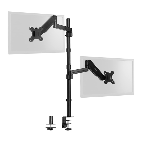
Vivo STAND-V012K Series Assembly Manual
Pneumatic arm dual monitor extra tall desk mount
Hide thumbs
Also See for STAND-V012K Series:
- Instruction manual (9 pages) ,
- Instruction manual (5 pages)


Need help?
Do you have a question about the STAND-V012K Series and is the answer not in the manual?
Questions and answers