Advertisement
www.ti.com
EVM User's Guide: TPS513885EVM
TPS513885 Step-Down Converter Evaluation Module
Description
The TPS513885 is a single, D-CAP3
synchronous buck converter requiring a very low
external component count. TPS513885EVM is a
fully assembled and tested circuit for evaluating the
TPS513885 converter. This EVM operates typical
19.5V input, and provides a 5.15V output at 12A.
Integrated low R
power MOSFETs enable high
DS(ON)
efficiency and offer ease of use with a minimal
external component count for space-constrained
power systems.
SLUUCZ6 – MAY 2024
Submit Document Feedback
Features
™
control mode,
•
5.5V to 22V input voltage range
•
5.15V fixed output voltage range
•
Support 12A continuous output current
•
Selectable PSM and OOA mode under light load
•
Fast load transient response
Applications
•
Notebook and PC computers
•
Ultrabook, tablet computers
•
TV,
•
Distributed power systems
Copyright © 2024 Texas Instruments Incorporated
STB
TPS513885 Step-Down Converter Evaluation Module
Description
1
Advertisement
Table of Contents

Related Manuals for Texas Instruments TPS513885EVM


Summary of Contents for Texas Instruments TPS513885EVM
- Page 1 5.5V to 22V input voltage range synchronous buck converter requiring a very low • 5.15V fixed output voltage range external component count. TPS513885EVM is a • Support 12A continuous output current fully assembled and tested circuit for evaluating the •...
-
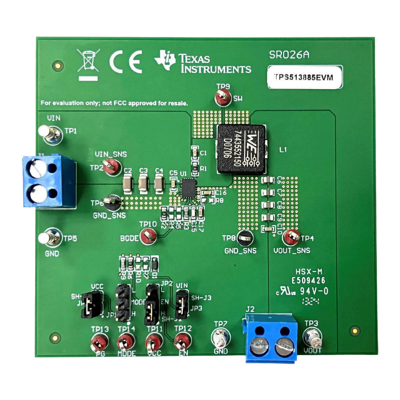
Page 2: Kit Contents
This user's guide describes the characteristics, operation, performance, and use of the Texas Instruments' TPS513885 evaluation module (EVM). The TPS513885EVM is designed to help user easily evaluate and test the operation and functionality of the TPS513885. This user's guide includes the following: •... -
Page 3: Device Information
Internal 5V LDO output. Power supply for internal analog circuits and driving. Enable input of buck converter MODE Mode selection pin BODE Injection point for loop response SLUUCZ6 – MAY 2024 TPS513885 Step-Down Converter Evaluation Module Submit Document Feedback Copyright © 2024 Texas Instruments Incorporated... - Page 4 8. Decrease load to 0A. Decrease input source voltage to 0V. Decrease EN source voltage to 0V. TPS513885 Step-Down Converter Evaluation Module SLUUCZ6 – MAY 2024 Submit Document Feedback Copyright © 2024 Texas Instruments Incorporated...
- Page 5 Figure 3-1 through Figure 3-10 present typical performance curves for the TPS513885EVM. Because actual performance data can be affected by measurement techniques and environmental variables, these curves are presented for reference and can differ from actual field measurements. 3.1.1 EVM Characteristics Table 3-1 lists the electrical characteristics.
- Page 6 Implementation Results www.ti.com 3.1.3 Operating Waveforms 3.1.3.1 Start-Up and Shutdown with EN The following figures show the TPS513885EVM start-up and shutdown waveforms relative to EN. EN = 2V/div Vout = 2V/div IL = 5A/div 800us/div Figure 3-3. Start-Up Relative to EN, V = 19.5V, I...
- Page 7 Implementation Results 3.1.3.2 Start-Up with VIN Figure 3-5 shows the TPS513885EVM start-up waveform relative to VIN. Vin = 10V/div Vout = 2V/div IL = 5A/div 2ms/div Figure 3-5. Start-Up Relative to VIN, V = 3.3V, I = 12A 3.1.3.3 Load Transient Response...
- Page 8 Figure 3-9 show the TPS513885EVM output voltage ripple. Vout = 20mV/div (AC coupled) SW = 10V/div 10us/div Figure 3-8. TPS513885EVM Output Voltage Ripple, I = 0.1A, PSM Mode TPS513885 Step-Down Converter Evaluation Module SLUUCZ6 – MAY 2024 Submit Document Feedback...
- Page 9 Implementation Results Vout = 20mV/div (AC coupled) SW = 10V/div 1us/div Figure 3-9. TPS513885EVM Output Voltage Ripple, I = 12A 3.1.4 Thermal Performance Figure 3-10 shows the thermal performance image. Figure 3-10. Thermal Performance, V = 19.5V, I = 12A, T = 25°C, No Airflow...
- Page 10 The following image shows the schematic for the TPS513885EVM. Figure 4-1. TPS513885EVM Schematic Diagram The default operating frequency of TPS513885EVM is 560kHz. If the user wants to test the device behavior at 920kHz (typical value), please remove R6 and use a jumper to short MODE to GND.
- Page 11 Figure 4-5. Bottom Copper (Top View) 4.2.1 Multi-Layer Stackup Figure 4-6. Layer Stackup 4.2.2 Component Drawings Figure 4-8. Bottom Component Drawing Figure 4-7. Top Component Drawing SLUUCZ6 – MAY 2024 TPS513885 Step-Down Converter Evaluation Module Submit Document Feedback Copyright © 2024 Texas Instruments Incorporated...
-
Page 12: Compliance Information
Unless otherwise noted in the Alternate Part Number or Alternate Manufacturer columns, all parts can be substituted with equivalents. 5 Compliance Information 5.1 Compliance and Certifications • TPS513885EVM EU Declaration of Conformity (DoC) for Restricting the use of Hazardous Substances (RoHS) 6 Additional Information 6.1 Trademarks D-CAP3 ™... -
Page 13: Related Documentation
Related Documentation 7 Related Documentation For related documentation, see the following: • TPS513885 5.5V to 24V, 12A Synchronous Buck Converter data sheet SLUUCZ6 – MAY 2024 TPS513885 Step-Down Converter Evaluation Module Submit Document Feedback Copyright © 2024 Texas Instruments Incorporated... - Page 14 STANDARD TERMS FOR EVALUATION MODULES Delivery: TI delivers TI evaluation boards, kits, or modules, including any accompanying demonstration software, components, and/or documentation which may be provided together or separately (collectively, an “EVM” or “EVMs”) to the User (“User”) in accordance with the terms set forth herein.
- Page 15 www.ti.com Regulatory Notices: 3.1 United States 3.1.1 Notice applicable to EVMs not FCC-Approved: FCC NOTICE: This kit is designed to allow product developers to evaluate electronic components, circuitry, or software associated with the kit to determine whether to incorporate such items in a finished product and software developers to write software applications for use with the end product.
- Page 16 www.ti.com Concernant les EVMs avec antennes détachables Conformément à la réglementation d'Industrie Canada, le présent émetteur radio peut fonctionner avec une antenne d'un type et d'un gain maximal (ou inférieur) approuvé pour l'émetteur par Industrie Canada. Dans le but de réduire les risques de brouillage radioélectrique à...
- Page 17 www.ti.com EVM Use Restrictions and Warnings: 4.1 EVMS ARE NOT FOR USE IN FUNCTIONAL SAFETY AND/OR SAFETY CRITICAL EVALUATIONS, INCLUDING BUT NOT LIMITED TO EVALUATIONS OF LIFE SUPPORT APPLICATIONS. 4.2 User must read and apply the user guide and other available documentation provided by TI regarding the EVM prior to handling or using the EVM, including without limitation any warning or restriction notices.
- Page 18 Notwithstanding the foregoing, any judgment may be enforced in any United States or foreign court, and TI may seek injunctive relief in any United States or foreign court. Mailing Address: Texas Instruments, Post Office Box 655303, Dallas, Texas 75265 Copyright © 2023, Texas Instruments Incorporated...
- Page 19 TI products. TI’s provision of these resources does not expand or otherwise alter TI’s applicable warranties or warranty disclaimers for TI products. TI objects to and rejects any additional or different terms you may have proposed. IMPORTANT NOTICE Mailing Address: Texas Instruments, Post Office Box 655303, Dallas, Texas 75265 Copyright © 2024, Texas Instruments Incorporated...
Need help?
Do you have a question about the TPS513885EVM and is the answer not in the manual?
Questions and answers