Table of Contents
Advertisement
Quick Links
TPS549D22EVM-784, 40-A Single Synchronous Step-Down
Converter With Full Differential Sense and PMBus™
This user's guide describes the characteristics, operation, and use of the TPS549D22 Evaluation Module
(EVM). The user's guide includes test information, descriptions, and results. A complete schematic
diagram, printed-circuit board layouts, and bill of materials are also included in this document. Throughout
this user's guide, the abbreviations EVM, TPS549D22EVM, and the term evaluation module are
synonymous with the TPS549D22EVM-784, unless otherwise noted.
...................................................................................................................
1
....................................................................................................................
2
2.1
2.2
3
.....................................................................................................................
4
....................................................................................................................
5
5.1
6
7
8
9
10
10.1
10.2
10.3
11
11.1
11.2
11.3
11.4
11.5
11.6
11.7
11.8
.................................................................................................................
12
13
14
1
2
3
4
5
6
PMBus is a trademark of SMIF, Inc..
All other trademarks are the property of their respective owners.
SLUUBG4 - July 2016
Submit Documentation Feedback
....................................................................................
.......................................................................................................
.................................................................................
..............................................................................................................
................................................................................................................
...............................................................................
..............................................................................
.............................................................................................................
...........................................................................................................
.............................................................................................
...........................................................................................................
...................................................................................................
....................................................................................................
...............................................................................................
......................................................................................................
..........................................................................................................
..........................................................................................................
.....................................................................................................
..............................................................................
.............................................................................................................
..................................................................................................
....................................................................................................
...............................................................................................
..........................................................................................
.........................................................................................
...........................................................................................
TPS549D22EVM-784, 40-A Single Synchronous Step-Down Converter With
Copyright © 2016, Texas Instruments Incorporated
Contents
..............................................................................
.........................................................
.................................................................
List of Figures
Full Differential Sense and PMBus™
User's Guide
SLUUBG4 - July 2016
3
3
3
3
4
5
6
6
7
8
10
11
12
12
12
12
13
13
13
14
19
20
21
22
23
24
36
41
5
8
8
9
13
13
1
Advertisement
Table of Contents

Subscribe to Our Youtube Channel
Related Manuals for Texas Instruments TPS549D22EVM-784


Summary of Contents for Texas Instruments TPS549D22EVM-784
-
Page 1: Table Of Contents
(EVM). The user's guide includes test information, descriptions, and results. A complete schematic diagram, printed-circuit board layouts, and bill of materials are also included in this document. Throughout this user's guide, the abbreviations EVM, TPS549D22EVM, and the term evaluation module are synonymous with the TPS549D22EVM-784, unless otherwise noted. Contents ........................ - Page 2 List of Test Points for Line and Load Measurements ............... List of Test Points for Efficiency Measurements ....................PWR784 List of Materials TPS549D22EVM-784, 40-A Single Synchronous Step-Down Converter With SLUUBG4 – July 2016 Full Differential Sense and PMBus™ Submit Documentation Feedback Copyright © 2016, Texas Instruments Incorporated...
-
Page 3: Introduction
Convenient test points for probing critical waveforms • PMBus™ connector for easy connection with the TI USB adapter SLUUBG4 – July 2016 TPS549D22EVM-784, 40-A Single Synchronous Step-Down Converter With Full Differential Sense and PMBus™ Submit Documentation Feedback Copyright © 2016, Texas Instruments Incorporated... -
Page 4: Evm Electrical Performance Specifications
= 12 V, I = 18 A, F = 650 kHz Operating temperature ºC oper TPS549D22EVM-784, 40-A Single Synchronous Step-Down Converter With SLUUBG4 – July 2016 Full Differential Sense and PMBus™ Submit Documentation Feedback Copyright © 2016, Texas Instruments Incorporated... -
Page 5: Schematic
FSEL AGND 37.4k 42.2k Copyright © 2016, Texas Instruments Incorporated AGND Figure 1. PWR-784EVM Schematic SLUUBG4 – July 2016 TPS549D22EVM-784, 40-A Single Synchronous Step-Down Converter With Full Differential Sense and PMBus™ Submit Documentation Feedback Copyright © 2016, Texas Instruments Incorporated... -
Page 6: Test Setup
The Fusion Digital Power Designer is the graphical user interface (GUI) used to configure and monitor the Texas Instruments TPS549D22 power converter installed on this evaluation module. The application uses the PMBus protocol to communicate with the controller over serial bus by way of a TI USB adapter. This adapter can be purchased at http://www.ti.com/tool/usb-to-gpio. -
Page 7: Test Equipment
This recommended wire gauge and length should achieve a voltage drop of no more than 0.2 V at the maximum 40-A load. SLUUBG4 – July 2016 TPS549D22EVM-784, 40-A Single Synchronous Step-Down Converter With Full Differential Sense and PMBus™ Submit Documentation Feedback... -
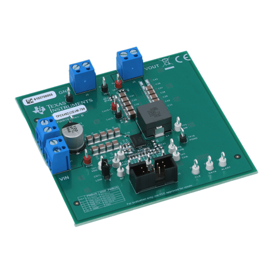
Page 8: Pwr-784Evm
Metal Ground Barrel Probe Tip and Barrel V Ripple Measurement Figure 3. Tip and Barrel Measurement TPS549D22EVM-784, 40-A Single Synchronous Step-Down Converter With SLUUBG4 – July 2016 Full Differential Sense and PMBus™ Submit Documentation Feedback Copyright © 2016, Texas Instruments Incorporated... -
Page 9: Evm And Usb Interface Adapter
PWR-784EVM www.ti.com Figure 4. EVM and USB Interface Adapter SLUUBG4 – July 2016 TPS549D22EVM-784, 40-A Single Synchronous Step-Down Converter With Full Differential Sense and PMBus™ Submit Documentation Feedback Copyright © 2016, Texas Instruments Incorporated... -
Page 10: List Of Test Points, Jumpers, And Switch
SMB_ALRT# Alert output for the PMBus interface. 2-pin jumper CNTL Shunts control pin to GND TPS549D22EVM-784, 40-A Single Synchronous Step-Down Converter With SLUUBG4 – July 2016 Full Differential Sense and PMBus™ Submit Documentation Feedback Copyright © 2016, Texas Instruments Incorporated... -
Page 11: Evm Configuration Using The Fusion Gui
EVM prior to launching the software so that the TPS549D22 installed is active and able to respond to the GUI and the GUI can recognize the device. SLUUBG4 – July 2016 TPS549D22EVM-784, 40-A Single Synchronous Step-Down Converter With Full Differential Sense and PMBus™ Submit Documentation Feedback... -
Page 12: Test Procedure
1. Reduce the load current to 0 A. 2. Reduce input voltage to 0 V. 3. Shut down the external fan if in use. 4. Shut down equipment. TPS549D22EVM-784, 40-A Single Synchronous Step-Down Converter With SLUUBG4 – July 2016 Full Differential Sense and PMBus™ Submit Documentation Feedback... -
Page 13: Performance Data And Typical Characteristic Curves
1.005 0.995 12 V 16 V 0.99 D002 Figure 6. Load Regulation of 1-V Output SLUUBG4 – July 2016 TPS549D22EVM-784, 40-A Single Synchronous Step-Down Converter With Full Differential Sense and PMBus™ Submit Documentation Feedback Copyright © 2016, Texas Instruments Incorporated... -
Page 14: Line Regulation
Figure 7. Line Regulation of 1-V Output Figure 8. PMBus V Step-Up = 0.6 V to 1.2 V at 0 A TPS549D22EVM-784, 40-A Single Synchronous Step-Down Converter With SLUUBG4 – July 2016 Full Differential Sense and PMBus™ Submit Documentation Feedback... -
Page 15: Pmbus V Out Step-Down = 1.2 V To 0.6 V At 0 A
Figure 9. PMBus V Step-Down = 1.2 V to 0.6 V at 0 A SLUUBG4 – July 2016 TPS549D22EVM-784, 40-A Single Synchronous Step-Down Converter With Full Differential Sense and PMBus™ Submit Documentation Feedback Copyright © 2016, Texas Instruments Incorporated... -
Page 16: Pmbus V Out Step-Up = 0.6 V To 1.2 V At 40 A
Performance Data and Typical Characteristic Curves www.ti.com Figure 10. PMBus V Step-Up = 0.6 V to 1.2 V at 40 A TPS549D22EVM-784, 40-A Single Synchronous Step-Down Converter With SLUUBG4 – July 2016 Full Differential Sense and PMBus™ Submit Documentation Feedback... -
Page 17: Pmbus V Out Step-Down = 1.2 V To 0.6 V At 40 A
Figure 11. PMBus V Step-Down = 1.2 V to 0.6 V at 40 A SLUUBG4 – July 2016 TPS549D22EVM-784, 40-A Single Synchronous Step-Down Converter With Full Differential Sense and PMBus™ Submit Documentation Feedback Copyright © 2016, Texas Instruments Incorporated... -
Page 18: Pmbus Multiple Commands
Performance Data and Typical Characteristic Curves www.ti.com Figure 12. PMBUS Multiple Commands TPS549D22EVM-784, 40-A Single Synchronous Step-Down Converter With SLUUBG4 – July 2016 Full Differential Sense and PMBus™ Submit Documentation Feedback Copyright © 2016, Texas Instruments Incorporated... -
Page 19: Transient Response
Figure 13. Transient Response of 1-V Output at 12 V , Transient is 8 A to 32 A, 2.5 A/µs SLUUBG4 – July 2016 TPS549D22EVM-784, 40-A Single Synchronous Step-Down Converter With Full Differential Sense and PMBus™ Submit Documentation Feedback Copyright © 2016, Texas Instruments Incorporated... -
Page 20: Output Ripple
Figure 14. Output Ripple and SW Node of 1-V Output at 12 V , 0-A Output Figure 15. Output Ripple and SW Node of 1-V Output at 12 V , 40-A Output TPS549D22EVM-784, 40-A Single Synchronous Step-Down Converter With SLUUBG4 – July 2016 Full Differential Sense and PMBus™ Submit Documentation Feedback... -
Page 21: Control On
Figure 17. 0.5-V Pre-bias start up from Control, 1-V Output at 12 V , 40-A Output SLUUBG4 – July 2016 TPS549D22EVM-784, 40-A Single Synchronous Step-Down Converter With Full Differential Sense and PMBus™ Submit Documentation Feedback Copyright © 2016, Texas Instruments Incorporated... -
Page 22: Control Off
11.7 Control Off Figure 18. Soft Stop from Control, 1-V Output at 12 V , 40-A Output TPS549D22EVM-784, 40-A Single Synchronous Step-Down Converter With SLUUBG4 – July 2016 Full Differential Sense and PMBus™ Submit Documentation Feedback Copyright © 2016, Texas Instruments Incorporated... -
Page 23: Thermal Image
11.8 Thermal Image Figure 19. Thermal Image at 1-V Output at 12 V , 40-A Output SLUUBG4 – July 2016 TPS549D22EVM-784, 40-A Single Synchronous Step-Down Converter With Full Differential Sense and PMBus™ Submit Documentation Feedback Copyright © 2016, Texas Instruments Incorporated... -
Page 24: Fusion Gui
Fusion GUI Figure 20. First Window at Fusion Launch Figure 21. Scan Finds Device Successfully TPS549D22EVM-784, 40-A Single Synchronous Step-Down Converter With SLUUBG4 – July 2016 Full Differential Sense and PMBus™ Submit Documentation Feedback Copyright © 2016, Texas Instruments Incorporated... -
Page 25: Software Launch Continued
Fusion GUI www.ti.com Figure 22. Software Launch Continued Figure 23. Software Launch Continued SLUUBG4 – July 2016 TPS549D22EVM-784, 40-A Single Synchronous Step-Down Converter With Full Differential Sense and PMBus™ Submit Documentation Feedback Copyright © 2016, Texas Instruments Incorporated... -
Page 26: First Screen After Successful Launch Configure: Limits And On/Off
VOUT Margin • Operation Figure 24. First Screen After Successful Launch Configure: Limits and On/Off TPS549D22EVM-784, 40-A Single Synchronous Step-Down Converter With SLUUBG4 – July 2016 Full Differential Sense and PMBus™ Submit Documentation Feedback Copyright © 2016, Texas Instruments Incorporated... -
Page 27: Configure: Frequency- Fs Configuration Pop-Up
Changing the frequency prompts a pop-up window with details of the options Figure 25). Figure 25. Configure: Frequency- FS Configuration Pop-up SLUUBG4 – July 2016 TPS549D22EVM-784, 40-A Single Synchronous Step-Down Converter With Full Differential Sense and PMBus™ Submit Documentation Feedback Copyright © 2016, Texas Instruments Incorporated... -
Page 28: Configure: Frequency- Fs Config Pop-Up With Change
When Store Config to NVM is selected, change is committed to nonvolatile memory and becomes the new default (Figure 26). Figure 26. Configure: Frequency- FS Config Pop-Up with Change TPS549D22EVM-784, 40-A Single Synchronous Step-Down Converter With SLUUBG4 – July 2016 Full Differential Sense and PMBus™ Submit Documentation Feedback Copyright © 2016, Texas Instruments Incorporated... -
Page 29: Configure: Store Config To Nvm
(Figure 27). Figure 27. Configure: Store Config to NVM SLUUBG4 – July 2016 TPS549D22EVM-784, 40-A Single Synchronous Step-Down Converter With Full Differential Sense and PMBus™ Submit Documentation Feedback Copyright © 2016, Texas Instruments Incorporated... -
Page 30: Change View Screen To Monitor Screen
Configure, Monitor and Status as needed (Figure 28). Figure 28. Change View Screen to Monitor Screen TPS549D22EVM-784, 40-A Single Synchronous Step-Down Converter With SLUUBG4 – July 2016 Full Differential Sense and PMBus™ Submit Documentation Feedback Copyright © 2016, Texas Instruments Incorporated... -
Page 31: System Dashboard
Selecting System Dashboard from mid-left screen adds a new window which displays system-level information (Figure 29). Figure 29. System Dashboard SLUUBG4 – July 2016 TPS549D22EVM-784, 40-A Single Synchronous Step-Down Converter With Full Differential Sense and PMBus™ Submit Documentation Feedback Copyright © 2016, Texas Instruments Incorporated... -
Page 32: Status Screen
Selecting Status from lower left corner shows the status of the controller (Figure 30). Figure 30. Status Screen TPS549D22EVM-784, 40-A Single Synchronous Step-Down Converter With SLUUBG4 – July 2016 Full Differential Sense and PMBus™ Submit Documentation Feedback Copyright © 2016, Texas Instruments Incorporated... -
Page 33: Store Configuration To Memory
Store Config to NVM button from the configure screen. It results in committing the current configuration to nonvolatile memory (Figure 31). Figure 31. Store Configuration To Memory SLUUBG4 – July 2016 TPS549D22EVM-784, 40-A Single Synchronous Step-Down Converter With Full Differential Sense and PMBus™ Submit Documentation Feedback Copyright © 2016, Texas Instruments Incorporated... -
Page 34: Pmbus Logging
See next screen (Figure 33). Figure 32. PMBus Logging TPS549D22EVM-784, 40-A Single Synchronous Step-Down Converter With SLUUBG4 – July 2016 Full Differential Sense and PMBus™ Submit Documentation Feedback... -
Page 35: Pmbus Log Details
(as Stop Logging). This file can rapidly grow in size, so caution is advised when using this function. Figure 33. PMBus Log Details SLUUBG4 – July 2016 TPS549D22EVM-784, 40-A Single Synchronous Step-Down Converter With Full Differential Sense and PMBus™ Submit Documentation Feedback Copyright © 2016, Texas Instruments Incorporated... -
Page 36: Evm Assembly Drawing And Pcb Layout
784EVM has a 2-oz. copper finish for all layers. Figure 34. PWR-784EVM Top Layer Assembly Drawing (Top View) Figure 35. PWR-784EVM Top Solder Mask (Top View) TPS549D22EVM-784, 40-A Single Synchronous Step-Down Converter With SLUUBG4 – July 2016 Full Differential Sense and PMBus™... -
Page 37: Pwr-784Evm Top Layer (Top View)
Figure 36. PWR-784EVM Top Layer (Top View) Figure 37. PWR-784EVM Inner Layer 1 (Top View) SLUUBG4 – July 2016 TPS549D22EVM-784, 40-A Single Synchronous Step-Down Converter With Full Differential Sense and PMBus™ Submit Documentation Feedback Copyright © 2016, Texas Instruments Incorporated... -
Page 38: Pwr-784Evm Inner Layer 2 (Top View)
EVM Assembly Drawing and PCB Layout www.ti.com Figure 38. PWR-784EVM Inner Layer 2 (Top View) Figure 39. PWR-784EVM Inner Layer 3 (Top View) TPS549D22EVM-784, 40-A Single Synchronous Step-Down Converter With SLUUBG4 – July 2016 Full Differential Sense and PMBus™ Submit Documentation Feedback... -
Page 39: Pwr-784Evm Inner Layer 4 (Top View)
Figure 40. PWR-784EVM Inner Layer 4 (Top View) Figure 41. PWR-784EVM Bottom Layer (Top View) SLUUBG4 – July 2016 TPS549D22EVM-784, 40-A Single Synchronous Step-Down Converter With Full Differential Sense and PMBus™ Submit Documentation Feedback Copyright © 2016, Texas Instruments Incorporated... -
Page 40: Pwr-784Evm Bottom Solder Mask (Top View)
EVM Assembly Drawing and PCB Layout www.ti.com Figure 42. PWR-784EVM Bottom Solder Mask (Top View) Figure 43. PWR-784EVM Bottom Overlay Layer (Top View) TPS549D22EVM-784, 40-A Single Synchronous Step-Down Converter With SLUUBG4 – July 2016 Full Differential Sense and PMBus™ Submit Documentation Feedback... -
Page 41: List Of Materials
TP16, TP17, TP20, TP21, TP22 TP2, TP3, TP4 Test Point, Multipurpose, Red, TH Red Multipurpose 5010 Keystone Testpoint SLUUBG4 – July 2016 TPS549D22EVM-784, 40-A Single Synchronous Step-Down Converter With Full Differential Sense and PMBus™ Submit Documentation Feedback Copyright © 2016, Texas Instruments Incorporated... - Page 42 RES, 1.50 k, 1%, 0.1 W, 0603 0603 RC0603FR-071K5L Yageo America 3.01 RES, 3.01 ohm, 1%, 0.125W, 0805 0805 CRCW08053R01FKEA Vishay-Dale TPS549D22EVM-784, 40-A Single Synchronous Step-Down Converter With Full SLUUBG4 – July 2016 Differential Sense and PMBus™ Submit Documentation Feedback Copyright © 2016, Texas Instruments Incorporated...
- Page 43 STANDARD TERMS AND CONDITIONS FOR EVALUATION MODULES Delivery: TI delivers TI evaluation boards, kits, or modules, including any accompanying demonstration software, components, or documentation (collectively, an “EVM” or “EVMs”) to the User (“User”) in accordance with the terms and conditions set forth herein. Acceptance of the EVM is expressly subject to the following terms and conditions.
- Page 44 FCC Interference Statement for Class B EVM devices NOTE: This equipment has been tested and found to comply with the limits for a Class B digital device, pursuant to part 15 of the FCC Rules. These limits are designed to provide reasonable protection against harmful interference in a residential installation.
- Page 45 【無線電波を送信する製品の開発キットをお使いになる際の注意事項】 開発キットの中には技術基準適合証明を受けて いないものがあります。 技術適合証明を受けていないもののご使用に際しては、電波法遵守のため、以下のいずれかの 措置を取っていただく必要がありますのでご注意ください。 1. 電波法施行規則第6条第1項第1号に基づく平成18年3月28日総務省告示第173号で定められた電波暗室等の試験設備でご使用 いただく。 2. 実験局の免許を取得後ご使用いただく。 3. 技術基準適合証明を取得後ご使用いただく。 なお、本製品は、上記の「ご使用にあたっての注意」を譲渡先、移転先に通知しない限り、譲渡、移転できないものとします。 上記を遵守頂けない場合は、電波法の罰則が適用される可能性があることをご留意ください。 日本テキサス・イ ンスツルメンツ株式会社 東京都新宿区西新宿6丁目24番1号 西新宿三井ビル 3.3.3 Notice for EVMs for Power Line Communication: Please see http://www.tij.co.jp/lsds/ti_ja/general/eStore/notice_02.page 電力線搬送波通信についての開発キットをお使いになる際の注意事項については、次のところをご覧くださ い。http://www.tij.co.jp/lsds/ti_ja/general/eStore/notice_02.page SPACER EVM Use Restrictions and Warnings: 4.1 EVMS ARE NOT FOR USE IN FUNCTIONAL SAFETY AND/OR SAFETY CRITICAL EVALUATIONS, INCLUDING BUT NOT LIMITED TO EVALUATIONS OF LIFE SUPPORT APPLICATIONS.
- Page 46 Notwithstanding the foregoing, any judgment may be enforced in any United States or foreign court, and TI may seek injunctive relief in any United States or foreign court. Mailing Address: Texas Instruments, Post Office Box 655303, Dallas, Texas 75265 Copyright © 2015, Texas Instruments Incorporated...
- Page 47 IMPORTANT NOTICE Texas Instruments Incorporated and its subsidiaries (TI) reserve the right to make corrections, enhancements, improvements and other changes to its semiconductor products and services per JESD46, latest issue, and to discontinue any product or service per JESD48, latest issue.
- Page 48 Mouser Electronics Authorized Distributor Click to View Pricing, Inventory, Delivery & Lifecycle Information: Texas Instruments TPS549D22EVM-784...
Need help?
Do you have a question about the TPS549D22EVM-784 and is the answer not in the manual?
Questions and answers