
Related Manuals for Pfeiffer Vacuum TPH 1801 P


Summary of Contents for Pfeiffer Vacuum TPH 1801 P
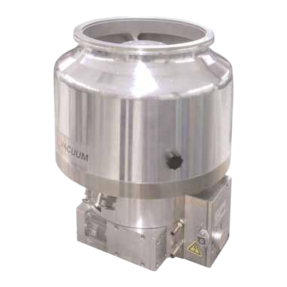
- Page 1 Betriebsanleitung • Operating Instructions Translation of the Original Operating Instructions Turbomolecular Pumps With Electronic Drive Unit TC 750 TPH 1801 P TPH 1801 P C...
-
Page 2: Table Of Contents
Index Page Page Safety Instructions......3 4.8. Operations With The DCU 001/DCU 600 or HPU 001 ............. 18 1.1. For Your Orientation ......... 3 4.9. Operations With The Remote Control Unit..19 1.2. Pictogram Definitions ........3 Venting Release (Optional) ......19 Understanding The Pumps .... -
Page 3: Safety Instructions
1. Safety Instructions ☞ Read and follow all instructions in this manual. 1.1. For Your Orientation ☞ Inform yourself regarding: – Hazards which can be caused by the pump; Instruction in the text – Hazards which can be caused by your system. ➡... -
Page 4: Understanding The Pumps
2.1. Main Features CAUTION filled with lubricant. Turbopumps TPH 1801 P/P C with the TC 750 form a complete When being fitted into or dismantled from a unit. Voltage is supplied by power supply (see Section 11. system, turbopumps may only be positioned as Accessories). -
Page 5: Improper Use
The following is regarded, inter alia, as improper: TPH 1801 P Standard version – The pumping of explosive gases. TPH 1801 P C Corrosive gas processes version – Operating the pumps in areas where there is a danger of explosion. -
Page 6: Installation
U U s s e e a a P P f f e e i i f f f f e e r r V V a a c c u u u u m m s s p p l l i i n n t t e e r r s s h h i i e e l l d d o o r r p p r r o o t t e e c c t t i i v v e e s s c c r r e e e e n n absorbed by the system and the high vacuum The use of a Pfeiffer Vacuum splinter shield or protective flange. - Page 7 Tightening torque: 10 Nm, 20 Nm, 38 ±3 Nm The components for installing the tuebopumps are special designs from Pfeiffer Vacuum Variant 2 - Stud screw with blind hole – The minimum strength of 170 N/mm of the flange material needs to be observed.
-
Page 8: Connecting The Fore-Vacuum Side
Permissible installation positions for the turbopump Recommendation: Dry backing pumps or rotary vane 11 Vacuum chamber vacuum pumps from the Pfeiffer Vacuum range. Connecting the backing pump All connections of the fore-vacuum line: With the usual small flange components or screwed hoses. -
Page 9: Connecting The Cooling Unit
3.4. Connecting The Cooling Unit Cooling with the Recycled Water Cooling Unit TZK (Accessory) The Turbopumps TPH 1801 P / P C have been designed to be water cooled as standard. Connection (cooling water connection please refer to Section Dirt traps are not permissible in the lines. -
Page 10: Connecting The Electronic Drive Unit Tc 750
3.5. Connecting The Electronic 3.6. Installing The Power Supply Drive Unit TC 750 Voltage may only be supplied with the Pfeiffer CAUTION Vacuum power supplies (please see Section 11. The turbopump and the Electronic Drive Unit PLEASE NOTE Accessories). TC 750 are connected and together form a The use of other power supplies requires the single unit. -
Page 11: Installing The Cover Plate For The Tc 750
3.7. Installing The Cover Plate For The TC Inserts and Screw fittings Screw Blank PG 16; for fitting disc The turbomolecular pump with integrated Electronic Drive cable Ø6 Unit TC 750 has an IP 30 protection class rating. Insert (scope of delivery When the turbopump is water cooled the enclosed water 1 piece E 153/8 1 piece E 153/11) -
Page 12: Connecting The Venting Valve
3.8. Connecting The Venting Valve 3.9. Connecting The Sealing Gas Valve The venting valve (see Section 11. Accessories) provides For protection pruposes the turbopumpe should be operated automatic venting in the event of a power failure and with sealing gas, particularly where corrosive and dusty switching off. -
Page 13: Connecting The Remote Control Unit
3.10. Connecting The Remote Control Pin occupancy remote plug Unit Remote control options for various functions are provided with the connection ”REMOTE” on the TC 750 via the 15 pole D-Sub connector. Shielded cable must be used. Shielding is on the plug side of the TC 750 connected to the TC 750 casing. The inputs 2 - 6 are activated by connecting them to the + 24V on pin 1 (active high) (please see Section 3.12. -
Page 14: Connecting The Serial Interface Rs 485
3.11. Connecting The Serial Connecting The RS 485 Interface RS 485 Connecting to a fixed bus system: An external operating component DCU 001/DCU 600 o o r r ➡ Connect all units with D+ (pin 5/RS 485) and HPU 001 o o r r – using a level converter – an external computer D- (pin7/RS 485) to the bus. -
Page 15: Connections Diagram
3.12. Connections Diagram TC 600 TC 750 n.c. +24 VDC* / max. 200 mA (supply voltage, DCU) n.c. n.c. RS 485 RS 485+/ (DO/RI) GND* (mass connection, DCU) RS 485- / (DO/RI) n.c. +24 VDC*/max. 50 mA Venting release Motor TMP Contact current: Pumping station max. -
Page 16: Operations
4. Operations 4.1. Filling In The Lubricant 4.2. Before Switching ON Turbopumps must be filled with lubricant before Sections 4.2 to 4.6. refer only to operating the pump in its CAUTION being operated. condition on delivery, without the DCU/HPU display and If possible fill in the lubricant in the fitting operating unit. -
Page 17: Switching On
4.3. Switching ON 4.4. Gas Type Dependent Operations ➡ Switch on the turbopump with switch S1 on the power Where high level gas loads and rotation speeds are involved, supply. the resulting friction subjects the rotor to the effect of great –... -
Page 18: Circulatory Lubrication
➡ Switch off both turbopump and backing pump on the bearing change must be carried out (please get in touch with Pfeiffer Vacuum Service). power supply at the same time with switch S1. Usability of the lubricant is 4 years without Where corrosive gas processes are involved, the sealing operation. -
Page 19: Operations With The Remote Control Unit
4.9. Operations With The Remote Control Standby Unit The pump can be operated optionally at 66% of its nominal rotation speed (standby ON) or at its nominal rotation speed Remote control operations can be performed via the connec- (standby OFF). tion with the designation “REMOTE”... -
Page 20: Monitoring Operations
5. Monitoring Operations 5.1. Operations Display Via LED 5.2. Turbopump Temperature Monitoring Certain operations modes of the turbopump and the TC 750 Where impermissible motor temperatures are involved or the can be ascertained via the two integrated LEDs located on temperature of the casing is too high, the motor current is the front panel of the TC 750. -
Page 21: What To Do In Case Of Breakdowns
• Enter 525 Hz for parameter 777 speed (Parameter 777) (see operating instruction PM 0547 BN “Pumping Operations With DCU”). If there is no DCU/HPU available contact Pfeiffer Vacuum Service. 1) Without a DCU or HPU inform Pfeiffer Vacuum Service to check the cause of trouble. -
Page 22: Service
➡ A copy of the completed declaration must accompany the unit; any additional copies must be sent to your local Pfeif- fer Vacuum Service Center. Please get in touch with your local Pfeiffer Vacuum represen- tatives if there are any questions regarding contamination. -
Page 23: Maintenance/Replacement
Electronic Drive Unit TC 750 yourself. sight glass is the lower edge of lubricant filler Please contact your local Pfeiffer Vacuum Service for all screw 71. other maintenance and service work. Ensure no mechanical forces act on the CAUTION Electronic Drive Unit TC 750. -
Page 24: Cleaning The Lubricant Pump
For cleaning the lubricant pump please contact your local power supply. Pfeiffer Vacuum Service Center. Order number for the Electronic Drive Unit TC 750, see Section 10. Spare Parts. 8.3. Replacing The Lubricant Pump... -
Page 25: Technical Data
9. Technical Data F F e e a a t t u u r r e e U U n n i i t t T T P P H H 1 1 8 8 0 0 1 1 P P T T P P H H 1 1 8 8 0 0 1 1 P P C C Connection nominal diameter: Inlet... -
Page 26: Dimensions Diagram
9.1. Dimensions Diagram TPH 1801 P / P C DN 200 ISO-F G1/8 271mm von HV-Flansch DN 200 ISO-F Ø 311 DN 40 ISO-KF Ø 200... - Page 27 TPH 1801 P / P C DN 200 ISO-K G1/8" DN 200 ISO-K Ø 311 (M6) DN 40 ISO-KF Ø 200...
-
Page 28: Spare Parts
10. Spare Parts Pos. Description Pieces Size Number Comments Ordering Quantity S S p p a a r r e e p p a a r r t t s s T T P P H H 1 1 8 8 0 0 1 1 P P / / P P C C Electronic Drive Unit TC 750 PM C01 713 see Section 8.4. -
Page 29: Accessories
11. Accessories Description Size Number Comments/ Order Quantity Operating Instructions C C o o m m p p o o n n e e n n t t s s f f o o r r c c o o o o l l i i n n g g Dirt trap R 3/8”... -
Page 30: Declaration Of Contamination
Declaration of Contamination of Vacuum Equipment and Components The repair and/or service of vacuum components will only be The manufacturer could refuse to accept any equipment carried out if a correctly completed declaration has been without a declaration. submitted. Non-completion will result in delay. This declaration can only be completed and signed by authorised and qualified staff: 1. -
Page 31: Declaration Of Conformity
"Electromagnetic Compatibility" 2004/108/EC . The agent responsible for compiling the technical documentation is Mr. Jörg Stanzel, Pfeiffer Vacuum GmbH, Berliner Straße 43, 35614 Aßlar. TPH 1801 P / TPH 1801 P C Guidelines, harmonised standards and national standards and specifications... - Page 32 Roots pumps Dry compressing pumps Leak detectors Valves Components and feedthroughs Vacuum measurement Gas analysis System engineering Service Pfeiffer Vacuum Technology AG · Headquarters/Germany Tel. +49-(0) 64 41-8 02-0 · Fax +49-(0) 64 41-8 02-2 02 · info@pfeiffer-vacuum.de · www.pfeiffer-vacuum.net...
Need help?
Do you have a question about the TPH 1801 P and is the answer not in the manual?
Questions and answers