
Subscribe to Our Youtube Channel
Related Manuals for Pfeiffer Vacuum TPU 2101 P


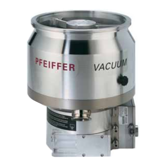
Summary of Contents for Pfeiffer Vacuum TPU 2101 P
- Page 1 Betriebsanleitung • Operating Instructions Turbomolecular Pumps With Electronic Drive Units TC 750 TPH 2101 P / PC TPU 2101 P / PC...
-
Page 2: Table Of Contents
Index Page Page Safety Instructions......3 4.8. Operations With The DCU 001/DCU 600 1.1. For Your Orientation ......... 3 or HPU 001 ............. 18 1.2. Pictogram Definitions ........3 4.9. Operations With The Remote Control Unit..19 Venting Release (Optional) ......19 Understanding The Pumps .... -
Page 3: Safety Instructions
1. Safety Instructions ☞ Read and follow all instructions in this manual. 1.1. For Your Orientation ☞ Inform yourself regarding: – Hazards which can be caused by the pump; Instruction in the text – Hazards which can be caused by your system. ➡... -
Page 4: Understanding The Pumps
The turbopumps must not be transported when CAUTION filled with lubricant. Turbopumps TPH/TPU 2101 P/P C with the TC 750 form a When being fitted into or dismantled from a complete unit. Voltage is supplied by power supply (see system, turbopumps may only be positioned as Section 11. -
Page 5: Improper Use
The following is regarded, inter alia, as improper: TPH/TPU 2101 P Standard version – The pumping of explosive gases. TPH/TPU 2101 P C Corrosive gas processes version – Operating the pumps in areas where there is a danger of explosion. -
Page 6: Installation
Use a Pfeiffer Vacuum splinter shield or protective mesh (see Section 4.1.). The use of a Pfeiffer Vacuum splinter shield or protective – If the turbopump is to be operated with the DCU 001 or mesh in the high vacuum flange protects the turbopump... - Page 7 Otherwise the turbomolecular pump may twist or tear off. The clamps, bolts, nuts and centering rings are special designs from Pfeiffer Vacuum Stud screw with blind hole – The minimum strength of 170 N/mm...
-
Page 8: Connecting The Fore-Vacuum Side
Permissible installation positions for the turbopump Recommendation: Dry backing pumps or rotary vane 11 Vacuum chamber vacuum pumps from the Pfeiffer Vacuum range. Connecting the backing pump All connections of the fore-vacuum line: With the usual small flange components or screwed hoses. -
Page 9: Connecting The Cooling Unit
3.4. Connecting The Cooling Unit Cooling with the Recycled Water Cooling Unit TZK (Accessory) The Turbopumps TPH/TPU 2101 P / P C have been designed to be water cooled as standard. Connection to the TZK (cooling water connection please refer to Section Dirt traps are not permissible in the lines. -
Page 10: Connecting The Electronic Drive Unit Tc 750
3.6. Connecting The Electronic 3.7. Installing The Power Supply Drive Unit TC 750 Voltage may only be supplied with the Pfeiffer CAUTION Vacuum power supplies (please see Section 11. The turbopump and the Electronic Drive Unit PLEASE NOTE Accessories). TC 750 are connected and together form a The use of other power supplies requires the single unit. -
Page 11: Installing The Cover Plate For The Tc 750
3.8. Installing The Cover Plate For The TC Inserts and Screw fittings Screw Blank PG 16; for fitting disc The turbomolecular pump with integrated Electronic Drive cable Ø6 Unit TC 750 has an IP 30 protection class rating. Insert (scope of delivery When the turbopump is water cooled the enclosed cover 1 piece E 153/8 1 piece E 153/11) -
Page 12: Connecting The Venting Valve
3.9. Connecting The Venting Valve 3.10. Connecting The Sealing Gas Valve The venting valve (see Section 11. Accessories) provides For protection pruposes the turbopumpe should be operated automatic venting in the event of a power failure and with sealing gas, particularly where corrosive and dusty switching off. -
Page 13: Connecting The Remote Control Unit
3.11. Connecting The Remote Control Unit Remote control options for various functions are provided with the connection "REMOTE" on the TC 750 via the 15-pole D-Sub- Connec- Shielding is on the plug side of tor. Shielded cable must be used. the TC 750 connected to the TC 750 casing. -
Page 14: Connecting The Serial Interface Rs 485
3.12. Connecting The Serial Connecting The RS 485 Interface RS 485 Connecting to a fixed bus system: An external operating component (DCU 001/DCU 600 o o r r ➡ Connect all units with D+ (pin 5/RS 485) and HPU 001) o o r r an external computer can be connected via the D- (pin7/RS 485) to the bus. -
Page 15: Connections Diagram
3.13. Connections Diagram TC 600 TC 750 n.c. +24 VDC* / max. 200 mA (supply voltage, DCU) n.c. n.c. RS 485 RS 485+/ (DO/RI) GND* (mass connection, DCU) RS 485- / (DO/RI) n.c. +24 VDC*/max. 50 mA Venting release Motor TMP Contact current: Pumping station max. -
Page 16: Operations
4. Operations 4.1. Filling In The Lubricant 4.2. Before Switching ON Turbopumps must be filled with lubricant before Sections 4.2 to 4.6. refer only to operating the pump in its CAUTION being operated. condition on delivery, without the DCU/HPU display and If possible fill in the lubricant in the fitting operating unit. -
Page 17: Switching On
4.3. Switching ON – "Gas Mode 0" for gases with molecular mass ≥ 40 as, for example, Argon; ➡ Switch on the turbopump with switch S1 on the power – "Gas Mode 1" for all lighter gases. supply. – Once the self test has been successfully completed on the Works setting: “Gas Mode 0”... -
Page 18: Circulatory Lubrication
The valve cross-section for a venting rate of 15 mbar/s must be compatible with the size of the vacuum chamber. Where small vacuum chambers are involved, the Pfeiffer Vacuum Venting Valve TVF 005 can be used for first stage venting. ➡ Shut off water supply. -
Page 19: Operations With The Remote Control Unit
4.9. Operations With The Remote Control Standby Unit The pump can be operated optionally at 66% of its nominal rotation speed (standby ON) or at its nominal rotation speed Remote control operations can be performed via the connec- (standby OFF). tion with the designation “REMOTE”... -
Page 20: Monitoring Operations
5. Monitoring Operations 5.2. Turbopump Temperature Monitoring 5.1. Operations Display Via LED Where impermissible motor temperatures are involved or the Certain operations modes of the turbopump and the TC 750 temperature of the casing is too high, the motor current is can be ascertained via the two integrated LEDs located on reduced. -
Page 21: What To Do In Case Of Breakdowns
(Parameter 777) (see operating instruction PM 0547 BN “Pumping Operations With DCU”). If there is no DCU/HPU available contact Pfeiffer Vacuum Service . 1) Without a DCU or HPU inform Pfeiffer Vacuum Service to check the cause of trouble. -
Page 22: Service
➡ A copy of the completed declaration must accompany the unit; any additional copies must be sent to your local Pfeif- fer Vacuum Service Center. Please get in touch with your local Pfeiffer Vacuum represen- tatives if there are any questions regarding contamination. -
Page 23: Maintenance/Replacement
Electronic Drive Unit TC 750 yourself. ➡ Unscrew lubricant filler screw 71. Using the syringe provi- Please contact your Pfeiffer Vacuum Service for all other ded inject approximately 40 ml of lubricant as per the type maintenance and service work. -
Page 24: Cleaning The Lubricating Pump
For cleaning the lubricant pump please contact your local power supply. Pfeiffer Vacuum Service. Remove the Electronic Drive Unit TC 750 from the turbopump as follows: 8.3. Replacing The Lubricant Pump ➡... -
Page 25: Technical Data
9. Technical Data F F e e a a t t u u r r e e U U n n i i t t T T P P H H 2 2 1 1 0 0 1 1 P P T T P P U U 2 2 1 1 0 0 1 1 P P T T P P H H 2 2 1 1 0 0 1 1 P P C C T T P P U U 2 2 1 1 0 0 1 1 P P C C... -
Page 26: Dimensions Diagram
9.1. Dimensions Diagram Diameter DN 200 ISO-K 374.5 DN 250 ISO-KF 354.5 Cooling water connection DN 250 CF-F G1/8” DN 250 CF-F (Insert screws only from the DN 250 ISO-K Ø311 direction of the counter-flange or fit with stud bolts) DN 200 ISO-K 142.4 Ø200... -
Page 27: Spare Parts
Pos. Description Pieces Size Number Comments Ordering Quantity Spare parts TPH/TPU 2101 P / TPH/TPU 2101 P C Electronic Drive Unit TC 750 PM C01 713 see Section 8.4. Remote plug P 0920 668 E Seal ring for water connections... -
Page 28: Accessories
11.Accessories D D e e s s c c r r i i p p t t i i o o n n S S i i z z e e N N u u m m b b e e r r C C o o m m m m e e n n t t s s / / O O r r d d e e r r Q Q u u a a n n t t i i t t y y O O p p e e r r a a t t i i n n g g I I n n s s t t r r u u c c t t i i o o n n s s... -
Page 29: Declaration Of Contamination
Declaration of Contamination of Vacuum Equipment and Components The repair and/or service of vacuum components will only be The manufacturer could refuse to accept any equipment carried out if a correctly completed declaration has been without a declaration. submitted. Non-completion will result in delay. This declaration can only be completed and signed by authorised and qualified staff: 1. -
Page 31: Manufacturer´s Declaration
Directive 73/23/EEC. Produkt/Product: TPH 2101 P / TPH 2101 PC TPU 2101 P / TPU 2101 PC Angewendete Richtlinien, harmonisierte Normen und angewendete, nationale Normen: Guidelines, harmonised standards, national standards in which have been applied: E E N N 1 1 2 2 1 1 0 0 0 0 - - 1 1... - Page 32 Roots pumps Dry compressing pumps Leak detectors Valves Components and feedthroughs Vacuum measurement Gas analysis System engineering Service Pfeiffer Vacuum Technology AG · Headquarters/Germany Tel. +49-(0) 64 41-8 02-0 · Fax +49-(0) 64 41-8 02-2 02 · info@pfeiffer-vacuum.de · www.pfeiffer-vacuum.net...
Need help?
Do you have a question about the TPU 2101 P and is the answer not in the manual?
Questions and answers