
Related Manuals for JUMO hydroTRANS S20


Summary of Contents for JUMO hydroTRANS S20
- Page 1 JUMO hydroTRANS S20 Humidity and temperature transmitter with CO module, wall-mounted version Operating Manual 90704212T90Z001K000 V1.00/EN/2024-05-28...
- Page 2 Further information and downloads qr-907042-en.jumo.info...
-
Page 3: Table Of Contents
Table of contents Table of contents About this documentation ........6 Purpose. - Page 4 Table of contents Operation ........... . .18 Display elements.
- Page 5 Table of contents Shutdown ........... . .30 13.1 Dismounting .
-
Page 6: About This Documentation
About this documentation 1 About this documentation Purpose This documentation is part of the device and includes all information to ensure that it is used safely and as intended across all phases of the product lifecycle. If you do not follow the documentation and safety information, this may result in risk to life and damage to property due to improper use. -
Page 7: Safety
Safety 2 Safety Intended use The humidity and temperature transmitter monitors the ambient air quality. The device is suitable for wall mounting in indoor areas and weather-proofed outdoor areas. The documentation is part of the device. The device is only intended for use according to this documen- tation. -
Page 8: Description
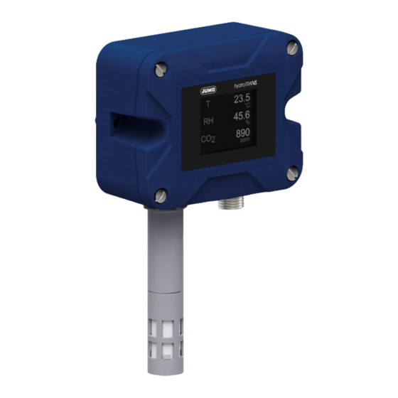
Description 3 Description Structure Front view Housing rear Probe Housing front Filter cap Display (TFT display) M12 plug connector Function Measurand Function principle Relative humidity Capacitive measurement technology Temperature Semiconductor measurement technology Carbon dioxide (CO Photoacoustic measurement technology The process values of the measurands can be displayed on the display and issued to a higher-level sys- tem via the interfaces. -
Page 9: Nameplate
3 Description Nameplate Housing rear (Rear view) Order code Fabrication number Manufacturer and address Power consumption UKCA identification marking Part no. CE identification marking Protection type according to DIN EN 60529 Data Matrix code Disposal Voltage supply (DC) Observe device documentation! Scope of delivery Device in the ordered version Brief instructions... -
Page 10: Technical Data
Technical data 4 Technical data Electrical safety Requirements DIN EN IEC 61010-1:2020 The device must be equipped with an electrical circuit that meets the require- ments for "Limited-energy circuits". Electrical data Voltage supply DC 18 to 30 V, PELV Current consumption ≤... -
Page 11: Interfaces
≤ 5 m 4.4.2 Function Transfer of process data, configuration data, and device information, voltage supply via PoDL Communication Via end device and JUMO Cloud, via Modbus master SPE standard 10BASE-T1L Transmission protocol Integrated JUMO Cloud gateway, Modbus TCP Data transfer rate... -
Page 12: Display
4 Technical data Display Type TFT display Size Display range 35.04 mm × 28.03 mm Screen size (diagonal) 1.77″ Resolution 128 × 160 RGB Brightness 11 levels (configurable) Environmental influences Admissible ambient temperature -10 to +60 °C Admissible storage temperature -30 to +60 °C Protection type DIN EN 60529... -
Page 13: Dimensions
4 Technical data Dimensions... -
Page 14: Mounting
Mounting 5 Mounting Mounting the device Aids Cross-headed screwdriver Material 2 Fastening screws (socket button self-tapping screw 4.8 × 38) Requirements: • The mounting holes have been drilled. Procedure: 1. Mount the device with the fas- tening screws (1). Electrical connection: Seite 15... -
Page 15: Electrical Connection
Electrical connection 6 Electrical connection Connection elements Device M12 plug connector 6.1.1 Terminal assignment M12 plug connector Designation Description Assignment RxTx+/PoDL+ 1 WH (white) RxTx-/PoDL- 2 BU (blue) Device Connecting cable... -
Page 16: Connection Diagram
6 Electrical connection Connection diagram Analog outputs Current output Voltage output ≤ 500 Ω... -
Page 17: Connecting The Device
6 Electrical connection Connecting the device Material Connecting cable, "Electrical data ", Page 10 Requirements: • The system has been de-energized and secured against being switched on again. • The connections for the voltage supply and signal processing have been correctly prepared. Procedure: 1. -
Page 18: Operation
Operation 7 Operation Display elements 7.1.1 Startup display The startup display appears as soon as the voltage supply to the device is established. The startup dis- play switches to the process value display after approximately five seconds. Pos. Designation Description Startup display Shows the device name. -
Page 19: Setup Program
Setup program 8 Setup program The setup program is used to configure the devices and can be downloaded free of charge from the product website of the manufacturer. The configuration data that is created can be saved in a file and transferred between the device and set- up program. -
Page 20: Configuration
Configuration 9 Configuration The default settings are shown in bold in the following tables. File info In the File info menu you can enter information about the configuration file. System data Parameter Value Description Language German, English, French, Span- National language for the device texts of the process display. -
Page 21: Measurand Correction
9 Configuration Measurand correction Parameter Value Description Relative humidity Offset – Temperature Offset – Carbon dioxide Offset, Automatic self-calibration – Relative humidity Parameter Value Description Offset Input range: Process value correction, also af- -15 to 15 % (0.0) fects the calculated values. Temperature Parameter Value... -
Page 22: Cloud Gateway
9 Configuration Cloud Gateway Parameter Value Description Connection to the cloud Inactive, Active – Online parameters This function requires an active connection between the setup program and device. Parameter Description Hardware/software Version of the device hardware and software Measurands Test of sensor functions Display Test of color reproduction Calibration constants... -
Page 23: Troubleshooting
Troubleshooting 10 Troubleshooting 10.1 Process value error With error messages in line with the NAMUR classification NE 107, process value errors are supple- mented by symbols and a two-line message (alternating with the process display). Error message Possible cause Remedy <<<<<... -
Page 24: Error Messages In Line With Namur
10 Troubleshooting... -
Page 25: Modbus Address Tables
Modbus address tables 11 Modbus address tables All data types are transmitted in big-endian format according to Modbus standard. 11.1 Version and fabrication number Modbus PDU Data type Number of Access Data Coding address Modbus registers 0x0015 String Software version number –... -
Page 26: Display
11 Modbus address tables 11.2.2 Display Modbus PDU Data type Number of Access Data Coding address Modbus registers 1100 0x044C Selector Value 1st line Analog selector , page 28 1106 0x0452 Selector Value 2nd line 1112 0x0458 Selector Value 3rd line 1118 0x045E Integer... -
Page 27: Network Settings
11 Modbus address tables 11.2.5 Network settings Modbus PDU Data type Number of Access Data Coding address Modbus registers 1700 0x06A4 Selection Method 0: Manually 1: Automatically 1701 0x06A5 String IP address – 1709 0x06AD String Subnet mask – 1717 0x06B5 String Standard gateway... -
Page 28: Error Messages Modbus
11 Modbus address tables 11.2.9 Error messages Modbus Modbus PDU Data type Number of Access Data Coding address Modbus registers 6400 0x1900 Boolean General error – 6401 0x1901 Boolean Configuration faulty – 6402 0x1902 Boolean Calibration faulty – 6403 0x1903 Boolean Device not calibrated –... -
Page 29: Maintenance And Cleaning
Maintenance and cleaning 12 Maintenance and cleaning 12.1 Replacing filter cap Requirements: • The system has been de-energized and secured against being switched on again. • A clean and dry storage location has been prepared. Procedure: 1. CAUTION! Exposed sensor board (3). -
Page 30: Shutdown
Shutdown 13 Shutdown 13.1 Dismounting Aids Screwdriver Requirements: • The system has been de-energized and secured against being switched on again. Procedure: 1. Loosen the union nut on the connecting cable. 2. Remove the connecting cable. 3. Undo the fastening screws. 4. -
Page 31: Spare Parts And Accessories
Spare parts and accessories 14 Spare parts and accessories Designation Part no. USB cable, A to Micro-B 00616250 JUMO hydroTRANS setup program 00775170 Plastic membrane filter (Ø = 18 mm) 30048149 SPE network switch 4-port (10BASE-T1L) 30062113 SPE network switch 8-port (10BASE-T1L) -
Page 32: Open-Source Software
Insofar as the respectively applicable license terms justify a claim on the provision of source code or oth- er information, JUMO GmbH & Co. KG will provide the source code and the license texts on a conven- tional data carrier at the cost incurred for the provision of the data carrier. - Page 34 JUMO GmbH & Co. KG JUMO UK LTD JUMO Process Control, Inc. Street address: JUMO House 6724 Joy Road Moritz-Juchheim-Straße 1 Temple Bank, Riverway East Syracuse, NY 13057, USA 36039 Fulda, Germany Harlow, Essex, CM20 2DY, UK Delivery address: Phone:...
Need help?
Do you have a question about the hydroTRANS S20 and is the answer not in the manual?
Questions and answers