Table of Contents
Advertisement
Quick Links
Doc. no. TQ1230001-OM102-A
PRODUCT NAME
Vacuum gripper unit
MODEL / Series / Product Number
ZXP7
41-
-X1
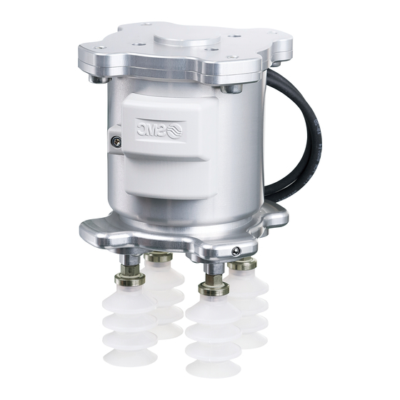
The outward appearance showed on this manual is an example of the vacuum gripper unit with
suction cups which is indicated by the product number: ZXP7A41-ZPB25JS-X1. Refer to the suction
cup catalog for the detail of other applicable suction cups.
Advertisement
Table of Contents

Subscribe to Our Youtube Channel
Related Manuals for SMC Networks ZXP7 41-X1 Series


Summary of Contents for SMC Networks ZXP7 41-X1 Series
- Page 1 Doc. no. TQ1230001-OM102-A PRODUCT NAME Vacuum gripper unit MODEL / Series / Product Number ZXP7 The outward appearance showed on this manual is an example of the vacuum gripper unit with suction cups which is indicated by the product number: ZXP7A41-ZPB25JS-X1. Refer to the suction cup catalog for the detail of other applicable suction cups.
-
Page 2: Table Of Contents
Contents Safety instructions…………………………………………………………………………………………………..2 1. Parts included in the package ....................... 6 2. Names of Parts of the Product ......................7 3. Specifications ............................8 3.1. Specifications ..........................8 3.2. Flow rate / Exhaust characteristics .................... 9 3.3. How to calculate theoretical lifting force .................. 10 3.4. -
Page 3: Safety Instructions
Safety Instructions These safety instructions are intended to prevent hazardous situations and/or equipment damage. These instructions indicate the level of potential hazard with the labels of “Caution,” “Warning” or “Danger.” They are all important notes for safety and must be followed in addition to International Standards (ISO/IEC) , and other safety regulations. - Page 4 Safety Instructions Caution The product is provided for use in manufacturing industries. The product herein described is basically provided for peaceful use in manufacturing industries. If considering using the product in other industries, consult SMC beforehand and exchange specifications or a contract if necessary. If anything is unclear, contact your nearest sales branch.
- Page 5 ■Explanation of Symbols S ym b o l Definition Things you must not do. Instructions are provided as a drawing or sentence next to the symbol. Things you must do Instructions are provided as a drawing or sentence next to the symbol. ■Operator 1.
- Page 6 Caution Do not touch the terminals and connectors while the power is on. Otherwise electric shock, malfunction or damage to the switch can result. Do not touch Perform sufficient trial run. Otherwise, injury or damage to the system can result due to suction failure depending on the conditions of the suction of the workpiece or the pressure switch settings.
-
Page 7: Parts Included In The Package
1. Parts included in the package Robot mounting flange 1 pc. Parallel pin (6x10): 1 pc. Hexagon socket head cap screw (M6x10): 8 pcs. Plug: 4 pcs. Part No. M-3P (When “cup mounting flange shape” is selected.) Vacuum gripper unit: 1 pc. Used for decreasing the number of suction cups. -
Page 8: Names Of Parts Of The Product
2. Names of Parts of the Product Parallel pin (6x10) Robot mounting flange (Compliant with “ISO9409-1-50-4-M6”) Hexagon socket head cap screw (M6x10) Air pressure supply port Applicable tubing O.D.: Φ6 Cover Hexagon socket head cap screw (M6x10) M8 Connector cables Parallel pin (6x10) O-ring Cup mounting flange... -
Page 9: Specifications
3. Specifications 3.1. Specifications ■Product specifications Mechanical interface standard Compliant with “ISO9409-1-50-4-M6” Fluid 5 to 50 Operating temperature range[°C] M8/8PIN (Male), M8/5PIN (Male) Connector type ZXP7N41-X1 ZXP7A41-X1 Weight[g] Common Example) note1) ZXP7A41-ZPB25JS-X1 Max. workload [kg] Note2) Impact / Vibration resistance [m/s 150 / 30 Note3) Air supply port(P) -
Page 10: Flow Rate / Exhaust Characteristics
3.2. Flow rate / Exhaust characteristics ■Flow rate / Exhaust characteristics. The flow rate characteristics correspond to the standard supply pressure (0.5MPa). Suction flow [L/min(ANR)] Exhaust characteristics Flow rate characteristics * The actual suction flow at the point of suction varies depending on the piping conditions to the vacuum port. ■How to read the flow rate characteristics Graph Flow rate characteristics are expressed in ejector vacuum pressure and suction flow. -
Page 11: How To Calculate Theoretical Lifting Force
3.3. How to calculate theoretical lifting force This manual shows how to calculate theoretical lifting force only. Refer to the catalog of suction cups for further detail of suction cup selection method. ■How to calculate theoretical lifting force The theoretical lifting force of a cup can be found by calculation or from the theoretical lifting force table. Calculation W: Lifting force [N] P: Vacuum pressure [kPa]... -
Page 12: How To Order
3.4. How to order ■Vacuum Gripper unit Suction cup part 1 Refer to below table about a aplicable cup. 41 - ZP U N - Vacuum gripper unit 2) Cup mounting flange 1) Unit size 3 ) Applicable manufacturer 4) Suction cup series 5) Cup diameter 6) Cup form 7) Material... -
Page 13: Mounting
4. Mounting 4.1. Mounting ■Mounting procedure 1) Confirm the gasket seal on the adapter, then mount 4 cups with adapter to the vacuum gripper unit. (Tightening torque: 1N・m or tighten for 45 degrees using a spanner after tightening by hand) 2) Mount parallel pin to the robot flange pin hole. - Page 14 Caution Vacuum gripper direction can be changed in 90-degree increments when attached to a robot. At that time, install it in the direction of the lower figure. (90-degree between the camera module and the cover of the vacuum unit.) Camera module cover -13- No.
-
Page 15: Wiring
4.2. Wiring ■Mount the M8 connector cables Mount the M8 connector cable to the M8 connector (female) of the robot tool flange. *Do not energize while securing the connector. *Check that the connector is not loose M8/8PIN M8/5PIN M8 connector cables (Male) ■M8/8PIN Wire Function... -
Page 16: Piping
4.3. Piping ■Tube Connect a tube (applicable tube O.D. Ø6) to the air pressure supply (P) port. (Refer to P.29 Installation of Tubing.) To remove the tube, push the release button and pull out the tube. Release Button Air pressure supply (P) port Applicable tubing O.D.: Φ6 -15- No. -
Page 17: Tmcomponent
4.4. TMComponent TMComponent is an independent software package for the robot applications and you need to import the software package to use in TMflow (robot software) directly. Here is the list of the SMC Vacuum Gripper Unit TMComponents. VacuumSensor_SMC_ZXP_***_Adsorb (The gripper adsorbs in vacuum to grip a workpiece) VacuumSensor_SMC_ZXP_***_Release (The gripper blows off to release a workpiece) Note) *** is the version number starting from 001. - Page 18 Configure gripper button The user can assign SMC Gripper Components to the Gripper button and use to adsorb and release the workpiece. Click the triple bar icon and go back to the main menu. Then select Setting icon. Click on Gripper Button icon. In the Gripper Button window, tick the Using Customized Component radio button and select the Component you want to assign to either one of the Gripper actions.
- Page 19 Use TMComponent Component Adsorb node This component is used to grip a part by vacuum absorption. Success : Adsorbs in vacuum and move to the next operation without checking the vacuum pressure level when Adsorb_and_ CheckVacuumLevel is set to false. Adsorbs in vacuum and if the vacuum pressure level is reached to set value meaning a workpiece is gripped, move to the next operation when Adsorb_and_CheckVacuumLevel is set to true.
- Page 20 Component Release node This component is used to release a workpiece by blowing off. The vacuum pressure level is not checked in this case. Success : Blow off and move to the next operation Wrong_value : The set value of BlowOffTime_Setting is out of range Function Type Default...
-
Page 21: Dimensions
5. Dimensions 5.1. Vacuum gripper unit * Cup distance is changeable. -20- No. TQ1230001-OM102-A... -
Page 22: Center Of Gravity
5.2. Center of gravity (ZXP7A41-ZPB25JN-X1) Center of gravity 0.01 0.68 56.48 -21- No. TQ1230001-OM102-A... -
Page 23: Suction Cup With Adapter
5.3. Suction cup with adapter *It is shown here for representative model only. See the suction cup catalog for the other models. -22- No. TQ1230001-OM102-A... - Page 24 Note1) “D” and (st) indicate the reference value during gripping at vacuum pressure: -85[kPa]. -23- No. TQ1230001-OM102-A...
-
Page 25: How To Change The Number Of Cups
6. How to change the number of cups 6.1 Change to 1 cup (with flange) 1. Removal of the cup. (1) Remove the suction cup with adapter from plate B using a spanner. (2) Loosen the bolt (M4 x 8), then remove plate B from plate A. Be careful not to lose the O-ring. -
Page 26: Change To 1 Cup (Without Flange)
6.2 Change to 1 cup (without flange) *No mesh in the vacuum (V) port. If the mesh is necessary in the vacuum (V) port, use the vacuum gripper unit with cup mounting flange. 1. Removal of the cup mounting flange (1) Loosen the bolt (M6 x 10), then remove the cup mounting flange. -
Page 27: Change To 2 Cups
6.3 Change to 2 cups 1. Removal of the suction cup with adapter (1) Remove the suction cup with adapter from the plate B using a spanner. (2) Loosen the bolt (M4 x 8), then remove plate B from plate A. Be careful not to lose the O-ring. -
Page 28: Maintenance
7.Maintenance Implement the maintenance and check shown below in order to use the vacuum gripper unit safely and in an appropriate way for a long period of time. 7.1. Maintenance for vacuum gripper unit Caution 1) Check before and after the maintenance work When the product is to be removed, turn off the power supply, and be sure to cut off the supply pressure and exhaust the compressed air. -
Page 29: Maintenance For Suction Cup
7.2. Maintenance for suction cup Caution 1) Suction cups are disposable. Replace them on a regular basis. Continued use of suction cups will cause wear and tear on the gripping surface, and the exterior dimensions will gradually get smaller and smaller. As the cups’ diameter gets smaller, their lifting force will decrease, though gripping will still remain possible. -
Page 30: Precautions
8.Precautions 8.1 Air supply Warning ■Use clean air. It is recommended to use compressed air which purity class is 2:6:3 of ISO8573-1:2010. Supply air containing foreign matter, water, oil, condensate, etc., can cause malfunction of the supply valve and release valve. So, install air preparation equipment on the upstream side of the product (refer to the piping example below) and perform maintenance periodically to control the supply air properly. - Page 31 ■Piping Caution 1) Preparation before piping Before piping, perform air blow (flushing) or cleaning to remove any cutting chips, cutting oil, dust, etc. from the piping. 2) Installation of tubing ・Cut the tubing perpendicularly, being careful not to damage the outside surface. Use an SMC tube cutter TK- 1,2,3.
- Page 32 ■Workpiece If water drops or dust are attached on the workpiece surface, they may go into the vacuum ejector and may cause the low vacuum performance. Also when workpieces are permeable, there is a case that sufficient lifting force cannot get. In such cases, it is necessary to perform a suction test to check the compatibility to your application before actual usage.
-
Page 33: Suction Cup Precautions
8.3 Suction cup precautions ■Design Warning 1) In cases where the workpieces are heavy or dangerous objects, etc., take measures to address a possible loss of gripping force (installation of a drop prevention guide, etc.). In the case of transportation by vacuum gripping using suction cups, the gripping force is lost when there is a drop in vacuum pressure. - Page 34 ■Gripping This product has 4 pneumatically connected cups per ejector. If one cup fails to operate, all other cups cannot grip the object. Safety measures needs to be taken to prevent falling of workpiece during transfer of the object. When gripping with cups which do not grip object is required, connect the vacuum saving valve, ZP2V series (Applicable model: ZP2V-B6-05).
- Page 35 Theoretical lifting force of vacuum cup diameter 32mm with ZP2V-B06-05 at supply pressure 0.5 MPa Vacuum pressure Theoretical lifting force Horizontal lifting force [N](Safety factor 1/4) [kPa] 1 cup gripping 40.2 2 cups gripping 53.8 13.4 3 cups gripping 58.7 14.6 (Calculated by “W = P X S, S = π・r , r = Φ...
-
Page 36: Trouble Shooting
9.Trouble shooting Condition & Description of Contributing factor Countermeasure improvement Recheck the relationship between workpiece mass Gripping area is small. and lifting force. (Lifting force is lower than the - Use a suction cup with a large gripping area. workpiece mass.) - Increase the quantity of suction cups. - Page 37 Revision history Rev. A: P. 15 Circuit modified. P. 20 Appearance dimension change P. 22 Add to Center of gravity P. 26 Revise errors. P. 34 Add to trouble shooting 4-14-1, Sotokanda, Chiyoda-ku, Tokyo 101-0021 JAPAN Tel: + 81 3 5207 8249 Fax: +81 3 5298 5362 https://www.smcworld.com Note: Specifications are subject to change without prior notice and any obligation on the part of the manufacturer.
Need help?
Do you have a question about the ZXP7 41-X1 Series and is the answer not in the manual?
Questions and answers