Table of Contents
Advertisement
Quick Links
Advertisement
Table of Contents

Subscribe to Our Youtube Channel
Related Manuals for HW Group HWg-Ares 10


Summary of Contents for HW Group HWg-Ares 10
- Page 1 HWg-Ares 10/12 – User manual...
-
Page 2: Safety Information
The manufacturer warrants the device only if it is powered by the supplied power adapter or an approved power supply. If you have any problems with installing or operating the device, please contact technical support: HW group s. r. o. http://www.hw-group.com Formanská 296 E-mail: support@HWg.cz... -
Page 3: Table Of Contents
Table of contents Safety information Basic features Description of connectors and connections Specifications First steps Inputs Sensors Email Advanced settings General Inputs Outputs Sensors Time SMS template Email Email templ. GPRS / Internet Portal Logger System Connecting to the Portal How to reduce operating costs Special functions Text message commands... -
Page 4: Basic Features
Basic features • Quadband modem GSM 850 / 900 / 1800 / 1900 MHz • Number of 1-Wire sensors: • Ares 10 – 3 • Ares 12 – 14 • External antenna • Support for PIN-protected SIM • Alarm alerts •... -
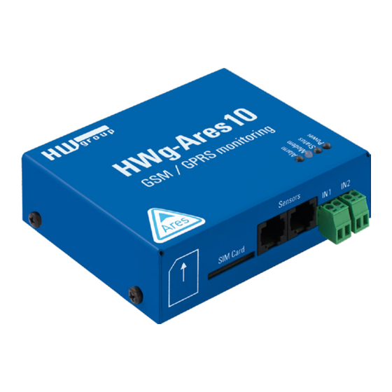
Page 5: Description Of Connectors And Connections
Description of connectors and connections LED indicators Alarm (red) • – indicates alarm status. One or more sen- sors read outside of the allowed range, or an alarm at one or more inputs (2× Digital Inputs or external power supply indication). •... -
Page 6: Specifications
Specifications GSM / GPRS Quad-Band 850/900/1800/1900 MHz, GPRS class 10/8 Compliant to GSM Interface phase 2/2 + – Class 4 (2 W @ 850 / 900 MHz) – Class 1 (1 W @ 1800 / 1900 MHz) Supported protocols IP: TCP , UDP , HTTP , SNTP , SMTP , HWg-PUSH Sensors Type HWg original accessories: 1-Wire &... -
Page 7: First Steps
First steps Connect Ares to PC with an USB cable and open the ARES disk that appears. Double-click the AresConf application to start it. The General tab appears and shows the device status: General This tab gives information about sensors and digital inputs, together with graphical symbols for quick overview. -
Page 8: Inputs
Inputs Use this tab to configure basic properties of digital inputs: Clear All Counters • – sets all counters to zero value. Save • – saves all changes. Sensors Use this tab to configure basic properties of sensors: • – removes the sensor from the list (e.g. when the sensor is disconnected). If the sensor remains physically connected, it will be detected again when the Ares unit is restarted. -
Page 9: Sms
Use this tab to configure alarm text message (SMS) recipients. Each recipient phone number is also authorized to request information from Ares 12 by dialing the unit's phone number and to send SMS commands without a password (see Advanced settings). Recipient 1-5 •... -
Page 10: Email
Email Use this tab to configure alarm e-mail recipients and parameters. • Recipient 1-5 – e-mail addresses of recipients for alarm e-mails. SMTP Server • – IP address or host name of the SMTP server to use for sending e-mail.* SMTP Port •... -
Page 11: Advanced Settings
Advanced settings Advanced settings are enabled by pressing the Advanced Mode button. General This tab gives information about sensors and digital inputs, together with graphical symbols for quick overview. • Device name – useful for sorting in higher-level systems, or to tell apart several Ares units. •... - Page 12 • Dialing... – connection to the carrier is being dialed (necessary to establish GPRS connecti- on). This information should not appear for more than 20 s. Otherwise, it indicates a modem fault (see Troubleshooting). • Configuring Internet... – internet connection is being configured (reading IP parameters). •...
-
Page 13: Inputs
Inputs Use this tab to configure basic and advanced properties of digital inputs: State • – graphical information about input states (same as on the General tab). • – unique sensor ID. Name • – sensor name, used for easier overview and for further processing in other systems. Value •... -
Page 14: Outputs
Outputs It is possible to connect the External Outputs module* via the 1-Wire UNI interface to the Ares 12 device. This module provides 4 NO/NC relay outputs with maximum load up to 1 A / 30 V DC or up to 0,5 A / 50 V AC. •... -
Page 15: Sensors
Delete All Outputs • – deletes all discovered outputs. Save • – saves all changes. *Optional accessory. Available as of 06/2017. Sensors Use this tab to configure basic and advanced properties of sensors: • State – graphical information about sensor states (same as on the General tab). •... -
Page 16: Time
Time Use this tab to configure the current system time. The time can be set either manually in Time Setup, or automatically over the internet. SNTP Server • – URL or IP address of the time server to use. • List of stratum one time servers: https://support.ntp.org/bin/view/Servers/StratumOneTimeServers •... -
Page 17: Sms
Use this tab to configure alarm text message (SMS) recipients. Each recipient phone number is also authorized to request information from Ares by dialing the unit's phone number and to send SMS commands without a password. • Recipient 1-5 – phone numbers where to send alarm text messages (SMS). •... -
Page 18: Sms Template
SMS Template Use this tab to define the formats of individual messages, e.g. to distinguish temperature alarm mes- sages from humidity alarm messages or to define the contents of status and reminder messages. • Template – selects the template to edit. •... -
Page 19: Email
Email Use this tab to configure alarm e-mail recipients and parameters. Recipient 1-5 • – addresses of recipients for alarm e-mails. Periodic Status • – periodical sending statuses of sensors. • Period – period in minutes. • Template – template to use for Periodic Status. •... -
Page 20: Email Templ
Email Template Use this tab to define the format of individual messages, e.g. to distinguish temperature alarm messages from humidity alarm messages or to define the contents of status and reminder messages. • Template – selects the template to edit. •... -
Page 21: Gprs/Internet
GPRS/Internet Use this tab to configure the GSM and internet connection details. SIM Card PIN • – specifies the security PIN code for the SIM. The SIM can remain protected with the PIN. Enable GPRS/Internet • – enables internet-based services, such as sending e-mail, portal servi- ces and time synchronization. -
Page 22: Portal
Portal Use this tab to configure the HWg-PUSH protocol. • Enable Portal – enables transmission of data to a remote portal (HWg-PDMS etc.). Server Address • – HTTP address of the portal where the data should be sent. Port • –... - Page 23 Sensors – informations of connected sensors (AP Delta – Difference of value to extra sending to portal). Portal Debug – current setting of PUSH. Informations are provided by remote portal and Ares is only reproduces. • Push Period – period of sending values to portal in seconds. •...
-
Page 24: Logger
Logger Use this tab to configure logging of measured values. • Actual Datalog Size – current size (volume) of recorded data in bytes. Log Period • – interval for storing measured values. Email Period • – interval for e-mailing recorded values. Recipient 1-5 •... -
Page 25: System
System Use this tab to display and set system variables, upgrade firmware, and save or restore con- figuration. Build Time • – date and time of the current firmware build. • Uptime – time since last restart. • Periodical Restart –... -
Page 26: Connecting To The Portal
Connecting to the Portal First power on the Ares and connect it with your computer via provided USB cable. Ares will appear on your PC as an external drive. In its main directory, open ARESCONF.exe. In AresConf, first switch to Advanced mode by clicking the button in the top right corner of the window, then go to Portal tab. - Page 27 In case you already have a user account, please enter your login details and the device will be automatically assigned to your account. If you do not have a SensDesk account yet, click the Register and a registration form will be shown. Enter the login details for your new account and a correct e-mail address.
- Page 28 By activating the account, you will be redirected to the Devices > View page. At this moment, the data-sending period is set to 10 seconds to show the sensors functionality. This page is active only for approximately 15 minutes after the activation, then the logging period changes to 15 minutes.
- Page 29 If you check Teams link, you will find your PUSH password. This password, together with your login name, identifies the device in communication with your account and in communication of mobile applications with SensDesk. The password cannot be changed and for a security reason it is different to the login password.
-
Page 30: How To Reduce Operating Costs
How to reduce operating costs Ares units offer functions for reducing overhead GSM/GPRS costs, particularly in the following scenarios: • Networks that limit the maximum volume of transferred data. • Subscribers without a flat-rate data plan. Primary cost-saving options • Disabling GPRS/Internet functions. •... -
Page 31: Configuration Sms
Configuration SMS • GETCFG variable – obtains the information about the value of a variable. • SETCFG variable – sets the variable to a requested value. SETCFG variable = value SETCFG variable = value; variable1 = value1;… (max. 160 chars) GETCFG variable SETCFG variable;... -
Page 32: Internal Memory Size
• Configuring Internet... – internet connection is being configured (reading IP parameters). Check the APN in Advanced Config Mode on the GPRS/Internet tab. Connected sensor cannot be found • – make sure that the sensors are properly connected. • Restart Ares. •... -
Page 33: Customizing User Messages
%TABLE INPUTS% Chart of status and values of individual inputs Format and datalog description Detailed description of XML and datalog formats can be found in AN51 on HW group website. HWg-Ares Customizing user messages / Format and datalog description Damocles2... -
Page 34: Mechanical Parameters
Mechanical parameters 120 mm 106 mm 92,2 mm Identical for Ares 10 HWg-Ares Mechanical parameters... - Page 35 Other HW group devices from Monitoring category Poseidon2 Poseidon2 3266/3268 3468 The basic unit for monitoring temperature, Remote monitoring of temperature, humidity humidity and other enviromental conditions and other enviromental conditions in across LAN. industrial design. Poseidon2 Damocles2 4002 2404...
- Page 36 HW group s. r. o. Formanská 296 Prague, 149 00 Czech Republic Phone: +420 222 511 918 Fax: +420 222 513 833 www.HW-group.com...
Need help?
Do you have a question about the HWg-Ares 10 and is the answer not in the manual?
Questions and answers