Table of Contents
Advertisement
Poseidon2 – Family manual
Poseidon2 family
Poseidon2 is a product family for use in remote monitoring and for measuring over LAN.
The family consists of several product versions, designated for use in different
environments (19" rack cabinets, data centres, switchboard cabinets, ..). Specific models
vary in number and types of sensors it can connect, otherwise the devices offer identical
features.
www.HW-group.com
manual
HW group
1 / 104
Advertisement
Table of Contents

Related Manuals for HW Group Poseidon2 3266


Summary of Contents for HW Group Poseidon2 3266
- Page 1 Poseidon2 – Family manual HW group Poseidon2 family manual Poseidon2 is a product family for use in remote monitoring and for measuring over LAN. The family consists of several product versions, designated for use in different environments (19” rack cabinets, data centres, switchboard cabinets, ..). Specific models vary in number and types of sensors it can connect, otherwise the devices offer identical features.
-
Page 2: Table Of Contents
XML – Interface description......................79 Logger format ..........................87 Modbus over TCP – Interface description ..................89 HWg-netGSM - remote SMS gateway protocol for HW group products ........91 SNMP – Interface description ......................97 SNMP Trap – Interface description ..................... 101 Connectors and connections ...................... -
Page 3: Poseidon2 Devices
Poseidon2 – Family manual HW group Poseidon2 devices Poseidon2 3266 Poseidon2 3268 www.HW-group.com 3 / 104... -
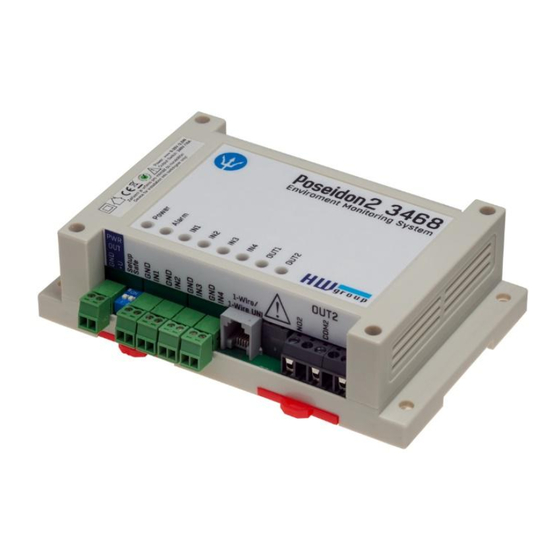
Page 4: Poseidon2 3468
Poseidon2 – Family manual HW group Poseidon2 3468 Poseidon2 4002 www.HW-group.com 4 / 104... -
Page 5: Comparison Of Specific Models
Poseidon2 – Family manual HW group Comparison of specific models Poseidon2 Poseidon2 Poseidon2 Poseidon2 3266 3268 3468 4002 Ethernet 100 Mbit 100 Mbit 100 Mbit 100 Mbit VLAN future future future future HTTP DHCP SNMP v1 SNMP v2/3 future future... -
Page 6: Connectors Description
Poseidon2 – Family manual HW group Connectors description Ethernet Ethernet 100Base-T (10/100Mbit). After connecting the adapter a green "Link" LED shows correct connection and yellow "Activity" LED flashes Power Green LED light shows that the device is powered-up. Power supply in range 9- 30V is required, for Poseidon2 3268 it is 48V. -
Page 7: Poseidon2: First Steps
Poseidon2 – Family manual HW group Poseidon2: first steps 1) Connecting the cables Turn the unit and write down its MAC address that is printed on the label on the side. Set the switches: DIP1=Off, DIP2=Off. Connect the unit to the Ethernet (with a patch cable to a switch, cross-over cable to a PC), RJ- 45 port. - Page 8 Poseidon2 – Family manual HW group Configure the network parameters IP address / HTTP port (80 by default) Network mask Gateway IP address for your network Device name (optional) Click the Apply Changes button to save the settings.
-
Page 9: Web Interface Of The Device
Poseidon2 – Family manual HW group 4) WWW interface of the device To open the WWW interface of the device: Enter the IP address into a web browser Click the IP address in UDP Config Click the underlined IP address in UDP SETUP ... - Page 10 Poseidon2 – Family manual HW group General Setup Device name, e.g. “First floor 1” Three levels of passwords for device security. SNMP 5 destinations for SNMP Traps www.HW-group.com 10 / 104...
- Page 11 Poseidon2 – Family manual HW group E-mail Inserts this text at the beginning of the e-mail subject line Up to 5 recipients for alarm e-mails E-mail test result Sends a test E-mail Periodic Status Settings Periodical Status When on, sends an e-mail with device status at the specified intervals. For example every 24 hours (1440 minutes).
- Page 12 Poseidon2 – Family manual HW group IP address of “HWg-SMS-GW” to use for sending text messages (SMS) Recipients' phone numbers Log & Time Press to synchronize the time with the specified server Expected size of recorded Interval for logging data measured values www.HW-group.com...
- Page 13 Poseidon2 – Family manual HW group Portal Message from the portal Enable connection to the remote portal Click to connect to the portal AutoPush configuration Configures the communication with the portal using the HWg-Push protocol. Poseidon2 is the active side and establishes the connection periodically and/or whenever a change in a sensor value exceeds the configured AutoPush value.
- Page 14 Poseidon2 – Family manual HW group Sensors Sends a SNMP trap if the “Safe Range” for this sensor is exceeded Range of allowed values. If exceeded, alarm is signaled. Sensor name will be shown in e-mails, text messages, or SNMP traps Sends an E-mail if the “Safe...
- Page 15 Poseidon2 – Family manual HW group Inputs Enter Digital Input name, ALARM CONTACT STATUS: Reaction to digital inputs: will be shown in e-mails, Disabled Active if On text messages or SNMP Send a SNMP Trap Alarm when the contact...
- Page 16 Poseidon2 – Family manual HW group Outputs Choose the output mode Enter Digital Input name, will be shown in e-mails, text messages or SNMP traps Pulse output timer [s]. Default Pulse Timer = 0 sets the output to a standard state.
- Page 17 Poseidon2 – Family manual HW group On if Alarm on Output = On, if the selected sensor or input is in an Alarm state. Dependent On – sensor / input to which the condition applies. System Uploads new firmware from...
-
Page 18: Connecting The Sensors
Poseidon2 – Family manual HW group Connecting the sensors 1-Wire Bus (RJ11) sensors Connect the sensor before powering up the Poseidon - the connector must click in. Max distance per active port is 60m. Sensors can be daisy-chained. -
Page 19: Rs-485 (Rj45) Sensors
Poseidon2 – Family manual HW group RS-485 (RJ45) sensors Industrial bus for connecting sensors over longer distances Connect the sensors before powering up the unit. Sensors can be daisy-chained, or connected to a virtual star using the “S-Hub” unit. -
Page 20: Common Features Of Poseidon2 Family
Poseidon2 – Family manual HW group Common features of Poseidon2 family Displayed readings options The Poseidon2 unit displays current readings from all connected sensors. Dry contact inputs are scanned approximately every 200ms. Values from all sensors on both buses (RS-485 and 1W bus) are read in a single loop that repeats once per second;... - Page 21 Poseidon2 – Family manual HW group Calibration Each sensor can be calibrated by specifying a linear offset. The calibration value can be written over XML. For calibration settings use the Calibrator utility (For download on Poseidon 2250 websites) or EX104 from HWg SDK (menu can be opened by a right-click).
- Page 22 Poseidon2 – Family manual HW group Sensor hysteresis The Hysteresis setting defines a tolerance band for alarm alerts. This feature prevents multiple alarm alerts if the reading oscillates around the specified threshold. See the graph for an explanation. Without a hysteresis of 5°C, the alarm raised at point 8 would end at point 9. With the hysteresis function, the alarm continues until the temperature rises above the tolerance band (point 10), that is, 5°C + (-15°C) = -10°C.
-
Page 23: Supported Interfaces (In Details)
Poseidon2 – Family manual HW group Supported interfaces (in details) Dry Contact Inputs Dry contacts can be connected to the clamps. For example Door contact. The inputs are electrically connected to the power supply. Unconnected inputs read as “0 (Off)”. -
Page 24: Rj11 - 1-Wire Bus
Poseidon2 – Family manual HW group RJ11 – 1-Wire bus Digital bus from company Dallas Semiconductor, each sensor has its own unique ID. We recommend to keep the total wiring length under 60m, although functionality has been achieved over tens to hundreds of meters in experimental settings. - Page 25 Poseidon2 – Family manual HW group 1-Wire (UNI) bus Supported sensors: Only new sensors supplied by HW group 1-Wire UNI: Software extension "UNI" show other than temperature or humidity sensors. Communication cable: 4-wire phone cable Polling period: 800 to 10 seconds ...
- Page 26 Poseidon2 – Family manual HW group Poseidon T-Box2 – Hub for 2 sensors Cable length: 1m Maximum number of connected sensors: 2 Connectors: RJ11 Bus type: 1-Wire bus Poseidon T-Box – Hub for 5 sensors ...
-
Page 27: Rj45 - Rs-485
Poseidon2 – Family manual HW group RJ45 - RS-485 Port 1 – RJ45 The RS-485 bus can be used to connect up to 31 sensors over up to 1000m, even in industrial environments. For convenience and ease of use, TP cables and RJ45 modular jacks are used to wire the RS485 industrial bus. - Page 28 Poseidon2 – Family manual HW group RS-485 termination on the side of Poseidon2 Poseidon2 4002 units are equipped with two DIP switches (TermA and TermB) for RS-485 bus termination. Poseidon2 4002 at the start of RS-485 line Poseidon2 4002 in the middle of RS-485 line www.HW-group.com...
- Page 29 Poseidon2 – Family manual HW group Termination of RS-485 bus The RS-485 bus must be terminated at its end. The following options are available: Internal jumper on certain sensors (jumper named TERM or TERMINATOR) – for example Temp-485 or HTemp-485 B-Cable adapter with “LAST”...
- Page 30 Poseidon2 – Family manual HW group Sensor RJ45 MIDDLE cable RS-485 cable, 0.5m, RJ45/4 pins. Connects 4 terminals (A, B, +, - ) to a RJ45 modular jack (uses 3 pairs). This cable is used to connect all sensors except for the last one in the chain.
- Page 31 Poseidon2 – Family manual HW group Poseidon Spider A converter to connect four 1Wire sensors to the Industrial bus (RS-485). Each 1Wire bus sensor connects to a separate connector to enable a greater distance (up to 1000 meters, as defined by the Industrial bus specification).
- Page 32 Poseidon2 – Family manual HW group Connection example via RS-485 °C °C °C %RH °C %RH Poseidon 1250 °C °C S-Hub Mode=MIDDLE °C °C %RH Spider Temp-485 HTemp-485 °C Temp-1Wire °C Term=ON °C °C Door Contact RJ45 Patch Straight Cable...
-
Page 33: User Interface
Device name, type, MAC address, IP address and communication port is displayed after a device is found Compatible with all HW group products (Poseidon, Damocles, PortBox, PortStore, I/O Controller, IP relay and other product lines) Windows and Linux versions available ... -
Page 34: Web Interface
Poseidon2 – Family manual HW group WEB interface Basic communication interface Poseidon offers a simple and user-friendly graphical WWW interface. Besides displaying current readings, the interface provides access to complete device configuration and management, including network settings, sensor configuration and alarm responses (SNMP traps). - Page 35 Poseidon2 – Family manual HW group Dry Contact Inputs This section displays current states of dry contact inputs, including alarm status and settings. Active alarm is indicated by a red background of the corresponding line. Name (Input name) Textual name of the input, assigned by user in the Flash Setup ...
- Page 36 Poseidon2 – Family manual HW group Line background color: White / no color = Input is not in alarm Red = Input is in alarm Yellow = Alarming is disabled for this input but the value is out of the safe range Miscellaneous information ...
- Page 37 Poseidon2 – Family manual HW group General Setup Network parameters, trusted IP address range, temperature units, output states, etc. Device Name Name assigned to a particular device. The name is shown in all lists along with the IP address (UDP Config);...
- Page 38 Poseidon2 – Family manual HW group Security Security settings. Properties of individual modes are shown in the following table. Lines indicate the method of accessing the device over IP, columns specify the restrictions resulting from the respective security settings. SNMP...
- Page 39 Poseidon2 – Family manual HW group User PasswordsTwo separate user accounts (user name and password) can be set up for SNMP and HTTP access. Account types: ‘Read Only’ can only read values and configuration settings ‘Read Only + Outputs’ can read values and set outputs, cannot change ...
- Page 40 Poseidon2 – Family manual HW group SNMP Access - communities (passwords) Two different password can be configured. Each can be set for R or R/W access and can be eventually disabled. Most SNMP applications work with the following settings (default settings). For security reasons, we highly recommend to change the R/W access password.
- Page 41 Poseidon2 – Family manual HW group Network Settings This block configures the main network parameters for Ethernet communication: IP address IP address of the unit. After a change, the device needs to be restarted Submask Local network mask. After a change, the device needs to be restarted ...
- Page 42 Poseidon2 – Family manual HW group The protection status is displayed in the bottom left-hand corner. When the HW Protection is active, any configuration changes, including changes of the output states, are ignored. This mode is useful when connecting the Poseidon to a publicly accessible network.
- Page 43 Poseidon2 – Family manual HW group SNMP Access Defines names and access rights for user groups that can work with the Poseidon unit. Community Textual name of the authorized group (usually Public and Private) Read – The community is authorized to read variables over SNMP ...
- Page 44 Poseidon2 – Family manual HW group Email & SMS Setup SMTP Server – Host name or IP address of the SMTP server SMTP Port – Port for communication with the SMTP server (25 by default) Email Sender Address – E-mail address, used as a sender of the e-mail messages ...
- Page 45 Poseidon2 – Family manual HW group Tip: It is not always necessary to configure a SMTP Server in order to send e-mails. The Poseidon can work as SMTP server itself and deliver the e-mails directly to the user’s mailbox. However, always test this mode in your particular environment – the e-mails sent in this mode are often blocked by various spam filters due to missing reverse MX records.
- Page 46 Poseidon2 – Family manual HW group GSM SMS Interface Serial Port Settings section Port Function sets the serial port function (available only for models with serial port and server part netGSM. 3 available options: Disabled – Serial port is off – Only if the modem is not connected and the device works as a client.
- Page 47 Poseidon2 – Family manual HW group GSM SMS interface Used for setting up the SMS sending parameters. GSM Function – Sets if the SMS messages will be sent through a local modem (available only when serial port is in GSM modem state) ...
- Page 48 Poseidon2 – Family manual HW group Log & Time This tab lets you configure the date, time, and logging options (if supported by the particular Poseidon model). Actual Date / Time Current date and time settings Current Date – Date in the [dd.mm.yyyy] format, for example: 31.12.2014 ...
- Page 49 Poseidon2 – Family manual HW group Time Synchronization SNTP server settings for time synchronization. If the time is not set (the date 1.1.1970 is displayed), the device attempts to synchronize the time approximately once per hour until successful. SNTP Server IP address or host name of the SNTP server to synchronize the time with.
- Page 50 Poseidon2 – Family manual HW group Portal Configures the communication with the portal using the HWg-Push protocol. Poseidon2 is the active side and establishes the connection periodically and/or whenever a change in a sensor value exceeds the configured AutoPush value.
- Page 51 Poseidon2 – Family manual HW group Server address – full URL address of a remote server IP Port – listener port of the portal Username – Username for assigning the device to a user. Will be received from the portal administrator.
- Page 52 Poseidon2 – Family manual HW group Sensors This tab configures the parameters for all sensors on both buses. Find 1Wire + RS485 sensors and Find 1Wire sensors Starts the automatic detection of connected sensors. Click the button to stop all activity and start the autodetection. The process can take a long time, even 2 minutes.
- Page 53 Poseidon2 – Family manual HW group The sensors must be with Autodetection after every change. Name – Name of the input, up to 12 chars (e.g. “above door”, “area1 humid”). Sensor ID – Unique sensor identifier, specifies its address on the bus.
- Page 54 Poseidon2 – Family manual HW group Inputs Parameters for Dry Contact inputs. Name – Name of the input, up to 12 chars (e.g. “left door”, “smoke room 1”). ID – Unique ID of the input variable within the device [1..32] ...
- Page 55 Poseidon2 – Family manual HW group Delay [s] Delays the information about alarm beginning and alarm end. Out of Safe Range Reaction to activation/deactivation of the alarm state for dry contact inputs SNMP Trap – Enables sending a SNMP trap upon alarm activation/deactivation ...
- Page 56 Poseidon2 – Family manual HW group Outputs Control and mode configuration of outputs. ID – Unique ID of the output within the device [151..215] Name – Name of the output, up to 12 chars (e.g. “top fan”, “Door rack 4”).
- Page 57 Poseidon2 – Family manual HW group Output Control Manual – Output controlled over the web or M2M protocols (XML, SNMP..) Change to On / Off – Change output state (after confirming with Apply Changes) Local Condition – Output is controlled by the sensor state condition.
- Page 58 Poseidon2 – Family manual HW group GSM modem (local or remote) Select Disabled when you want to use remote GSM modem. Select GSM Modem to use a local modem. Address of the remote GSM modem (SMS GW). Select local or remote GSM modem.
- Page 59 Uptime – Time of uninterrupted device operation (since last restart) Check for firmware updates Online check if a newer firmware version is available at the HW group server. Set Default Config – Restore factory-default settings. Restart device – resets the unit ...
-
Page 60: Update Firmware
Poseidon2 – Family manual HW group Update Firmware Updating the firmware over the WEB http://x.x.x.x/upload/. Upload the firmware in a .hwg file over HTTP to Connection cannot be interrupted during the transmission. If the FW is not loaded correctly this way, use the previously mentioned RS-232 update option to upload the file. -
Page 61: Software Applications
Poseidon2 – Family manual HW group Software Applications HWg-PDMS Windows application that logs data from all HW group devices into its internal database. The application runs in the background (NTservice). Data are retrieved from the device over HTTP or e-mail. - Page 62 Poseidon2 – Family manual HW group PosDamIO Poseidon Damocles I/O is a command-line utility for Windows and Linux that lets you control Poseidon and Damocles units over the XML interface. Calling the program can print out the sensors, inputs and outputs states, but also set an output to a log.
-
Page 63: Connecting Poseidon2 To Sensdesk Portal
Poseidon2 – Family manual HW group www.SensDesk.com Connecting Poseidon2 to SensDesk portal Connecting to the portal 1) Connect the device to a computer network and set the network parameters (More in First steps chapter in the user manual). 2) Go to the device's WWW setup, Portal tab, in the Portal Config section tick the Portal field, save the changes and then press the Manual Push button. - Page 64 Poseidon2 – Family manual HW group www.HW-group.com 64 / 104...
- Page 65 Poseidon2 – Family manual HW group 3) By clicking the SensDesk.com: register your IP sensor link you will be redirected to the SensDesk.com service website - to a login dialog. 4) If you already have a user account, enter the login details and the device will be automatically assigned to your account.
- Page 66 Poseidon2 – Family manual HW group 6) Account activation will redirect you to an Invitation page. Test the portal reaction to your devices. After leaving the page the reaction time to changes in measured values will increase to 15 minutes. In case a shorter time is needed, set the "AutoPush"...
-
Page 67: Using Poseidon2 Units In Your Applications
Poseidon2 – Family manual HW group Using Poseidon2 units in your applications PosDamIO – Command line control Poseidon Damocles I/O is a command-line utility for Windows and Linux that lets you control Poseidon and Damocles units over the XML interface. Calling the program can print out the sensors, inputs and outputs states, but also set an output to a log. -
Page 68: Hwg-Sdk
HWg SDK is simple to understand HWg SDK speeds up the implementation of HW group products in your SW With HWg SDK, you don’t have to worry about future changes of structures, interface updates, and so on ... - Page 69 I/O pins of the I/O Controller device. Written in Borland C++ Builder using the HWg SDK. I/O pins are controlled with NVT commands based on a RFC2217 extension by HW group. Functions used: hwudps_init, hwudps_uninit, hwudps_reinit, hwudps_search, hwudps_search_finish, hwudps_count,...
- Page 70 Poseidon2 – Family manual HW group EX104: XML file downloader XML A An example to demonstrate UDP search for devices, reading their basic network parameters, and downloading and parsing the XML file with sensor and binary input states. Values can be downloaded from one device only at a time.
- Page 71 Poseidon2 – Family manual HW group Demonstrated features Receiving traps from multiple devices at a time Support for Poseidon and Damocles family Parsing known traps and writing them to the log Downloading detailed information about all sensors from a specified device ...
- Page 72 Poseidon2 – Family manual HW group Storing all values from all devices into one large shared table Setting the digital outputs Setting the safe range thresholds for analog sensors EX111: Simple Setting of Outputs A very simple application shows how to change the values of digital outputs.
- Page 73 Poseidon2 – Family manual HW group EX115: Poseidon & Damocles I/O The PosDamIO utility is designed for batch scripts and applications that need to easily control or log remote sensors, digital inputs and outputs. It is written in C and compiled in Borland C++ Builder using the HWg SDK.
- Page 74 HW group Documentation for programmers Generated automatically using the Doxygen system Opens after SDK installation or by clicking HW group SDK > HWg SDK main page Conclusion: Register and download the current SDK version on the page: http://www.hw-group.com/ www.HW-group.com...
-
Page 75: Poseidon Formats And Interfaces
Poseidon2 – Family manual HW group Poseidon formats and interfaces SMS – Interface description SMS format DEVICE_NAME #ALARM SENSOR1_NAME:VALUE/EXCEEDED_THRESHOLD SENSOR1_NAME:VALUE/EXCEEDED_THRESHOLD #STATUS: INP: 0 0 0 SENS:VALUES_OF_ALL_SENSORS_CONNECTED_TO_UNIT Description: Values are separated with spaces DEVICE_NAME is truncated to a maximum of 8 characters ... -
Page 76: E-Mail - Interface Description
Poseidon2 – Family manual HW group E-mail – Interface description <---------------------------61-----------------------------> <---10---> <---8--> <------16------> <------15-----> <-5-> <------15-----> <---11 ---> <------16------> <--8---> DATE TIME Device_NAME Device_IP XX.XX.XXXX XX:XX:XX XXXXXXXXXXXXXXXX XXX.XXX.XXX.XXX Email initiated: XXXXX XXXXXXXXXXXXXXX XXXXXXXXXXXXXXX ------------------------------------------------------------ SENSOR_Name VALUE UNIT Safe_RANGE ALARM... - Page 77 Poseidon2 – Family manual HW group E-mail subject: The following strings are appended to the specified e-mail subject: “Test” for the test e-mail “Periodical report” for the periodically e-mailed report “T-Room Alarm ACTIVATED” when the alarm for the sensor named T-Room is activated ...
- Page 78 Poseidon2 – Family manual HW group Alarm deactivation: DATE TIME Device_NAME Device_IP 10.10.2005 15:04:27 Server_room1 192.168.1.20 Email initiated: 48245 T-Room Alarm DEACTIVATED ------------------------------------------------------------ SENSOR_Name VALUE UNIT Safe_RANGE ALARM ------------------------------------------------------------ ALARM state: ------------------------------------------------------- 1 C-water if OFF Sensors list: -------------------------------------------------- 48245 T-Room 21.30...
-
Page 79: Xml - Interface Description
Poseidon2 – Family manual HW group XML – Interface description Poseidon supports the following XML files: values.xml Small file for periodical polling of sensor readings. Subset of setup.xml – only basic identification and sensor readings are included. setup.xml... - Page 80 Poseidon2 – Family manual HW group Setup.xml format – version 2.37 Release notes for the actual version can be always found at http://new.hwg.cz/cs/node/4561 Information Section <Agent> - Read only device parameters group - Device firmware version (Read only) <Version>1.1.12</Version> - XML file version (Read only) <XmlVer>2.37</XmlVer>...
- Page 81 Poseidon2 – Family manual HW group Input, Output and Sensor Section - Binary dry contact inputs (next only “Binary input”) <BinaryInSet> <Entry> - Entry identification, CondInputID> for output control, ID in <ID>1</ID> ID (1..64), source for < unique per device, 1..64 are reserved for binary inputs - Defined name of the input (text string, 20 chars) <Name>Binary 1</Name>...
- Page 82 Poseidon2 – Family manual HW group <Entry> - Entry identification <ID>152</ID> <Name>DTR</Name> <Type>2</Type> <Value>0</Value> <Mode>3</Mode> <CondInputID>75</CondInputID> <Trigger>22.5</Trigger > </Entry> </BinaryOutSet> - All detected sensors <SenSet> <Entry> - Entry identification, ID address of the sensor (Read only) <ID>57856</ID> , source for CondInputID>, ID in unique per device,...
- Page 83 Poseidon2 – Family manual HW group RS-232/GSM Settings <SerialPort> <E>1</E> - Enable Serial Port 0= Disabled, 1=GSM modem, 2=RFID reader </SerialPort> <SMS> <Function>0</Function> - Function 0-Local Modem, 1=Remote GSM GW <Ring>0</Ring> - Enable Ring alert (0/1) <Dest>1</Dest> - Remote SOAP GW destination number <Module>Not enabled</Module>...
- Page 84 Poseidon2 – Family manual HW group - Value of the IP subnet mask (Read only when DHCP enabled) <Submask>255.255.255.0</Submask> - IP address of the Gateway (Read only when DHCP enabled) <Gateway>192.168.1.100</Gateway> - Primary DNS server (you have to set DNS server as IP address) (Read only when DHCP enabled) <DNSPrimary>147.230.16.1</DNSPrimary>...
- Page 85 Poseidon2 – Family manual HW group <Entry> <Idx>1</Idx> - Alert email - Recipient of Email (40 chars) <To>recip@domain.com</To> - Recipient of Email (40 chars) <Cc>recip@domain.com</Cc> - Recipient of Email (40 chars) <Cc1>recip@domain.com</Cc1> - Recipient of Email (40 chars) <Cc2>recip@domain.com</Cc2> - Recipient of Email (40 chars) <Cc3>recip@domain.com</Cc3>...
- Page 86 Poseidon2 – Family manual HW group - Name (32 chars) <Name></Name> - Password (filled by “*”)(32 chars) <Pswd></Pswd> </Entry> Read &Write Outputs, Read only device configuration <Entry> <Idx>2</Idx> - Name <Name></Name> Password (you can see current Password in Flash Setup) <Pswd></Pswd>...
-
Page 87: Logger Format
Poseidon2 – Family manual HW group Logger format Logged data from the logger: x.x.x.x/spilog.bin binary format of the logged data x.x.x.x/spilog.txt Text format (CSV) of the logged data x.x.x.x/spilog.del call this file to delete logged data and start logging again Logger is circuit buffer = oldest data are rewrite by newer data. - Page 88 Poseidon2 – Family manual HW group File spilog.bin u_char occupied_bytes; // record length (total include length) u_char type; // log_type - type of record time_t time; // time of sampling (u_long) u_char type; // log_group - sensor type u_char count;...
-
Page 89: Modbus Over Tcp - Interface Description
Poseidon2 – Family manual HW group Modbus over TCP – Interface description Modbus is a communication protocol designed for measuring devices that communicate over RS-485 or RS-232 (sometimes named Modbus RTU). The Modbus protocol itself allows to share the memory area for variables, e.g. the readings, over one of the physical interfaces. Modbus/TCP is an extension of this protocol for communication over Ethernet. - Page 90 Poseidon2 – Family manual HW group Testing Modbus/TCP with “Modbus Poll 3.20” The supplied CD contains the Modbus Poll utility, which can serve as a simple client for reading Modbus/TCP values – for 30 days after it is run for the first time.
-
Page 91: Hwg-Netgsm - Remote Sms Gateway Protocol For Hw Group Products
GSM modem, connected to one unit, with other devices in the same network. This allows several HW group devices to send alarm SMS messages via one device (one SIM card). This solution decreases the operating costs. - Page 92 Poseidon2 – Family manual HW group Settings example for two Poseidon units re-sending SMS messages through the second unit Two Poseidon units are used for the settings: 192.168.2.23 Poseidon 4002 with connected GSM modem 192.168.1.67 Poseidon 3266 sending SMS messages via Poseidon 4002...
- Page 93 Poseidon2 – Family manual HW group Poseidon 3266 (Transmitting device) settings In default settings it is vital to keep the correct remote Poseidon IP address settings and settings of phone numbers for sending SMS messages. SMS+ Ring when Alarm function is optional.
-
Page 94: Communication Examples
Poseidon2 – Family manual HW group netGSM protocol for programmers Poseidon SOAP Service Interface (PSSI) Configure hostname/port on HWg-SMS-GW where the service request will be sent. Services (common API, SOAP interface) Service Functions Parameters Result XML with data, cmd=SMS, rslt=0, id=nnn: ID of the... - Page 95 Poseidon2 – Family manual HW group Put SMS into the queue <pos:QueueAdd> <Queue>GsmOut</Queue> <Gsm> <Cmd>SMS</Cmd> <Nmr>00420800123456</Nmr> <Text>Poseidon: halo halo</Text> </Gsm> </pos:QueueAdd> Reply: <pos:QueueAdd> <Rslt>0</Rslt> <ID>120</ID> </pos:QueueAdd> Put drop-call into the queue <pos:QueueAdd> <Queue>GsmOut</Queue> <Gsm> <Cmd>Call</Cmd> <Nmr>00420800123456</Nmr> <Gsm> </pos:QueueAdd> Reply: <pos:QueueAdd>...
- Page 96 Poseidon2 – Family manual HW group Reply: <pos:QueueStatus> <Rslt>0</Rslt> <Max>5</Max> <Cnt>2</Cnt> <Missed>0</Missed> <IdSet> <ID>120</ID> <ID>121</ID> <ID>122</ID> <ID>123</ID> <IdSet> </pos:QueueStatus> Get queue record status <pos:RecordStatus> <Queue>GsmOut</Queue> <ID>120</ID> </pos:RecordStatus> Reply: <pos:RecordStatus> <Rslt>0</Rslt> <Retry>5</Retry> </pos:RecordStatus> Erase queue record <pos:RecordDelete> <Queue>Rfid</Queue> <ID>120</ID> </pos:RecordDelete> Reply: <pos:RecordDelete>...
-
Page 97: Snmp - Interface Description
Poseidon2 – Family manual HW group SNMP – Interface description SNMP (Simple Network Management Protocol) is a protocol designed for exchanging basic system information using short packets sent over UDP/IP. Individual variables are described in a MIB (Management Information Base) table that pertains to a particular device. - Page 98 Poseidon2 – Family manual HW group Downloading the MIB file from the main product web page The MIB file is located in the device itself. Use the right mouse button in your browser to download and save it. www.HW-group.com 98 / 104...
- Page 99 Poseidon2 – Family manual HW group OID descriptions of SNMP variables The following table lists the variables, their OID addresses and values. The values apply to the specified Poseidon configuration shown in the HTML page screen shot on the right.
- Page 100 Poseidon2 – Family manual HW group Shortened OID list Poseidon family SNMP OID description ---------------------------------------------------------------------------------------- Poseidon Device Values: ------------------------------------------------------- .1.3.6.1.2.1.1.1.0 Device description (string) .1.3.6.1.2.1.1.5.0 Device name (string) Dry Contact Inputs ------------------------------------------------------- .1.3.6.1.4.1.21796.3.3.1.1.2.1 Contact Input 1 state (integer, 1=Off, 2=On) .1.3.6.1.4.1.21796.3.3.1.1.2.3 Contact Input 3 state (integer, 1=Off, 2=On) .1.3.6.1.4.1.21796.3.3.1.1.3.1...
-
Page 101: Snmp Trap - Interface Description
Poseidon2 – Family manual HW group SNMP Trap – Interface description Whenever a value gets outside of the safe range for a sensor, the sensor enters the ALARM state. To notify about the alarm state, a SNMP trap is send to the specified IP address. - Page 102 Poseidon2 – Family manual HW group Recommended SW for SNMP experiments GetIf GetIf is a utility for working with SNMP variables. It allows browsing the variables in the SNMP tree, reading the values, setting the values, and displaying details according to the MIB.
- Page 103 Poseidon2 – Family manual HW group iReasoning MIB Browser + Trap Receiver Two freeware utilities for working with SNMP variables. They allow browsing the variables in the SNMP tree, reading the values, setting the values, and displaying details according to the MIB that can be loaded to the utility.
-
Page 104: Connectors And Connections
Poseidon2 – Family manual HW group Connectors and connections DB9M: RS-232 Power connector Not used <-- Receive Data 2 RxD --> Transmit Data 3 TxD --> Data Terminal Ready 4 DTR 5 GND --- System Ground 6 DSR <-- Data Set Ready -->...
Need help?
Do you have a question about the Poseidon2 3266 and is the answer not in the manual?
Questions and answers