Table of Contents
Advertisement
Quick Links
SERVICE MANUAL
COMPRESSOR WINCH
• REPAIR / REPLACEMENT INSTRUCTIONS
• TROUBLE SHOOTING GUIDE
As you read these instructions, you will see NOTICES, CAUTIONS and
WARNINGS. Each message has a specific purpose. A NOTICE is additional
information to help you complete a procedure. CAUTIONS are safety messages
that indicate a potentially hazardous situation which, if not avoided, may result in
minor or moderate injury. A CAUTION may also be used to alert against unsafe
practice. WARNINGS are safety messages that indicate a potentially hazardous
situation, which, if not avoided could result in serious injury. CAUTIONS and
WARNINGS identify the hazard, indicate how to avoid the hazard, and advise of
the probable consequence of not avoiding the hazard. PLEASE WORK SAFELY!
1
FOR THE
WARN
POWERPLANT
HP & HD
12V DC
Warn Industries, Inc
12900 SE Capps Road
Clackamas, OR 97015 USA
REV A
Advertisement
Table of Contents

Subscribe to Our Youtube Channel
Related Manuals for Warn POWERPLANT HP


Summary of Contents for Warn POWERPLANT HP
- Page 1 CAUTIONS and WARNINGS identify the hazard, indicate how to avoid the hazard, and advise of the probable consequence of not avoiding the hazard. PLEASE WORK SAFELY! Warn Industries, Inc 12900 SE Capps Road Clackamas, OR 97015 USA...
-
Page 2: Table Of Contents
TABLE OF CONTENTS SECTION 1 - GETTING STARTED -------------------------------3 1.1 WINCH MODEL IDENTIFICATION------------------------------------------------------- 3 1.2 DEFINITIONS AND WINCH OPERATION ---------------------------------------------- 4 SECTION 2 – DISASSEMBLY & ASSEMBLY ---------------- 10 2.1 SERVICE TECHNICIAN REPAIRS ------------------------------------------------------ 10 2.2 SUGGESTED TOOLS ----------------------------------------------------------------------- 10 2.3 DISASSEMBLY ------------------------------------------------------------------------------ 11 2.4 REASSEMBLY ------------------------------------------------------------------------------- 16 SECTION 3 –... - Page 3 SECTION 6 – WINCH TROUBLE SHOOTING--------------- 54...
-
Page 4: Section 1 - Getting Started
SECTION 1 - Getting Started 1.1 Winch Model Identification To ensure proper winch repair it is necessary to correctly identify the model and part number of your winch. This makes ordering replacement parts easier, and helps you obtain the necessary For a part description, item information from your Authorized Service Center. -
Page 5: Definitions And Winch Operation
Definitions and Winch Operation 1.2.1 Definitions Operation and service of a Warn planetary winch can be explained easier by defining a few major structural components. Refer to the following figures for definitions. MOTOR: The winch and the compressor pump are driven by a high speed, low torque electric motor. - Page 6 Cylinder Head Compressor Inlet Piston Cylinder Pressure Switch Contactor Motor Pressure Relief Valve Free Spool Clutch Figure 1.3 Winch Components MOTOR CONTROLS: The electric winch motor controls consist of a Contactor control , which pack is mounted to the motor, and a remote control handle connected to the control pack with a cord.
-
Page 7: Powerplant Operation
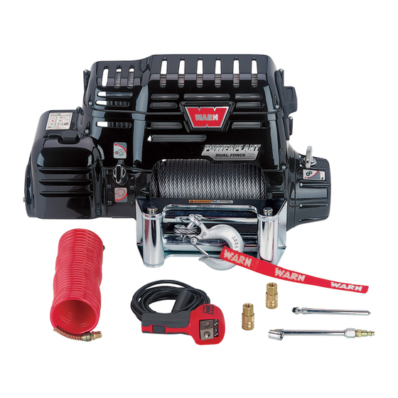
1.2.2 PowerPlant Operation The Warn PowerPlant is a compact device used to pull heavy loads over short distances up to 100’, or as a Compressor to inflate tires and operate most air tools. The vehicle battery and charging system generates the power for pulling the load or operating the Compressor. -
Page 8: Remote Control
Remote Control Do not leave the remote control plugged into the PowerPlant when not in use. Leaving the remote plugged in may result in a dangerous condition and / or battery drain. Winch Control Switch The large rocker switch on the Remote Control handle controls the spooling in and spooling out function of the winch. - Page 9 To prevent any damage to the winch motor due to high heat, there is a thermal protection device in the motor. This device will shut off the motor and cause the indicator light in the remote control to blink when the factory set high temperature point is reached and either switch is depressed.
-
Page 10: Clutch Operation
CLUTCH OPERATION The clutch knob, located on the housing opposite the motor, controls the clutch position. When the clutch is engaged the gear train is coupled to the wire rope drum and power may be transferred from the winch motor. When the clutch is in free spool the gear train and wire rope are uncoupled and allows the drum to rotate freely. -
Page 11: Suggested Tools
READ THIS BEFORE BEGINING REPAIRS IT IS IMPORTANT THAT YOU MAKE REPAIRS WITH THE PROPER TOOLS AND EQUIPMENT. IT IS ALSO IMPORTANT TO CORRECTLY FOLLOW THE INSTRUCTIONS. FAILURE TO DO SO MAY CAUSE THE WINCH TO FAIL RESULTING IN SERIOUS BODILY INJURY OR PROPERTY DAMAGE. - Page 12 ALWAYS DISCONNECT ALL WIRES FROM THE POSITIVE BATTERY TERMINAL BEFORE BEGINNING ANY WORK ON THE WINCH. FAILURE TO DO SO MAY BE A FIRE HAZARD AND RESULT IN SERIOUS BODILY INJURY OR PROPERTY DAMAGE. Remove rubber Air Access Door. Slide it off the locating tab Remove 4 Top Cover cap screws, lift off top cover.
- Page 13 Remove two wires from Pressure Switch, note the routing of these wire for reassembly. Remove Air Inlet hose from fitting if not previously removed. Remove 3 ¼ x 20 x 10 inch allen head cap screws. These pass through the intercooler and thread into the motor side drum support.
- Page 14 Remove Intercooler from drum support by removing one allen had cap screw, shown. Slide drum away from Drum Support. Drive shaft and drive gear will slide out also. The 3 stage ring gear may stay attached to end housing. Sun gear, 1 stage, 2 stage and 3 stage...
- Page 15 Ring gear can now be removed, a rubber mallet may be needed to break it free. Inspect ring gear gasket for damage. Remove free spooling clutch lever from the gear housing by removing the allen head set screw then lifting the handle out of the housing.
-
Page 16: Reassembly
NOTES: Reassembly... - Page 17 Apply machine oil to machined portion of end housing. NOTE: Do not apply grease to the machined surface of the gear housing. This will cause difficulty in free spooling. Install sliding ring gear with the beveled teeth down. Grease teeth of sliding ring gear with moly lube.
- Page 18 Clean gasket surface of end housing and install gasket to end housing. Using two allen head screws for alignment, slide ring gear onto drum support. NOTE: Ensure Ring Gear is fully seated into teeth on drum support. Fill Ring Gear teeth with moly lube. Install the 3 stage gear.
- Page 19 Fill teeth of 2 stage gears and 1 stage sun gear with moly lube and slide into place. Apply light machine oil to sun gear before sliding into 1 stage planetary gear. Clean gasket surface and install ring gear gasket as shown. NOTE: The Clutch Lever must be in Free Spool Position before installing gear housing.
- Page 20 Apply a light coating of grease to the inside of the drum bushing and install it on the gear housing. NOTE: For the bushing to fit properly the slot in the bushing must fit over the index tab in the drum support. Install the drive spline into the 3 stage gear carrier.
- Page 21 Make sure the drum is seated all the way into the drum support bushing and the drum is seated into the Drive Spline. Install Intercooler with one allen head cap screw. Align the Two Assemblies. Hint – Placing a ½ inch shim spacer under the drum and motor will help with the alignment of both ends.
- Page 22 Install 3 ¼ x 20 x 10 inch allen head cap screws. These pass through the intercooler and thread into the motor side drum support. Install two wires to Pressure Switch terminals. NOTE: Wires must be routed under the bracket. Tighten 5/8 inch air line fitting.
- Page 23 Install 4 Mode Cover allen head screws. Install top cover and secure with 4 allen head screws. Install QD Plug Air Access Door. NOTES:...
-
Page 24: Suggested Tools
SECTION 3 Brake Removal And Replacement Warn Industries does not offer individual replacement brake parts. The complete brake assembly must be replaced. Suggested Tools 7/32" These tools are suggested for the following procedures: Hex Key Wrench, Rubber Mallet. Disassembly Follow Winch Disassembly procedures in section 2.3 and separate winch. - Page 25 The brake unit is spring loaded. Should the brake unit unwind it will be necessary to replace it with a new brake assembly. Never attempt to rewind a brake unit that has come unwound. It will cause loss of brake function. This could lead to serious personal injury or death.
- Page 26 3.3 Reassembly/ New Brake Installation Set the drum assembly on a solid work surface and slide the brake unit through the cardboard sleeve into the drum about 3”. Brake assembly installed into drum. Always position the motor coupler tangs properly. Failure to do so, will cause brake This could lead to serious personal failure.
- Page 27 Install the aluminum motor coupler. Install the wear washer, apply a thin layer of grease to both sides of the washer. Apply grease to the outer edge of the coupler splines. To ease installation position a clutch ring spline in the 12:00 o’clock position Position a motor coupler spline in the 12:00 o’clock position, then slide to two assemblies together.
-
Page 28: Reassembly
Reinstall drum to gear side drum support and follow instructions in section 2.4 to reassembly. NOTES:... -
Page 29: Overview And Wiring
SECTION 4.0 - Electric Motor & Control Pack Overview and Wiring Reference MOTOR TERMINALS F-2 Terminal F-1 Terminal A Terminal Figure 4.1... - Page 30 4.1 Overview of Contactor Operation Electrical operation of the PowerPlant control assembly consists of a heavy duty contactor. When the winch operating switch is being operated it directs the contactor to either power-in or power-out the winch when in Winch Mode. The compressor control switch directs the contactor to operate the compressor when in Compressor Mode.
- Page 31 4.2 Contactor, Electric Motor and Motor Brush Removal ALWAYS DISCONNECT ALL WIRES FROM THE POSITIVE BATTERY TERMINAL BEFORE BEGINNING ANY WORK ON THE WINCH. FAILURE TO DO SO MAY CAUSE THE WINCH TO FAIL RESULTING IN SERIOUS BODILY INJURY OR PROPERTY DAMAGE. Disassemble PowerPlant following the instructions in Section 2.3 and separate the gear end housing with drum and intercooler...
- Page 32 Remove tie wraps, then disconnect 2 prong TPD plug. Disconnect 4 prong contactor harness connector. Remove motor ground bolt, negative battery cable and white ground wires. To remove contactor from motor, remove 4 nuts. 2 from the A terminal bus bar and 1 each from the F-1 and F-2 terminals.
- Page 33 4.3 CONTACTOR AND ELECTRIC MOTOR REPLACEMENT Mode Selector Must Be In Winch Mode before Removing Motor to Ease Reinstallation Place motor gasket onto the Crankcase assembly Install the motor, note the motor locating pin and the cooresponding hole in the crank case housing.
- Page 34 Install the “A” terminal bus bar. Tighten 4 nuts. Attach the negative battery cable and white wires to motor ground bolt. Route all wires carefully, use this diagram for correct wire locations. Use tie wraps to sucure loose wires.
-
Page 35: Motor Brush Replacement
4.4 MOTOR BRUSH REPLACEMENT Remove motor end cap from motor housing. Plastic brush holder and brushes will be visible. Note the location of the armature bearing in the brush holder. 4 plastic lock tabs secure the bearing. Remove screw from copper strap. This will allow the release of the brush holder from the motor housing. - Page 36 Remove the brush holder from the motor housing. Inspect brushes, replace brushes if they measure less then 1/2 inch in length. Note the location of the slot the brass strap slides through. Secure the four brushes. Pull the brush outward and angle them up so they stay secured in the bracket.
- Page 37 Secure motor housing strap to brush holder. Secure brush holder to motor housing with Phillips screw. Inspect all electrical connections to ensure they are tight. Inspect cable insulation for damage, and make sure cables are not being pinched. Reinstall motor cap assembly. NOTES:...
- Page 38 4.5 ELECTRICAL CIRCUIT TESTING Remote control plug located on Contactor pin reference numbers. 4.5.1 Contactor Function Test Equipment: 5 A power supply set to 12v Ohm meter Jumper wire with alligator leads PowerPlant remote control Connect 4-pin trailer plug to power supply as shone in the first diagram.
- Page 39 Test Operate the remote by pressing power-in switch and power-out switch. Operate the remote several times to check for intermittent contactor function. Test Results If meter reads ~0 Ohms for power-in and power-out, the contact or is good If meter reads higher than ~0 Ohms the contactor has high resistance and needs further evaluation on the milivolt drop test.
- Page 40 Test Disconnect the 2 pin plug from the winch motor and the wire harness. Measure resistance across the two terminals of the plug. Test Results If the meter reads ~0 Ohms the TPD is good. If the meter reads more the ~0 Ohms the TPD is bad or the connector is bad.
- Page 41 4.5.6 Pressure Switch Test Disconnect the wires that are attached to the pressure switch. Measure resistance across the switch terminals. Test Results If the meter reads ~0 Ohms then the switch is good. If the meter reads higher then ~0 Ohms then the switch needs to be replaced or the connections are bad.
-
Page 42: Compressor Components
5.1 Compressor Components Cylinder Head Valve Plate Cylinder Piston Crank Shaft Assembly Drum Support Figure 5.1 Crank Case Assemble Components... - Page 43 Crank Case Housing Mode Selector Switch Piston Thrust Washer Crank Assy Motor Pulley Assy Switch Fork Spring Clutch Ring Figure 5.2...
- Page 44 Crank Case Assemble Components Piston Mode Selector Switch Crank Assy Belt Switch Fork Micro Switch Figure 5.3 5.2 COMPRESSOR DISSASEMBLY...
- Page 45 Follow Winch Disassembly procedures in section 2.3 and separate winch. Hint – Placing a ½ inch shim spacer under the drum and motor will help prevent binding. Remove Contactor. See instructions in section 4.2 Motor removal Remove motor. Remove 4 cylinder head bolts.
- Page 46 Remove cylinder head. Remove Valve Plate assembly. Note poistion of Roll Pin. Remove cylinder and gasket. Note position of two dowel pins. Remove 5 allen head screwes that attach the drum support to the compressor housing.
- Page 47 Seperate drum support from Crank Case assembly and housing. Crank case assembly. Micro Switch harness assembly removal. Carfully remove crank case gasket. Pull rubber grommet with wires from housing. Remove allen head screw. Note postion of Micro switch lever above switch fork tab.
- Page 48 Remove spring from shaft, (already removed in this photo).. Remove shift fork and clutch ring. Remove crank assembly, motor pulley and belt as one assembly. Place Mode Selction switch in Winch Mode. Remove allen head screw and slide mode selctor switch away from housing. NOTES...
- Page 49 5.3 REASSEMBLY Apply grease to Mode Selector Switch quad seal. Place Mode Selction switch in Winch Mode position. Slide the Selector switch into the housing and secure with the allen head set scerw. Install motor gasket to motor. Install winch motor into housing, note the position of the motor locating pin and align it with the hole in the housing.
- Page 50 Alighn the crankshaft counter weight in the 12:00 oclock position with piston as shown. Partially slide motor pulley on motor armature shaft. Slightly angle crank assembly as shown. Slide pin into bearing on crank case. Slide the crank assembly into place by placing both hands on the counter weight.
- Page 51 Center crank assembly in housing as shown and rotate piston into the 12:00 oclock position. Apply a small amount of moly lube to shift fork pin. Slide shift fork onto the pin and align with the motor pulley. Slide spring onto pin.
- Page 52 Install the micro switch. NOTE: Micro Switch Lever MUST rest on top of the Shift Fork Tab to function properly. Ensure micro switch mount plate seats correctly into machined area of crank case. Slide the rubber grommet with wire harness into slot.
- Page 53 Inspect cylinder wall for excessive wear. Install new cylinder gasket, align with two dowel pins. Rotate cylinder to about 45 degrees, then slide over piston. Slide cylinder down piston and align with two dowel pins. Install new valve plate gasket to top of cylinder.
- Page 54 Install cylinder head, line up roll pin with hole in cylinder head. Install 4 allen head screws. Tighten in a criss-cross pattern. Align Gear End Housing with Intercooler and drum with the Motor drum support. Hint – Placing a ½ inch shim spacer under the drum and motor to help with the alignment of both ends.
- Page 55 SECTION 6 Winch Trouble Shooting Guide – WINCH MODE PROBLEM POSSIBLE CAUSE CORRECTIVE ACTION Winch does not run Battery Discharged Check charge level and condition of battery Loose or corroded battery Clean and tighten battery cable connections. connections Mode Selector in Compressor Place Mode Selector in Winch Mode Mode...
-
Page 56: Compressor Mode
PROBLEM POSSIBLE CAUSE CORRECTIVE ACTION Air tank is pressurized tripping Remove air hose from air tank to pressure switch relieve air pressure from compressor. Air Tank is Pressurized tripping Remove air hose from the air the pressure switch tank to relieve air pressure from the compressor. - Page 57 “power out” function will still tripped operate in case it is necessary to release a load Quick connect fittings will not Warn uses “industrial Change over to “industrial accept customers non-Warn interchange” fittings interchange” fittings. accessories...
Need help?
Do you have a question about the POWERPLANT HP and is the answer not in the manual?
Questions and answers