Advertisement
Your safety, and the safety of others, is very important. To help you make informed decisions about safety, we have provided installation
and operating instructions and other information on labels and in this guide. This information alerts you to potential hazards that could
hurt you or others. It is not possible to warn you about all potential hazards associated with this product, you must use your own good
judgment.
CARELESS INSTALLATION AND OPERATION CAN RESULT IN SERIOUS INJURY OR
EQUIPMENT DAMAGE. READ AND UNDERSTAND ALL SAFETY PRECAUTIONS AND
OPERATING INSTRUCTIONS BEFORE INSTALLING AND OPERATING THIS PRODUCT.
This guide identifies potential hazards and has important safety messages that help you and others avoid personal injury or death.
WARNING and CAUTION are signal words that identify the level of hazard. These signal words mean:
WARNING signals a hazard that could cause serious injury or death, if you do not follow recommendations.
CAUTION signals a hazard that may cause minor to moderate injury, if you do not follow recommendations.
This guide uses NOTICE to call attention to important mechanical information, and Note: to emphasize general information worthy of
special attention.
SEVERE INJURY OR DEATH MAY RESULT IF YOU IGNORE ANY OF THE
FOLLOWING.
• Read the Winch Operator's Manual, ATV Operator's Manual, and all warning labels before
operating the winch and ATV.
• Stay clear of moving parts and cable. Keep others away when operating the winch.
• Inspect the winch mechanism, fasteners, and cable, before operating. Replace all worn or damaged
parts before operating.
• Make sure the winch is deactivated when leaving the ATV unattended.
PART NO.
61223
61302
61281
780427
2079
1402
21331
22510
3693
61485
61486
22491
780428
22508
WARN INDUSTRIES
INSTALLATION INSTRUCTIONS
ATV WINCH MULTI-MOUNT
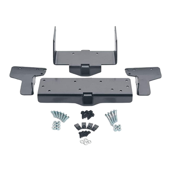
Multi-Mount Mounting-Kit: PN 61020
Application: KAWASAKI, PRAIRIE 400
WARNING
PARTS LIST:
QUANTITY
1
1
1
4
20
20
8
2
3
1
1
2
2
2
TOOLS NEEDED:
7/16" , 1/2" Socket & Wrench
10mm, 12mm, 13mm, 17mm Socket & Wrench
Phillps-Head Screw-driver
DESCRIPTION
REAR RECEIVER BRACKET
RIGHT-REAR SIDE BRKT
LEFT-REAR SIDE BRKT
5/16-18 x 1" U-BOLT
5/16-18 HEX NUT
5/16 LOCKWASHER
5/16-18 x 1" HEX BOLT
M8 X 1.25 X 50mm HEX BOLT
FRONT RECEIVER BRACKET
LOWER SUPPORT BRKT
M8 NYLOCK NUT
5/16-18 x 1.125" U-BOLT
M8 x 1.25 x 25mm HEX BOLT
PAGE 1
¼" SPACERS
61285 Rev C0
Advertisement
Table of Contents

Subscribe to Our Youtube Channel
Related Manuals for Warn PN 61020


Summary of Contents for Warn PN 61020
- Page 1 This information alerts you to potential hazards that could hurt you or others. It is not possible to warn you about all potential hazards associated with this product, you must use your own good judgment.
- Page 2 Then while holding it in place in that location, tighten the 5/16”nuts to an approximate torque of 21 ft-lbs. Then, tighten the remaining 5/16” nuts to an approximate torque of 21 ft-lbs. WARN INDUSTRIES PAGE 2 61285 Rev C0...
- Page 3 U-bolts that have been installed in the previous step. Torque the M8 bolts to an approx. 21 ft-lbs. LONGER M8 BOLTS SPACER NEEDED TWO SPACERS HERE NEEDED HERE (MUFFLER) FIGURE 3 WARN INDUSTRIES PAGE 3 61285 Rev C0...
- Page 4 Remove the three screws on each side of the bike as shown in the Figure 5 below, inorder to patially remove the plastic side walls. This will help better facilatate installation. FIGURE 5 WARN INDUSTRIES PAGE 4 61285 Rev C0...
- Page 5 5/16”-18 x 1” bolts and two U-bolts, lock washer and nuts. Tighten all the 5/16” and M8 nuts to an approximate torque of 21 ft- lbs. FIGURE 7 WARN INDUSTRIES PAGE 5 61285 Rev C0...
- Page 6 . Replace the six screws to secure the plastic side walls back into place. WINCH-CARRIER PLATE INSTALLATION: 1. Attach the WARN winch and the associated fairlead to the WINCH-CARRIER PLATE, using the fasteners that were included with the winch. Make sure that the 5/16-18 bolts that attach the winch to the WINCH-CARRIER PLATE are torque to an approximately 20 ft-lbs.
- Page 7 Refer to the WINCH OPERATOR’S MANUAL for full and complete details on wiring installation. CAUTION: The hook ( or toe-strap, etc.) should NEVER be hooked into either of the handles of the winch-carrier- plate. This will cause permanent damage to the winch-carrier-plate. WARN INDUSTRIES PAGE 7 61285 Rev C0...
Need help?
Do you have a question about the PN 61020 and is the answer not in the manual?
Questions and answers