Warn ZEON 8 /10 / 12, ZEON Platinum 10 / 12 Manual
- Installation and operator's manual (38 pages) ,
- Installation instructions manual (12 pages) ,
- Service manual (36 pages)
Advertisement
- 1 General safety precautions
- 2 GETTING STARTED
- 3 DISASSEMBLY & ASSEMBLY
- 4 BRAKE REMOVAL AND REPLACEMENT
- 5 ELECTRIC MOTOR & CONTROL PACK OVERVIEW AND WIRING REFERENCE
- 6 WINCH TROUBLE SHOOTING GUIDE
- 7 Documents / Resources
General safety precautions
Your safety, and the safety of others, is very important. To help you make informed decisions about safety, we have provided installation and operating instructions and other information on labels and in this guide. This information alerts you to potential hazards that could hurt you or others. It is not possible to warn you about all potential hazards associated with this product, you must use your own good judgment.
CARELESS INSTALLATION AND OPERATION CAN RESULT IN SERIOUS INJURY OR EQUIPMENT DAMAGE. READ AND UNDERSTAND ALL SAFETY PRECAUTIONS AND OPERATING INSTRUCTIONS BEFORE INSTALLING AND OPERATING THIS PRODUCT.
This guide identifies potential hazards and has important safety messages that help you and others avoid personal injury or death.
WARNING and CAUTION are signal words that identify the level of hazard. These signal words mean:

signals a hazard that could cause serious injury or death, if you do not follow recommendations.

signals a hazard that may cause minor to moderate injury, if you do not follow recommendations.
This guide uses NOTICE to call attention to important mechanical information, and Note: to emphasize general information worthy of special attention.
 N O T E
This service manual covers service steps for both ZEON ® and ZEON ® Platinum Winches. Pay particular attention to the steps as some may or may not apply to your specific winch. Some images shown in steps may not necessarily represent your actual product.
GETTING STARTED
Winch Model Identification
To ensure proper winch repair it is necessary to correctly identify the model and part number of your winch. This makes ordering replacement parts easier, and helps you obtain the necessary information from your Authorized Service Center.
NOTE: For a part description, item number and quantity, refer to the Replacement Parts List in this manual for your specific winch model.
WINCH SERIAL NUMBER: Identifies when winch was manufactured and identifies individual winch.
NOTE: Found on back gear end drum support.
WINCH NAME PLATE LABEL: Identifies model designation and identifies winch configuration and winch pull rating.

Definitions And Winch Operation
Definitions
Operation and service of a Warn planetary winch can be explained easier by defining a few major structural components. Refer to Figure 1.2 for the following definitions:

MOTOR: The electric winch is driven by a high speed, low torque electric motor. A 12-volt DC vehicle battery generally powers the electric motor.
DRUM: The winch drum is the structural component of the winch used to store winch rope and to transmit torque from the winch motor and gears to the winch rope.
DRUM SUPPORTS: Drum supports are the structural components of the winch that mount the winch to the vehicle. The drum rotates while being held by the drum supports and both the motor and gear train are attached to a drum support.
GEAR TRAIN: Warn electric planetary winches consist of a gear train made up of three planetary gear stages. The purpose of the gear train is to multiply motor torque and to reduce motor speed transmitted to the drum. Warn gear trains are enclosed in a housing and are lubricated with grease.
FREESPOOL CLUTCH: A freespool clutch is incorporated in the gear train to allow the user to pull the winch rope off the drum to the anchor point where the hook will be attached, without using the winch motor. This is referred to as "Freespooling".
NOTE: Clutch is electrically actuated on Zeon Platinum Winches.
*ZEON PLATINUM WINCHES
REMOTE CONTROLLED CLUTCH : The remote controlled clutch is concealed within the end cap housing. It is controlled by the Advanced Wireless Remote Control. It allows for engagement and disengagement of the clutch with the Advanced Wireless Remote Control.
WIRELESS CONTROL ACTIVATION SWITCH: The wireless control activation switch activates or deactivates the wireless control unit. This switch must be 'ON' (activated) in order for the Advanced Wireless Remote Control to operate the winch. The wireless control unit uses a very small but constant current from the vehicle battery. It is recommended to turn the switch "OFF" (deactivate) the unit to prevent draining the vehicle battery when not operating the vehicle for an extended period of time.
MOTOR CONTROLS: The electric winch motor controls consist of a control pack (also referred to as a contactor pack), which is most often mounted to the motor, and a remote control handle connected to the control pack with a cord. The winch motor power source cables are connected to the control pack which in turn feeds power to the winch motor through electrical cable connections. The main function of the control pack is to allow the operator to switch the winch on and off in both directions.

BRAKE: All ZEON® winches are equipped with a directional sensitive automatic brake. The brake requires that the winch rope be wound onto the drum in the correct direction to operate properly. A Drum rotation label is located on the motor end drum support to help identify proper rotation. When the winch rope is reeled in, the brake is not activated. When reeling out under load, however, the brake slows the winch drum to an acceptable speed and holds the load when the winch is shut off. The brake is located inside the winch drum and dissipates heat through the drum and winch rope.

POWER-IN and POWER-OUT - Terms used to describe winch operation. When the winch rope is reeled in under motor power, it is being "powered in". When the winch rope is reeled out under motor power it is being "powered out". (This is different than when the winch is "freespooled out", which refers to the winch rope being pulled out by hand with the freespool clutch disengaged.)
Winch Operation
A Warn winch is a compact device used to pull heavy loads over short distances up to 100'. (Refer to Figure 1.2 when reading the following section). The vehicle battery and charging system generates the power for pulling the load.
Power feeds from the battery power source into the winch control pack. At the push of a remote control switch the power flows to the winch motor.
The winch motor turns the electrical energy into mechanical energy. The motor shaft turns the motor coupler, which, in turn, drives the brake.
On power-in operation, the brake simply rotates and drives the planetary gears, starting with the gear carrier stage farthest from the winch drum (the first stage carrier.) The first stage carrier, in turn, drives the second stage carrier, which then drives the third stage carrier. The third stage directly drives the drum. Since the winch rope is connected to the drum, the rope winds around the drum, causing the load to be drawn in.
On power-out operation, the motor is reversed and the winch drum is rotated in the opposite direction. All winch components operate in the same manner as during power in except the brake. During power-out, the load tries to "over speed" the motor (make the motor turn faster than it would under its own power.) When the brake detects this over speed it engages just enough to make the load and motor run at the same speed and slow the load. When the remote control switch is released, the brake engages and completely stops the load.
Long power- out cycles under load can over heat the brake and cause it to no longer hold the load.
DISASSEMBLY & ASSEMBLY
Owner/Operator Repairs
N O T E
This service manual covers service steps for both ZEON ® and ZEON ® Platinum Winches. Pay particular attention to the steps as some may or may not apply to your specific winch.
Suggested Tools
The following tools are suggested for these procedures:
- 1 - 5/32" HEX KEY WRENCH
- 1 - ¼" HEX KEY WRENCH
- 1 - 13mm, 1 – ½ ', 3/8 ' BOX OR OPEN END WRENCHES
- 1 - FLAT HEAD SCREWDRIVER
- 1 - PLIERS, INCLUDING LONG NOSE NEEDLE
- 1 - TORQUE WRENCH
- ASSORTMENT OF TORX BITS
Disassembly for ZEON ® Winch AND ZEON ® Platinum Winch
Disconnect the vehicle battery cables, negative terminal first. All work with electrical wires and cables must be completed with the battery completely disconnected from the vehicle wiring.
NOTE: Some images shown in steps may not necessarily represent your actual product.
Repairs are easier and safer when winch is removed from vehicle and located on a workbench.
Remove top bussbar cover.

Remove three nuts on motor studs.
Remove the four pan head tap screws.

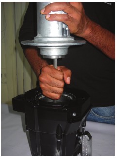
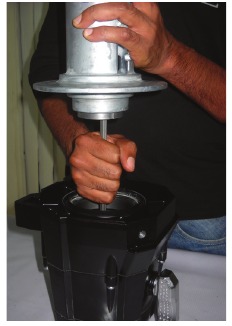
Remove motor sub assembly. Use a screwdriver if needed to move easily.

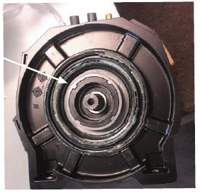
Remove and inspect motor side plastic drum bushing.

Check the drum bushing and drum support for excessive wear, replace if worn.
Inspect lip seal. Replace if damaged.
Stand winch on gear housing end.
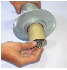
Remove aluminum motor coupler from the drum assembly.

 N O T I C E
If brake removal is required, go to BRAKE REMOVAL AND REPLACEMENT SECTION for brake removal procedures.
Remove the drum assembly from the gear train end of the winch.

Remove the drive shaft from the gear train end of the winch.
Remove and inspect transmission side drum bushing and seal.

Check the drum bushing and drum support for excessive wear, replace if worn. Inspect lip seal. Replace if damaged.
Remove the pan head cap screws.

Remove the drum support from the sub assembly.
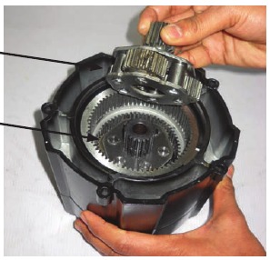
Remove gear-train housing from drum support. Use a screwdriver if needed.

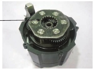
Remove the drive spline from the third stage carrier.

Remove the ring gear from the end housing.

Inspect teeth of ring gear. Replace if worn or damaged.
Note that the splined end of the third stage gear is facing up.

Remove the third stage carrier.
Inspect pin swages. Replace third stage carrier if any are loose or spun.
After removing the third stage gear you will see the second stage gear.

Remove the thrust washer. Inspect, replace if damaged or worn.
Remove the second stage planetary gear from the gear housing.
Remove the first stage gear.
Carefully inspect carriers. Replace if any gear damage is found.
Remove the loose first stage sun gear. Check for worn or chipped gear teeth.

Check all gears for excessive wear and replace if necessary.
Remove the free spooling clutch handle from the gear train by removing the screw M5 detent then lifting the handle out of the housing.

NOTE: This step does not apply to Zeon Platinum Winches. Proceed to next step.
Remove the O-ring seal and seal retainer, inspect the O-ring seal for wear.

NOTE: This step does not apply to Zeon Platinum Winches. Proceed to next step.
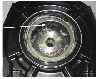
Remove retaining ring on the rotating ring gear.

Remove the rotating ring gear from the end housing.

Check all gears for excessive wear (outside diameter and clutch engagement features). Look for worn or chipped gear teeth. Replace if necessary.
NOTE: This ends disassembly for ZEON® Winches. Skip to Section Reassembly now.
NOTE: If you have a ZEON® Platinum continue on to the next Section Disassembly of ZEON® Platinum Winch Remote Clutch below to complete disassembly.
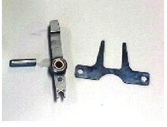
Disassembly of ZEON® Platinum Winch Remote Controlled Clutch
Remove cap screw

Remove pawl stop. Check for wear.

Replace if chipped or worn.
Remove five pan cap screws.

Remove end cap from gear train housing.

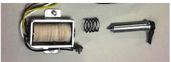
Remove the two pan head screws to release the clutch solenoid.

Remove finger spring and pawl.

Check all parts for wear. Replace if necessary.
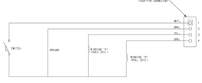
Check electrical integrity of solenoid assembly. Follow Solenoid coil specs below. Replace if necessary.
Solenoid coil specs:
- Resistance between terminal 2 and 3 to be 5.74ohm +/- 5%
- Resistance between terminal 2 and 4 to be 1.17ohm +/- 5%
- Resistance between terminal 2 and 1 to be 1Mohm with switch open
- Resistance between terminal 2 and 1 to be less than 1ohm
![]()
Re-assembly
Re-assembly for ZEON® Platinum Winch remote controlled clutch
If product is not a ZEON ® Platinum Winch, proceed to the next section.
Install finger spring and pawl.

Secure with two pan screws previously removed. Torque to 53-79 in. lbs.

Install plunger and spring into clutch solenoid.

Secure clutch solenoid assembly with two pan head screws previously removed. Torque to 53-79 in. lbs.

Ensure plunger moves freely, no binding.
Fit end cap to gear train housing.

NOTE: A new gasket must be used. Carefully seat wire harness seal.
Install the five pan head screws previously removed. Torque to 53-79 in. lbs.

Insert pawl stop.

Secure with pan head screw. Torque to 53-79 in. lbs.

Reassembly for ZEON ® Winch and ZEON ® Platinum Winch
NOTE: Pay particular attention to the steps as some may or may not apply to your specific winch.
Apply a light coat of machine oil to the inside of the gear housing where the sliding ring gear rides.

Install the rotating ring gear with the scalloped end down.

Install retaining ring.
Grease the o-ring seal, install the o-ring seal onto the gear housing, Then place the clutch lever into the hole in the housing.
NOTE: This step does not apply to Zeon Platinum Winches. Proceed to next step.

Install clutch lever while in the freespool position.
NOTE: The 2nd stage ring gear may need to rotate to allow clutch lever to be in the engaged position.
NOTE: This step does not apply to Zeon Platinum Winches. Proceed to next step.
Secure the clutch lever with the screw M5 detent.

NOTE: This step does not apply to Zeon Platinum Winches. Proceed to next step.
Apply a light coating of machine oil to the sun gear shaft.

Install the sun gear into the bushing in the end of the housing. Coat the inside of the ring gear teeth with grease until all spaces between the teeth are filled. DO NOT apply excessive amount.
Use a grade of moly-disulfide grease with good performance between -50ºF (-45.5ºC) and +125ºF (51.7ºC).

Completely ll the teeth of the first stage and second stage carrier assemblies with grease and place into the gear housing.

Use light grade machine oil on the three planetary gear bushings inside the carrier assembly.
It may help to align all the planetary gear teeth if you install the hex drive shaft into the first stage sun gear and rotate slightly as you slide the gears into place.

Install the second stages rotating the shaft to align the teeth. Remove the shaft to allow for installation of the drum support.
Install the thrust washer on to the gear housing. Note orientation.

Lightly grease and install the third stage planetary gear set on to the second stage assembly and trust washer.
N O T E
Make sure that the splined end of the third stage planetary is facing up.
Install the third stage ring gear on to the third stage planetary gear set and the housing.

Insert the drive spline into the third stage carrier.

NOTE: The third stage ring gear must engage gear pro le in drum support.
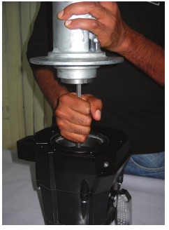
Fit the gear train onto the drum support.
The drum support will fit up to the gear train housing with almost no effort when parts are aligned. Do not force assembly.

NOTE: A new gasket must be used.
Attach the gear train to the drum support using ve pan head screws. Torque to 53-79 in. lbs.

Apply a light coating of grease to the inside of the drum bushing and lip seal and install into the drum support.
N O T E
For the bushing to t properly the slot in the bushing must t over the index tab in the drum support.
N O T I C E
If the brake has been removed from the drum, go to section 3-BRAKE REMOVAL AND REPLACEMENT for brake installation procedures.
With the brake installed in the drum, insert the hex drive shaft into the brake and then install the drum with the shaft, onto the gear train assembly.
You may need to spin the hex shaft to line it up with the sun gear in the gear housing.
Brake will not function properly if the coupler tangs are not positioned properly
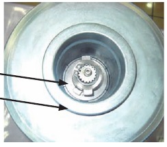
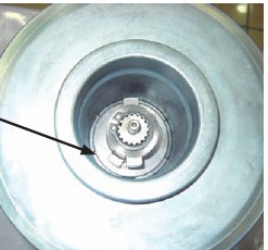
Install the aluminum motor coupler over the brake assembly with the internal tangs on the motor coupler at a 90 degree angle to the tangs on the cam follower of the brake assembly.
Cam Follower tang.
Apply a light coat of grease to outside of drum journal.
Apply a light coating of grease to the outside of the drum bushings and inside lip seals.
For the bushing to fit properly the slot in the bushing must fit over the index tab in the drum support.
Install the motor sub assembly to the drum.

Install the control assembly on the motor assembly and gear train assembly with the four pan head tap screws.

Torque the three motor terminal nuts to 70-97 in. lbs. Torque tie plate fasteners to 230-265 in. lbs.
Reattach the electrical cables from the control pack to the motor.

Torque 5.9 - 8.1 ft. lbs.
BRAKE REMOVAL AND REPLACEMENT
N O T I C E
Warn Industries does not offer individual replacement brake parts for the ZEON® Winches. The complete brake and drum assembly must be replaced.
N O T I C E
A drum/brake kit is needed to service brake system. The drum and brake must be replaced together.
Suggested Tools
These tools are suggested for the following procedures:
- 1 -7 /32" Hex Key Wrench
- Rubber Mallet.
Disassembly
NOTE: Some images shown in steps may not necessarily represent your actual product.
Remove the winch rope from the drum or secure it on the drum for ease of working.
Remove the drum from the winch as described in winch disassembly section.
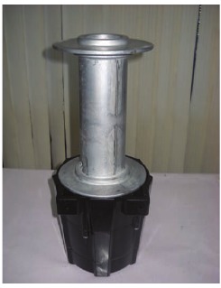
Set drum on solid working surface (table, bench, etc). then remove the aluminum motor coupler from the drum tube.

The brake unit is spring loaded. Should the brake unit unwind it will be necessary to replace it with a new brake assembly. Never attempt to rewind a brake unit that has come unwound.
There are two ways to remove the brake assembly from the drum.

Number 1: Pinch the brake tangs together and lift out. The friction material will be loose when the brake is removed from the drum.
Lock the brake tangs together with locking pliers or a clamp to re-vent the brake from coming unwound.
If the brake assembly will not slide out, set the drum on end and use a steel rod, drift pin or similar tool and push the brake out of the drum.
Number 2: Remove the brake assembly by pinching the brake tangs together, then partially slide the brake out of the motor end of the drum.

If the brake assembly will not slide out easily, set the drum on end and use a steel rod, drift pin or similar tool and push the brake out of the drum.
To prevent the spring loaded brake assembly from unwinding, use either a cardboard or steel tube with an internal diameter of 2 1/8" to hold the brake assembly together.

Remove the complete brake assembly from the drum.
Reassembly/ New Brake Installation
Set the drum assembly on a solid work surface and slide the brake unit through the cardboard sleeve into the drum about six inches.
N O T I C E
A drum/brake kit is needed to service brake system. The drum and brake must be replaced together.
With the brake installed in the drum, insert the hex drive shaft into the brake and then install the drum with the shaft on to the gear train assembly.
You may need to spin the hex shaft to line it up with the sun gear in the gear housing.
Brake will not function if the motor coupler tangs are not positioned properly.
Install the aluminum motor coupler over the brake assembly in the drum with the internal tangs on the coupler at a 90 degree angle to the tangs on the cam follower of the brake assembly.
Cam follower tang correctly installed.
Install the aluminum Motor coupler over the brake assembly in the drum with the internal tangs on the coupler at a 90 degree angle to the cams on the brake assembly.

Reinstall drum support and motor as outlined in the winch basic assembly instruction in REASSEMBLY section.

N O T E
Drum seals must be greased prior to drum installation. As drum is presented to drum seal, the drum must be gently rotated and angled to seat properly into lip seal.
ELECTRIC MOTOR & CONTROL PACK OVERVIEW AND WIRING REFERENCE

Overview Of Control Pack Operation
ZEON ® Winches
Electrical operation of the winch control assembly consists of a heavy-duty contactor and a DPDT switch in the remote control. When the remote is switched to either power-in or power-out one of the contactor coils is energized. This is accomplished in the remote by switching both the power and ground circuits. In the power-in mode, the green wire supplies power to the contactor coil and the brown wire provides ground.
ZEON ® Platinum Winches
Electrical operation of the winch control assembly consists of a contactor, a remote clutch and two auxiliary power drivers, all controlled by a wireless control module. In the power-in mode the green wire (contactor pin 1) triggers and the brown wire (contactor pin 2) grounds. In the power-out mode the white wire (contactor pin 3) triggers and the brown wire (contactor pin 2) grounds. In the free-spool mode power is applied to the green wire (4-pin connector pin 4) for 5 seconds, power is also applied to the yellow wire (4-pin connector pin 3) until free pool is deactivated. The brown wire (4-pin connector pin 2) is ground for the remote clutch. The white wire (4-pin connector pin 1) is feedback for the control module that the clutch engaged or disengaged. The auxiliary drivers when activated supply power to the red wire (aux plug pin 2) and ground the white wire (aux plug pin 1).
Always inspect wires/cables operating winch. Frayed, kinked or damaged wires/cables must be replaced immediately. Damaged components must be replaced before operation. Protect parts from damage.
Because of the large amounts of current needed to pull loads at the higher capacities we recommend using a ground cable the same size as the positive (+) battery lead. The ground cable should be attached directly to the bolt located on the underside of the motor housing from the three terminals and to the negative (-) battery terminal.
ZEON ® Winch Control Pack Wiring
Figure 4.1 is the basic wiring diagram of the ZEON® winch control pack. The redundant switching of the power and ground circuits provides safety against run on from a shorted contactor control circuit.

Figure 4.2 is the basic wiring diagram of the 5-wire remote control. The ve-wire remote is designed to control both the voltage side of the circuit as well as the ground. When the remote control is unplugged, the ground circuit is disconnected.

The drawing in gure 4.3 is for routing the wires in the control pack to prevent heat damage from the bus bars in a 12 VDC control pack.

- Contactor control wires must be secured as shown.
ZEON ® Platinum Winch Control Pack Wiring
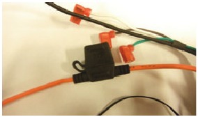
Figure 4.4 is the basic wiring diagram of the ZEON® Platinum Winch control pack. The control module has a 40A fuse to protect against high current overload draw by the aux channels or remote controlled clutch solenoid.

Fuse replacement
Open fuse holder.
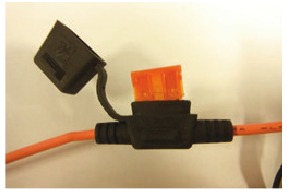
Remove old fuse.
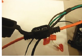
Apply Nyogel 760G on fuse holder terminals.
Install new fuse (40 amps). Ensure fully seated.
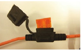
Close fuse holder.
Control Module Replacement
Unbolt power cable from (+) buss bar

Unscrew thermistor from (+) buss bar

Unbolt (+) buss bar from contactor, remove power wire

Disconnect blade connectors from contactor

Cut zip tie

Pull Ground wire through plastic grommet

Unscrew control module retention screw

Slide snap features out of their grooves

Remove control module

Re-assembly
Insert control module snap features into groves on baseplate

Install control module retention screw

Route wires as shown to avoid damage caused by buss bars

Install blade terminals onto contactor, ensure they are fully seated

Install power wire onto (+) buss bar using nut and lock washer

Install thermistor to (+) buss bar.

Route ground cable through plastic grommet

Install zip tie to secure wires to contactor to secure wires.

- Control wires must be secured with zip tie as shown.
Install power cable to +buss bar, route through plastic grommet

Advanced Wireless Remote Battery Replacement
Unscrew all 8 screws holding the remote halves together.

Separate the 2 remote halves.

Remove original gasket from remote.

Locate battery plug and note orientation.

Unplug battery and remove.

Plug battery in new battery, orient as shown.

Insert new seal in gland, ensure it is fully seated with no twists.

Place back on remote.

Tighten 8 screws to 1 Nm in a crisscross pattern.

WINCH TROUBLE SHOOTING GUIDE
| PROBLEM | POSSIBLE CAUSE | CORRECTIVE ACTION |
| Winch does not hold load |
| Remove all wire rope from drum and respool in the proper direction. (see directional label on drum support). |
| Refer to the Winch Operators Manual for the correct line pull rating for your winch. DO NOT EXCEED THE LINE PULL RATING SHOWN ON THE IDENTIFICATION LABEL | |
| Replace brake. Entire brake assembly must be replaced. Refer to this manual for winch brake replacement. | |
| Brake over heats and will not hold load. |
| Remove all wire rope and respool in the proper direction. (See directional label on drum support) |
| Refer to Winch Operators Manual for the line pull rating for your winch. DO NOT EXCEED LINE PULL RATING SHOWN ON IDENTIFICATION LABEL. | |
| Let brake cool for approximately 30 minutes. These winches are rated for intermittent duty operation only. As the load is increased, the duration of powerout cycles must be reduced to limit brake temperature. Allow adequate time for brake to cool between extended power-out cycles. | |
| Difficulty in spooling wire rope OFF drum by hand. |
| Rotate drum on winch and inspect for bent drum anges. A bent drum must be removed and replaced. See (DISASSEMBLY Section) drum removal instructions. |
| Remove drum from winch DISASSEMBLY Section). Inspect drum bushings and drum support for wear. | |
| Remove and inspect clutch ring gear, clutch shaft, and gear housing for burrs or damage. Remove burrs with le. Replace parts if necessary. (See DISASSEMBLY section for gear train disassembly). | |
| By connecting the hook to a load and alternately powering-in and powering-out, the wire rope will usually work itself free. DO NOT PUT YOUR HANDS NEAR THE WIRE ROPE OR FAIRLEAD WHEN ATTEMPTING TO FREE A BOUND ROPE. | |
| Check mounting hole dimensions. Follow mounting speci cations and procedures as described in the operator's manual. Be sure mounting surface is at to with in 0.020 inch. Be sure all mounting bolts are tight. | |
| Disassemble gear train, inspect and clean sliding ring gear, replace if necessary. | |
| Remove gear train. Clean all grease from machined surface of gear housing and ring gear. Apply light oil on machined surfaces. | |
| Winch lacks power, pulls slowly, stalls or will not run at all. |
| Attach ground cable to threaded hole in motor housing – not to a terminal. |
| Be sure all connections are tight and clean. | |
| Charge battery. | |
| Clean terminals. | |
| Replace with conventional automotive battery with minimum of 650 cold cranking amps rating. | |
| Connect contactor common (switched ground, brown wire). | |
| Check battery cables and motor cable leads for loose connections, worn or cracked insulation, and fraying or bare spots. Replace cable if necessary. | |
| Test winch operation with replacement remote control. Replace remote control if defective. | |
| Connect ground wire directly to negative battery terminal. | |
| Winch does not have the same pulling power as when it was new. | See All possible Causes for the previous problem | See corresponding Corrective Actions for the previous problem |
| When remote control switch is activated, only a "clicking sound" results and winch does not operate in either power-in or power-out mode. |
| See possible Cause a. and corresponding Corrective Action for the "Winch lacks power, pulls slowly, stalls or will not run at all" problem. |
| See the previous problem Possible Causes b. through e. and corresponding Corrective Actions. | |
| Replace motor. See DISASSEMBLY & ASSEMBLY Section. | |
| Replace motor. | |
| Electrical sparks appear around the motor or motor end housing. |
| See corresponding Corrective action. |
| Replace with conventional automotive battery with minimum of 650 cold cranking amps rating. | |
| When the remote control is activated, winch operates in only one direction. |
| Check remote control switch and cable. Replace if necessary. Check all connections inside control pack. Check all pins in plug and receptacle for damage. |
| Replace with conventional automotive battery with minimum of 650 cold cranking amps rating. | |
| Replace contactor | |
| ZEON PLATINUM ONLY | ||
| PROBLEM | POSSIBLE CAUSE | CORRECTIVE ACTION |
| Winch is not operating | Low wireless strength | Make sure your Advanced Wireless Remote Control is within range. |
| Wireless Remote Control Activation Switch is in the OFF position | Turn ON the Wireless Remote Control Activation Switch | |
| Winch control pack is under water. Wireless signal will not transmit under water. | Winch control pack needs to be above water to receive wireless signal. See www.warn.com for accessories. | |
| Remote controlled clutch does not disengage when requested | Tension or Load exists on the winch, preventing the clutch from disengaging. | Power-out winch until winch rope is no longer under load. |
| The remote controlled clutch is disconnected from the control pack. | Check the 4-pin remote controlled clutch connector on the back of the control pack to be sure it is rmly connected. | |
| The remote controlled clutch is damaged. | Contact WARN® customer service for further information. | |
| Remote will not operate | The remote battery is critically low. | Charge the remote battery See charging instructions. |
| Auxiliary will not turn on | Auxiliary is not connected | Check auxiliary connector and cables. |
| Auxiliary short circuit | Accessories wiring faulty; Accessory electrical load is to high. *Auxiliary systems must be rated for 12v and draw less than 16 amps. | Check wiring; reduce electrical load. |
| Wireless signal strength is low | Decrease distance between remote control and winch. | |
WARN INDUSTRIES, INC.
12900 S.E. Capps Road, Clackamas, OR USA
97015-8903, 1-503-722-1200,
FAX: 1-503-722-3000
Customer Service: 1-800-543-9276
Dealer Locator Service: 1-800-910-1122
International Fax: 1-503-722-3005
Documents / Resources
References
Download manual
Here you can download full pdf version of manual, it may contain additional safety instructions, warranty information, FCC rules, etc.
Advertisement


Need help?
Do you have a question about the ZEON and is the answer not in the manual?
Questions and answers