Table of Contents
Advertisement
Quick Links
Advertisement
Table of Contents

Subscribe to Our Youtube Channel
Related Manuals for Warn 685000


Summary of Contents for Warn 685000
- Page 1 Click Here To View Item at www.GapPower.com...
- Page 2 SERVICE GUIDE WARN PULLZALL 120v AC &100v AC P/N 685000 & 685001 REPAIR / REPLACEMENT INSTRUCTIONS TROUBLE SHOOTING GUIDE 986765A2.doc Page 1 of 50...
- Page 3 This guide uses NOTICE to call attention to important mechanical information, and Note: to emphasize general information worthy of special attention. Notice This guide has been provided for use by WARN Authorized Service Centers. Any other use is prohibited. Caution...
-
Page 4: Table Of Contents
CONTENTS 1. GENERAL DESCRIPTION 2. DISASSEMBLY AND ASSEMBLY 2.1. Suggested Tools 2.2. Housing 2.3. Gear Train Assembly 2.4. Motor 2.5. Wire Rope Assembly 2.6. Safety Hook 2.7. Tail Hook 2.8. Drum Assembly 2.9. Wiring Diagrams 2.10. Torque Specifications 3. PULLZALL TROUBLE SHOOTING 4. -
Page 5: General Description
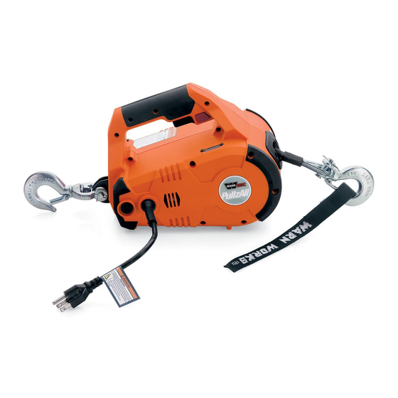
PullzAll 120v AC Specifications: 1. Part number 685000 & 685001. 2. Light weight and portable. Powerful 120 Volt AC Motor. - Page 6 986765A2.doc Page 5 of 50...
-
Page 7: Disassembly And Assembly
2 DISASSEMBLY AND ASSEMBLY 2.1 SUGGESTED TOOLS 1. Hammer 2. Snap ring plier 3. Allen key set 4. Screw driver 5. Cutting plier 6. Pin remover (Punch) 7. Insulation tape 8. Gloves 986765A2.doc Page 6 of 50... -
Page 8: Housing
2.2 HOUSING Before opening the Housing follow the below instructions: Power Cord Always unplug the product while rigging, when not in use or during maintenance and cleaning. 2.2.1 REMOVAL OF HOUSING Remove the screws (#6 x .75), Qty 7 from Handle. Remove the screws (#8 X 1.25), Qty 6 from the main body of the Housing. - Page 9 Keep the assembly on the work bench facing the Cover in the direction as shown in the figure. Remove the Plastic Housing -left hand from the assembly as shown in the figure. Remove the Main Chassis from the Plastic Housing - right hand and place it on the work bench.
- Page 10 2.2.2 ASSEMBLY OF HOUSING Install the Main Chassis in the Plastic Housing - right hand as shown in the figure. Install the Plastic Housing -left hand on the assembly as shown in the figure. Flip the assembly as show in the figure. 986765A1.doc Page 9 of 50...
- Page 11 Install the screws (#8 X 1.25), Qty 6 from the main body of the Housing. Install the screws (#6 x .75), Qty 7 near Handle. Note: When replacing the Housings with a Housing Service kit, be sure to affix ALL appropriate labels from the service kit onto the new housings, using the housings being replaced as a guide for placement of your new labels.
-
Page 12: Gear Train Assembly
2.3 GEAR TRAIN ASSEMBLY • If the gearsets are worn or damaged, the entire PullzAll must be replaced, no replacement parts are available. 2.3.1 GEAR TRAIN ASSEMBLY REMOVAL Remove Retaining Ring from Idler Gear. Remove Wear Washer from Idler Gear. Remove Retaining Ring from Helical Gear Press. - Page 13 Remove Helical Gear from Gear Housing. Remove 3 Cap Screws(#3 x .75) from Gear Housing through Left side Bracket of Chassis assembly. Remove Gear Housing from left side Bracket of Chassis assembly. Remove Carrier Assembly from Ring. 986765A1.doc Page 12 of 50...
- Page 14 Remove Ring Gear 51 T from left side Bracket P/N of Chassis assembly. 2.3.2 GEAR TRAIN REASSEMBLY Install Gear Train assembly after installation of Motor assembly. Insert Ring Gear 51 T on Left side Bracket of Chassis assembly as shown in the figure.
- Page 15 Install Ring Gear 48T P/N 73225 and Carrier Assembly P/N 73227 in Gear Housing P/N 75077. Install Gear Housing on Left side Bracket of Chassis assembly aligning dowel pins. Install 3 Cap Screws (#3 x .75) in Gear Housing through Left side Bracket of Chassis assembly.
- Page 16 Install Wear Washer on Helical Gear Press. Install Retaining on Helical Gear. Install Idler Gear on Gear Housing. Install Wear Washer and Retaining Ring on Idler Gear. 986765A1.doc Page 15 of 50...
- Page 17 2.3.3 INSPECTION OF GEAR TRAIN 1. Check each Idler Gear to make sure that all teeth are present in good condition. 2. Check each Sun Gear to make sure all teeth are present and in good condition. 3. Check each side of each Sun Gear to make sure there are no grooves from wear. Replace the Gear Set if worn.
-
Page 18: Motor
2.4 MOTOR 986765A1.doc Page 17 of 50... - Page 19 2.4.1 REMOVAL OF MOTOR Before removing the Motor follow the instructions given below: Remove the Gear Train assembly. Remove the 2 screws (#8 x 0.75) from Chassis assembly. Remove the left side cap screw and nut from Hawse Fairlead assembly. 986765A1.doc Page 18 of 50...
- Page 20 Remove cap screw from Chassis assembly as shown in the figure. Remove Left side Bracket from Chassis assembly. Remove Motor assembly from Chassis assembly after removal of Wiring leads 986765A1.doc Page 19 of 50...
- Page 21 2.4.2 ASSEMBLY OF MOTOR Connect all Wire leads from Motor assembly and install in to Chassis assembly as shown in the figure. Install Left side Bracket on Chassis assembly as shown in the figure. Install cap screw in Chassis assembly as shown in the figure.
- Page 22 Install the left side cap screw and nut from Hawse Fairlead assembly. Install 2 screws (#8 x 0.75) in Chassis assembly. 2.4.3 MOTOR INSPECTION • Visual inspection. • While assembling the Motor ensure that, Motor has been properly placed inside the End Housing and the screw had been properly tightened.
- Page 23 2.5 WIRE ROPE ASSEMBLY 2.5.1 REMOVAL OF WIRE ROPE Note: Prior to disassembly: 1. Spool out all Wire Rope. 2. Use of gloves is recommended while handling frayed or damaged Wire Rope. 3. Unplug unit before disassembly. Tasks: Disassemble the Drum and Wire Rope. Push the Wire in the direction of the arrow mark as shown in the figure.
- Page 24 Use the Pin remover (punch) to remove the Wire Rope and Stop Button from the Drum. Straighten the bent Rope and pull the Rope out of Drum hole in the arrow direction as shown. Remove the Hawse Fairlead from the Bracket of the Chassis.
-
Page 25: Wire Rope Assembly
2.5.2 ASSEMBLY OF WIRE ROPE Assemble the Hawse Fairlead to the Bracket of the Chassis. Tighten the cap screws with Allen key and opened end wrench. Keep the insulation tape to the edge of the Wire Rope. 986765A1.doc Page 24 of 50... - Page 26 Insert the Wire Rope into the Drum through the Hawse Fairlead. Pull the wire from the other end of the Drum hole. Bend the Wire Rope and insert in to the same hole in the direction shown in the figure. Pull the Wire Rope from the hole as shown in the figure.
- Page 27 Support one edge of the Wire and pull the other Wire as shown in the figure. Verify Wire Rope stop button is inserted into the loop as shown before pulling the Wire Rope tight. Hit with hammer, so that the Wire Rope will get in to the hole and tightens.
- Page 28 Check from the other side of the Drum whether the Wire Rope is perfectly assembled to the Drum. 986765A1.doc Page 27 of 50...
- Page 29 2.5.3 INSPECTION OF WIRE ROPE • Inspect the Wire Rope for signs of wear or damage. Worn and damaged parts must be replaced. • See the Rope for damage for kinks, cuts, knots, mashed or frayed portions and broken strands. •...
-
Page 30: Safety Hook
2.6 SAFETY HOOK 2.6.1 REMOVAL OF SAFETY HOOK To remove Safety Hook follow the below instructions: First straighten the bent end of the Cotter Pin by using Cutting plier and then pull out the Cotter Pin by holding head of the Cotter Pin with the help of cutting plier from the Pin. - Page 31 Remove the Pin from the Hook and Rope. Remove the Safety Hook from Wire Rope 986765A1.doc Page 30 of 50...
- Page 32 2.6.2 ASSEMBLY OF SAFETY HOOK To Reassemble Safety Hook follow the below instructions: Place the Safety Hook and align the mounting holes with the loop of the Wire Rope Insert the Pin through Safety Hook and Wire Rope loop. Insert the Cotter Pin inside the hole of the Pin and bend the ends of the Cotter Pin with the help of Cutting pliers.
- Page 33 2.6.3 INSPECTION • Inspect the Hook for signs of wear and damage. • Hook damage examples: cracks, twisted components, excessive opening, seat wear, loose or damaged safety latch or corrosion. 986765A1.doc Page 32 of 50...
-
Page 34: Tail Hook
2.7 TAIL HOOK Original Tailhook Assy Generation Tailhook Assy Service Part Tailhook Assy 986765A1.doc Page 33 of 50... - Page 35 2.7.1 REMOVAL OF TAIL HOOK To remove Tail hook follow the below instructions: Remove bolt and nut from the Chassis assembly through Tail Hook. Loose the cap screw with Allen key before removing the Tail Hook and Spacer Pin from Chassis assembly. 986765A1.doc Page 34 of 50...
- Page 36 2.7.2 ASSEMBLY OF TAIL HOOK To reassemble the Original Tailhook follow the below instructions: Tighten the cap screw after place Tail Hook and Spacer Pin between the Bracket holes. Assemble the bolt and nut. 986765A1.doc Page 35 of 50...
- Page 37 To reassemble the Second Generation Tail Hook follow the instructions 1. Place Spacer Bracket Chassis assembly with capscrew and then apply the torque. 2. Take the Tail Hook and align the mounting holes with the Spacer Bracket holes and Chassis assembly. 986765A1.doc Page 36 of 50...
- Page 38 3. Insert the Pin through the Hook assembly. 4. Insert the Cotter Pin inside the hole of the Pin and bend the ends of the Cotter Pin with the help of pliers. 2.7.3 TAIL HOOK INSPECTION • Inspect the Hook for signs of wear and damage •...
-
Page 39: Drum Assembly
2.8 DRUM ASSEMBLY • If the drum is worn or damaged, the entire PullzAll must be replaced, no replacement parts are available. 986765A1.doc Page 38 of 50... -
Page 40: Wiring Diagrams
2.9 WIRING DIAGRAMS 1. WIRING DIAGRAMS 2. REMOVAL 3. ASSEMBLY 4. INSPECTION Wiring diagram 74862B0 (with Rocker switch) Note: Older models had a circuit breaker instead of the Rocker switch. Wire Routing to the Circuit breaker is identical to the Rocker Switch. 986765A1.doc Page 39 of 50... - Page 41 WIRING DETAILS • Route black lead Wire from J3 terminal on Circuit Board through Wire guides up into handle to Trigger Switch. • Route black lead Wire from J2 terminal on circuit board through Wire guides up to Rocker Switch. •...
- Page 42 2.9.1 REMOVAL OF WIRING To remove the wiring follow the below instructions: Remove Circuit Breaker or Rocker Switch from Plastic Housing (right hand) and remove corresponding lead Wires. Circuit Breaker Shown. Rocker Switch replaced the Circuit Breaker on later models. Remove 2 Retaining Rings P/N 73742 to unlock Power Cord as shown in figure.
- Page 43 Remove the Wire leads from Trigger Switch. Remove green lead Wire from Chassis Ensure that all Wires are properly Connected. Push the Plastic Retainers out that secures the LED display. 986765A1.doc Page 42 of 50...
- Page 44 Remove the Load limiter Board Assy from Plastic Cover. Check all the connections for proper contact 986765A1.doc Page 43 of 50...
- Page 45 2.9.2 ASSEMBLY OF WIRING To reassemble the wiring follow the below instructions: Install Load limiter Board Assy to Right hand Plastic Housing. Install LED to Right hand Plastic Housing. Bolt green lead Wire as a ground to Chassis with the help of Allen key. 986765A1.doc Page 44 of 50...
- Page 46 Connect lead Wires to correct locations on the Trigger Switch and place the Trigger Switch into the Right hand Plastic Housing. Install direction Switch slider properly into the Housing slot related to the Trigger Switch. Make sure that all lead Wires are routed correctly and connected to Switch correctly.
- Page 47 Use 2 Retaining Rings to lock Power Cord with the Plastic Housing in opposite direction. Install Circuit Breaker or Rocker Switch to Right Plastic Cover and connect corresponding lead Wires. 2.9.3 INSPECTION OF WIRING • Visual Inspection. • Ensure that Switches have assembled correctly. Wiring is complete match the drawing. •...
-
Page 48: Torque Specifications
2.10 TORQUE SPECIFICATIONS 986765A1.doc Page 47 of 50... -
Page 49: Pullzall Trouble Shooting
3. PULLZALL TROUBLE SHOOTING PROBLEM POSSIBLE CAUSE CORRECTIVE ACTION 1.1 PullzAll does not Loose connection on Motor Be sure all connections are tight and power in or pulls terminals. clean. Do not let bottom nut or stud slowly. turn while tightening. Check the speed mode Change mode as required. - Page 50 Motor does not run. Faulty Trigger Switch Repair or replace Switch Defective Motor Replace Motor Loose connection of the Secure the Motor terminal and Wires to be Motor terminals. Wires. 1.6 Electrical sparks Switch held in power-in Replace Wiring harness PullzAll appear around position while PullzAll is Motor.
-
Page 51: Service Part List
4. SERVICE PART LIST ITEM NO. DESCRIPTION PART NO. Service Part -Motor assembly 120v AC 77914 (Includes Motor, Plastic Housing, Brushes & Screws) Service Part - Variable Speed Trigger,120v AC 77911 Service Part - Load limiter assembly, 120v AC 86354 (Includes LED Bezel, Screws and LED Retention Pins) Service Part - Wire rope assembly, PullzAll 76065...
Need help?
Do you have a question about the 685000 and is the answer not in the manual?
Questions and answers