
Related Manuals for Kübler A50


Summary of Contents for Kübler A50
- Page 1 D000084575.0002 – Index A Manual Draw-wire encoders A50 - Interchangeable installation...
- Page 2 Published by Kübler Group, Fritz Kübler GmbH Schubertstr. 47 78054 Villingen-Schwenningen Germany www.kuebler.com Application support Phone +49 7720 3903-849 +49 7720 21564 support@kuebler.com D000084575.0002 – Index A Document no. Document title Manual, Draw-wire encoders Language version English (EN) - German is the original version 05.11.2024, D000084575.0002 –...
-
Page 3: Table Of Contents
Table of contents Table of contents Table of contents Symbols used / warning and safety instructions 1. First steps ........................... 5 1.1 Unpacking and checking ....................... 5 2. Warnings ..........................6 3. Interchangable installation (encoder) ................7 4. Mounting or fastening the draw-wire encoder ..............9 4.1 Wire outlet options ........................ -
Page 4: Symbols Used / Warning And Safety Instructions
Symbols used / warning and safety instructions Symbols used / warning and safety instructions Classification This symbol, together with the signal word DANGER, warns against immediately imminent threat to life and health of persons. The non-compliance with this safety instruction will lead to death or severe adverse health effects. -
Page 5: First Steps
1 First steps First steps The Kübler Group, Fritz Kübler GmbH would like to thank you for the trust you have placed in us. This manual is intended to familiarize you with the installation and operation of our draw-wire encoders. Please read carefully before commissioning. -
Page 6: Warnings
2 Warnings Warnings Injuries due to contact (friction) with the measuring wire during operation Cuts or burns on the hands ► Do not touch the moving measuring wire during operation. Injuries and damage caused by opening the appliance The high stored energy of the drive spring can lead to injuries if handled incorrectly and / or the function can be partially or completely lost. -
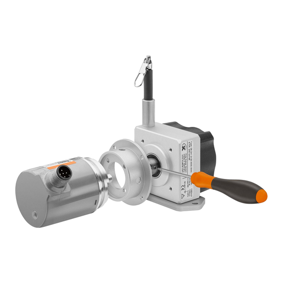
Page 7: Interchangable Installation (Encoder)
3 Interchangable installation (encoder) Interchangable installation (encoder) The option “Interchangeable installation” allows a fast and easy encoder assembly by the customer. Figure 1 A detailed description of the mounting procedure is shown in the following pictures. All incremental and absolute encoders are suitable that have a clamping flange with 36 mm diameter, a shaft diameter of 10 mm and a shaft length between 10 - 20 mm. - Page 8 3 Interchangable installation (encoder) Figure 2 1. Insert the rotary encoder into the clamping flange with the shaft in front. 2. Place the clamping flange on the draw-wire encoder. Figure 3 3. The mounting flange is attached to the cable pull sensor using the four axially arranged countersunk screws (Allen key 2.5 mm, 2 Nm).
-
Page 9: Mounting Or Fastening The Draw-Wire Encoder
4 Mounting or fastening the draw-wire encoder Mounting or fastening the draw-wire encoder Wire outlet options Figure 4 D000084575.0002 – Index A EN - 9... -
Page 10: Mounting Wire Outlet Top 0° And Wire Outlet Right 90
4 Mounting or fastening the draw-wire encoder Mounting wire outlet top 0° and wire outlet right 90° The encoder can be mounted using the mounting plate. Figure 5 Mounting wire outlet left 270° and wire outlet below 180° (bottom) The encoder has a modified mounting plate for wire exits on the left and below (bottom). Mounting the draw-wire encoder without mounting plate The following threaded holes are available for mounting by unscrewing the mounting plate: 2 x M4 und 2 x M5... -
Page 11: Maintenance
5 Maintenance Maintenance The devices are maintenance-free. If however, the rope is soiled due to adverse environmental conditions, it can be cleaned with a cloth drenched in resin-free machine oil. D000084575.0002 – Index A EN - 11... -
Page 12: Disposal
6 Disposal Disposal Always dispose of unusable or irreparable products in an environmentally friendly manner in accordance with the country-specific regulations and applicable waste disposal regulations. We will be happy to help you dispose of the products. See chapter ‚Contact‘ Environmental damage due to incorrect disposal Electrical waste, electronic components, lubricants and other auxiliary materials are subject to hazardous waste treatment. -
Page 13: Contact
7 Contact Contact You want to get in touch with us: Technical advice For technical advice, analysis or support during installation, Kübler is directly on site with its globally active application team. Support International (English-speaking) +49 7720 3903 849 support@kuebler.com Kübler Germany +49 7720 3903 849 Kübler Australia... - Page 14 Kübler Group Fritz Kübler GmbH Schubertstrasse 47 78054 Villingen-Schwenningen Germany Tel.: +49 7720 3903-0 Fax: +49 7720 21564 info@kuebler.com www.kuebler.com...
Need help?
Do you have a question about the A50 and is the answer not in the manual?
Questions and answers