
Related Manuals for Kübler Sendix Base KIS40


Summary of Contents for Kübler Sendix Base KIS40
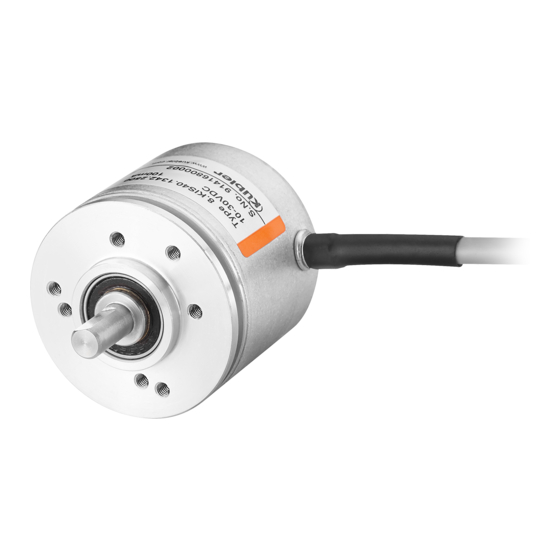
- Page 1 R60087.0009 - 03 ® Betriebsanleitung Sendix Base KIS40/KIH40 Operation Manual Instructions d'utilisation...
-
Page 2: Table Of Contents
Elektrische Installation ........Inhaltsverzeichnis 4.2.1 Allgemeine Hinweise für den Anschluss..4.2.2 Hinweise zur EMV gerechten Installation ..Dokument..............4.2.3 Anschluss Farbkodierung ......Allgemeine Hinweise ..........4.2.4 Anschließen der Anschlussdrähte ....Vorbemerkung ..........Instandhaltung............Zielgruppe............. Demontage ........... Transport / Einlagerung ........ Wiedermontage .......... -
Page 3: Dokument
1 Dokument 2 Allgemeine Hinweise Dies ist die Originalbetriebsanleitung, Ausgangssprache Lesen Sie dieses Dokument sorgfältig, bevor Sie Deutsch. mit dem Produkt arbeiten, es montieren oder in Be- trieb nehmen. Herausgeber Kübler Group, Fritz Kübler GmbH Schubertstraße 47 Diese Betriebsanleitung leitet das technische Personal des 78054 Villingen-Schwenningen Maschinen- und Anlagenherstellers bzw. -
Page 4: Transport / Einlagerung
2.3 Transport / Einlagerung • In Bereichen, in denen größere EMV-Ereignisse auftreten können, als in der benannten Norm definiert. Prüfen Sie die Lieferung unmittelbar nach Erhalt auf mögliche Transportschäden. Wenn Sie das Gerät nicht direkt einbau- 2.6 Mitgeltende Dokumente en, lagern Sie es am besten in der Transportverpackung ein. Achten Sie bei einer Lagerung des Drehgebers darauf, dass HINWEIS die Welle und der Kabelabgang stets frei von jeglicher Druck-... -
Page 5: Typenschild
3.2 Typenschild 3.3 Technische Daten Das Typenschild auf dem Produkt sieht beispielhaft wie folgt HINWEIS aus: Technische Daten Alle technischen Daten sowie die mechanischen und elektri- schen Kennwerte finden Sie in den Datenblättern der ent- sprechenden Variante des Gerätes, bei Sonderausführungen in der entsprechenden Angebots- / Kundenzeichnung des Produktes. -
Page 6: Allgemein
3.3.1 Allgemein Elektrische Kennwerte Mechanische Kennwerte Versorgungsspannung 5 V DC 5 … 30 V DC Maximale Drehzahl ** 4500 min 10 … 30 V DC Arbeitstemperatur ** -20°C ... +70°C Versorgungsspannung ge- Class 2 [-4°F … +158°F] mäß UL 1310 Schutzart gemäß EN 60529 IP64 Stromaufnahme (ohne Last) je nach gewähltem Drehge- bertyp Verschmutzungsgrad ge- mäß EN 61010 Schutzklasse ge- III (PELV) mäß EN 61140 Aufstellhöhe... -
Page 7: Installation
4 Installation ACHTUNG Drehgeber nicht modifizieren und Welle nicht verändern 4.1 Mechanische Installation Die Genauigkeit des Drehgebers wird beeinträchtigt und die ACHTUNG Funktion von Lager und Dichtung kann teilweise oder voll- ständig verloren gehen. Schädigung des Gerätes durch Transport oder Lagerung •... -
Page 8: Kupplungen
Schrauben und Schraubverbindungen ACHTUNG Für alle Schraubverbindungen wird, wenn nicht anders be- Stator und Rotor nicht starr mit der Applikation verbin- schrieben, ein Reibwert von 0,14 vorausgesetzt. Für Schrau- ben wird, wenn nicht anders beschrieben, eine Festigkeits- klasse von 8,8 (metrisch) oder Grade 5 (imperial) vorausge- Der Drehgeber wird mechanisch überbestimmt und nimmt setzt. -
Page 9: Montagehinweis Für Drehgeber Mit Hohlwellenausführung
c) Befestigen Sie den Drehgeber an den im Flansch vorgese- 4.1.5 Kabelführung henen Gewindebohrungen. HINWEIS d) Richten Sie die Kupplung auf den Wellen aus, verschrau- ben Sie die Kupplung ohne Vorspannung. Kabelführung e) Sichern Sie die Schrauben gegen Lösen, siehe Kapitel Verlegen Sie das Kabel des Sensors frei von Zug, so dass Schraubensicherung. -
Page 10: Elektrische Installation
4.2 Elektrische Installation HINWEIS Keine offenen Kabeladern 4.2.1 Allgemeine Hinweise für den Anschluss Schließen Sie vor der Inbetriebnahme alle benötigten Kabela- ACHTUNG dern / Steckverbinder an. Isolieren Sie alle nicht benötigten Enden der Ausgangssignale einzeln, um Kurzschlüsse zu Zerstörung des Gerätes vermeiden. -
Page 11: Anschluss Farbkodierung
4.2.3 Anschluss Farbkodierung HINWEIS Teilweise sind die Kabel über eine Farbkodierung, teilweise Erdung des Drehgebergehäuses über eine Zahlenkodierung realisiert. Die Farben sind wie Der Kabelschirm ist intern mit dem Gebergehäuse verbun- folgt abgekürzt: den. Achten Sie bei der Anbindung über eine Statorkupplung Kurzzeichen Farbe Kurzzeichen Farbe darauf, dass diese ausreichend gut leitend ist. -
Page 12: Instandhaltung
• Alle Sicherheitshinweise des Kapitels Installation [} 7] kön- 5 Instandhaltung nen eingehalten werden. In rauen Umgebungen empfehlen wir eine regelmäßige In- • Alle beschriebenen Montageschritte des Kapitels spektion auf festen Sitz und auf mögliche Beschädigungen Installation [} 7] können umgesetzt werden. des Gerätes. -
Page 13: Anhang
7 Anhang 7.1 Einschränkungen HINWEIS Drehgeber mit Kabelabgang Drehgeber mit direktem Kabelausgang sind aufgrund des Ka- belmaterials (PVC im Standard) nur bis -30°C [-22°F] einsetz- IMG-ID: 85632267 bar. Falls Sie einen erweiterten Bereich benötigen, sprechen Bei der Messung am Flansch fließen sowohl die Umgebung- Sie uns an. -
Page 14: Kontakt
Reparatur-Service / RMA-Formular 8 Kontakt Für Rücksendungen verpacken Sie das Produkt bitte ausrei- Sie wollen mit uns in Kontakt treten: chend und legen das ausgefüllte „Formblatt für Rücksendun- Technische Beratung gen“ bei. Für eine technische Beratung, Analyse oder Unterstützung www.kuebler.com/rma bei der Installation ist Kübler mit seinem weltweit agierenden Schicken Sie Ihre Rücksendung, unter Angabe der RMA-Re- Applikationsteam direkt vor Ort. - Page 15 Electrical Installation ........Table of Contents 4.2.1 General Information for the Connection..4.2.2 Information for EMC-Compliant Installation .. Document..............4.2.3 Connection Color Coding......General Information ..........4.2.4 Connecting the Connecting Wires ....Preliminary Remark ........Maintenance............Target Group ..........Disassembly ..........Transport / Storage........
-
Page 16: Document
1 Document 2 General Information This is the English translation of the original operation manual Please read this document carefully before working in German language. with the product, mounting it or starting it up. Publisher Kübler Group, Fritz Kübler GmbH Schubertstraße 47 These operating instructions guide the technical personnel of 78054 Villingen-Schwenningen... -
Page 17: Use According To The Intended Purpose
When storing the encoder, make sure that the shaft and the 2.6 Other Applicable Documents cable outlet are always free from any load. NOTICE The device must be stored at a dry and dust-free location, in compliance with the technical data, see chapter Technical Data Technical Data [} 18]. -
Page 18: Technical Data
NOTICE Observe the configuration The performance characteristics and the mechanical design of the product depend on the selected configuration (accord- ing to order code). 3.3.1 General Mechanical values IMG-ID: 18014398693268363 Maximum rotational speed ** 4500 min Serial number Terminal Assignment Operating temperature ** -20°C ... +70°C Type and order code Observe the... -
Page 19: Approvals
UL - Underwriters Laboratories – RoHS: Directive 2011/65/EU • Compliance with the British Directives: UL approval File no. E224618 – EMC: Regulations S.I. 2016/1091 – RoHS: Regulations S.I. 2012/3032 Relevant standards UL 61010-1 Indoor use, outdoor use pos- The declaration of conformity and all certificates relating to sible, not designed for direct the product can be found on the homepage. -
Page 20: General Information For The Installation
4.1.1 General Information for the Installation ATTENTION Do not connect the stator and the rotor rigidly to the ap- ATTENTION plication Do not disassemble or open the device The encoder would be mechanically constrained and thus The function of the measuring system might be lost partly or damaged. -
Page 21: Couplings
Screws and screwed connections d) Align the coupling on the shafts, screw the coupling without preload. Unless otherwise specified, a friction coefficient of 0.14 is re- e) Secure the screws against loosening, see chapter Screw quired for all screwed connections. Unless otherwise spe- Retention. -
Page 22: Electrical Installation
Wiring NOTICE When wiring the facility, pay attention to proper cable routing. General safety instructions • Separate the wiring into power groups such as motor/power Make sure that the whole plant remains switched off during supply lines and signal and data lines. the electrical installation. -
Page 23: Information For Emc-Compliant Installation
• Preferably connect the shield on both sides with low imped- NOTICE ance to the protective earth (PE), e.g.on the device and/or on the evaluation unit. In the event of potential differences, Traction relief the shield must only be applied on one side. Always mount all cables with traction relief. -
Page 24: Connecting The Connecting Wires
4.2.4 Connecting the Connecting Wires 5.1 Disassembly To dismount the device, proceed in the reverse order of the ATTENTION assembly, see chapter Installation [} 19]. Destruction of the electronics 5.2 Reassembly When confectioning the sensor cable, always take care to en- Reassembling the device is only permitted under the follow- sure sufficient ESD protection. -
Page 25: Annex
Dispose of disassembled device components as follows: • Metal components in the scrap metal. • Electronic components in the electrical waste. • Plastic parts in a recycling center. • Sort and dispose of the other components depending on the material type. 7 Annex IMG-ID: 85632267 7.1 Limitations... -
Page 26: Contact
Repair service / RMA form 8 Contact In case of returns, please package the product sufficiently Sie wollen mit uns in Kontakt treten: and attach the completed "Returns form". Technical advice www.kuebler.com/rma Kübler's worldwide applications team is available on site all Send your return, stating the RMA reference, to the following over the world for technical advice, analysis or installation address:... - Page 27 Installation électrique ........Sommaire 4.2.1 Informations générales pour le raccorde- ment.............. Document..............4.2.2 Instructions pour une installation selon les prescriptions CEM ........Informations générales.......... 4.2.3 Code des couleurs du raccordement.... Remarque préliminaire ......... 4.2.4 Branchement des fils de raccordement ..Groupe cible ..........
-
Page 28: Document
1 Document 2 Informations générales Traduction française des instructions d'utilisation originales Lisez attentivement ce document avant de travailler en langue allemande. avec le produit, de le monter ou de la mettre en service. Editeur Kübler Group, Fritz Kübler GmbH Schubertstraße 47 Ces instructions d'utilisation guident le personnel technique 78054 Villingen-Schwenningen du constructeur et de l'exploitant de la machine ou de l'instal-... -
Page 29: Transport / Entreposage
2.3 Transport / Entreposage • Dans des zones où des événements CEM plus importants que ceux définis dans la norme indiquée peuvent survenir. Inspectez la livraison dès réception pour détecter tout éven- tuel dommage dû au transport. Si l'appareil ne doit pas être 2.6 Autres documents applicables monté... -
Page 30: Plaque Signalétique
3.2 Plaque signalétique 3.3 Caractéristiques techniques Exemple d'une plaque signalétique du produit : AVIS Caractéristiques techniques Toutes les données techniques, ainsi que les caractéristiques mécaniques et électriques, se trouvent dans les fiches tech- niques de la variante correspondante du produit ; pour les exécutions spéciales, elles se trouvent sur le dessin projet / client correspondant du produit.. -
Page 31: Généralités
3.3.1 Généralités UL - Underwriters Laboratories Caractéristiques mécaniques Homologation UL N° de dossier E224618 Normes prises en compte UL 61010-1 Vitesse de rotation maximale 4500 min Utilisation en intérieur, utilisa- tion à l'extérieur possible, Température de travail ** -20°C ... +70°C non prévu pour le rayonne- [-4°F … +158°F] ment UV direct. -
Page 32: Installation
• Homologation selon UL pour l’espace économique nord- 4 Installation américain. • Conformité avec les directives européennes : 4.1 Installation mécanique – CEM : Directive 2014/30/UE – RoHS : Directive 2011/65/UE PRUDENCE • Conformité avec les directives britanniques : Dommages à l'appareil dus au transport ou à l'entrepo- –... - Page 33 PRUDENCE PRUDENCE Ne pas modifier le codeur, ni son arbre Ne pas relier de manière rigide le stator et le rotor avec l'application. La précision du codeur en serait affectée, et une partie ou l'ensemble des fonctions du palier et du joint seraient per- Le codeur serait mécaniquement surdéterminé, ce qui l'en- dues.
-
Page 34: Accouplements
Vis et liaisons vissées c) Fixer le codeur dans les taraudages prévus à cet effet dans la bride. Sauf indication contraire, un coefficient de friction de 0,14 est d) Aligner l'accouplement sur les arbres, visser l'accouple- requis pour toutes les liaisons vissées. Sauf indication ment sans précontrainte. -
Page 35: Pose Des Câbles
4.1.5 Pose des câbles 4.2 Installation électrique AVIS 4.2.1 Informations générales pour le raccordement Pose des câbles Poser le câble du capteur de façon à éviter tout effort de trac- PRUDENCE tion, afin qu'aucun effort supplémentaire ne s'exerce sur le Destruction de l'appareil système de mesure. -
Page 36: Instructions Pour Une Installation Selon Les Prescriptions Cem
4.2.2 Instructions pour une installation selon les AVIS prescriptions CEM Instructions applicables lors de l'installation Exigences pour les câbles Pour le raccordement de l'appareil, respecter les instructions • N'utiliser comme câble de raccordement pour l'appareil que d'utilisation et les consignes de sécurité correspondantes du du câble blindé... -
Page 37: Code Des Couleurs Du Raccordement
• Relier le blindage à la terre de protection (PE) de préfé- 4.2.4 Branchement des fils de raccordement rence des deux côtés avec une impédance basse, p. ex. au niveau de l'appareil et/ou de l'unité d'évaluation. En pré- PRUDENCE sence de différences de potentiel, le blindage ne doit être connecté... -
Page 38: Démontage
• Déconnecter ensuite physiquement les lignes d'alimentation AVIS en énergie. • Enlever les consommables et les produits auxiliaires, ainsi Dommages à l'environnement en cas d'élimination erro- que les matériaux à traiter encore présents, du système de née mesure. Les déchets électriques, les composants électroniques ainsi que les lubrifiants et autres consommables sont soumis à... -
Page 39: Définition De La Mesure De Température
7.1.1 Définition de la mesure de température AVIS Dans certaines conditions, la température ambiante maxi- Température de composants connectables male admissible doit être limitée. Les codeurs se caracté- risent ainsi aussi par une température de travail maximale in- Lors du choix des accessoires, en particulier de la connec- cluant plusieurs composants. -
Page 40: Contact
Service Réparation / Formulaire RMA 8 Contact Pour les retours, merci d'emballer le produit de manière suffi- Vous voulez entrer en contact avec nous : sante et de joindre le « Formulaire de retour » rempli. Conseil technique www.kuebler.com/rma L'équipe d'application Kübler est à vos côtés sur site dans le Envoyer votre retour, en indiquant la référence RMA, à... - Page 41 Notizen / Notes...
- Page 44 Kübler Group Fritz Kübler GmbH Schubertstr. 47 D-78054 Villingen-Schwenningen Germany Phone +49 7720 3903-0 Fax +49 7720 21564 info@kuebler.com www.kuebler.com...
Need help?
Do you have a question about the Sendix Base KIS40 and is the answer not in the manual?
Questions and answers