Table of Contents
Advertisement
Quick Links
Download this manual
See also:
Operating Manual
®
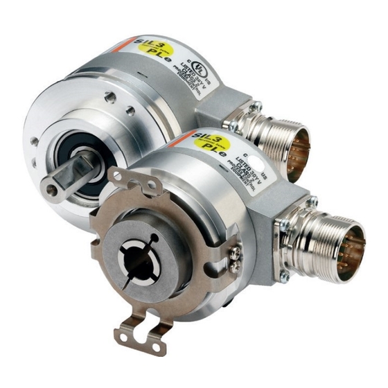
Sendix
Drehgeber für Funktionale Sicherheitstechnik
Encoders for Functional Safety
Codeurs pour la sécurité fonctionnelle
Encoder per la sicurezza funzionale
Encoder para la seguridad funcional
Buy: www.ValinOnline.com | Phone 844-385-3099 | Email: CustomerService@valin.com
SIL
Betriebsanleitung
Operating Manual
Instructions d'utilisation
Manuale d'uso
Instrucciones de uso
Advertisement
Table of Contents

Related Manuals for Kübler Sendix SIL Series


Summary of Contents for Kübler Sendix SIL Series
- Page 1 ® Sendix Drehgeber für Funktionale Sicherheitstechnik Encoders for Functional Safety Codeurs pour la sécurité fonctionnelle Encoder per la sicurezza funzionale Encoder para la seguridad funcional Betriebsanleitung Operating Manual Instructions d’utilisation Manuale d’uso Instrucciones de uso Buy: www.ValinOnline.com | Phone 844-385-3099 | Email: CustomerService@valin.com...
-
Page 2: Copyright Information
Copyright Information © Fritz Kübler GmbH. All rights reserved. The contents of this documentation are protected by copyright by the Fritz Kübler GmbH Company. This documentation may not be altered, expanded, reproduced or circulated to third parties, without the prior written agreement of the Firma Fritz Kübler GmbH Company. The brands and product names mentioned in this document are trademarks or registered trademarks of their respective owners. -
Page 3: Table Of Contents
Table of Contents 1. General information ........................4 1.1 Targeted personnel ......................4 1.2 Symbols used ........................4 1.3 Transport / Storage ......................4 1.4 Intended use........................4 1.5 Further applicable documents ..................4 2. Scope of delivery / Device structure ..................5 2.1 Function of the encoder.................... -
Page 4: General Information
1. General information Please read these operating instructions carefully before going to work with the safe encoder, mounting it or commissioning it. These operating instructions guide the technical staff of the machine manufacturer or of the machine user for safe assembly, electrical installation, commissioning, and for operating the safe encoder. -
Page 5: Scope Of Delivery/Device Structure
2. Scope of delivery/Device structure 2.1 Function of the encoder ® The encoder types of the Sendix SIL family supply an incremental signal or a combination of an absolute and an incremental signal. The incremental information is provided by an analogue sine/cosine signal. Depending on the variant, the resolution per revolution is 1024 or 2048 sine/cosine periods. - Page 6 8.5853 FS2 . X X 2 X Order code Shaft version Type f g h Flange Code Options (Service) 1 = clamping flange, ø 58 mm, IP65 B = SSI, Binary 1 = no options C = BiSS-C, Binary 2 = Status LED Shaft (ø...
-
Page 7: Variants Overview
2.3 Variants overview Family Encoder type Safety function Safety class 5814FS2 SS1, SS2, SOS, SIL2 (EN 61800-5-2) SLA, SAR, SDI, SLI, 5834FS2 SLS, SSR, SSM PLd (EN ISO 13849-1) 7014FS2 5853FS2 SS1, SS2, SOS, SLA, SAR, SDI, SLI, 5863FS2 SLS, SSR, SSM, 5873FS2 SLP, SCA 5883FS2... -
Page 8: Example Of A Name Plate
2.4 Example of a name plate A name plate with the following information is affixed on the encoder: • Type description/Order code • Interface code (only for absolute encoders) • Serial number • Manufacturer and address • Supply voltage • Current consumption •... -
Page 9: Functional Safety
3. Functional safety The safety-rated Sendix ® SIL encoders are designed for the implementation of safety-related functions regarding rotational speed, direction of rotation and position. This requires a higher-level safe encoder controller, since the encoder cannot trigger on its own initiative actions such as initiating a safe condi- tion using its encoder-internal diagnostics. -
Page 10: Encoder Mounting
3.3.2 Safe absolute encoder function In order to obtain safe information with the encoder regarding the absolute position, the controller counts the incremental pulses (relative position) and compares the result with the absolute positions also provided by the encoder. This allows detecting a deviation of both signals. The indicated position is continuously verified by a comparison of the digital position data with the sine/cosine signals that are also constantly being counted and compared by the controller. -
Page 11: Data Transmission
4. Data Transmission 4.1 Sine and Cosine signals – – A – A = Cosine ; B – B = Sine – The analogue signals must be measured differentially, i.e. A minus A gives the cosine, B minus – – –... -
Page 12: Ssi Data Transmission
4.1.2 Differential signal measurement Measured differentially, the sine and cosine signals have an amplitude of 1 Vss, with a phase-shift of 90°. Depending on the variant, the resolution of the incremental track is 1024 or 2048 sine/cosine periods per revolution. -0,5 4.2 SSI data transmission The absolute position is transmitted via the SSI interface to the controller in the form of a digital data... -
Page 13: Biss-C Data Transmission
4.3 BiSS data transmission The BiSS-C-Interface features bidirectional isochronous communication between sensors, actuators and industrial controllers. This purely digital link and its protocol have been designed for maximum performance, transmission reliability and security. Without affecting the payload data of measurements or interfering with control cycles, the commu- nication protocol incorporates a permanent, bidirectional access to slave registers. -
Page 14: Operation In Explosive Areas
For SSI and BiSS absolute tracks Encoder Controller Data + Data - Clock + Clock - Z = 120 5. Operation in explosive areas ® The explosion-proof encoders Sendix SIL 70xxFSx have extended operation-related requirements, which are described in the separate installation instructions. Buy: www.ValinOnline.com | Phone 844-385-3099 | Email: CustomerService@valin.com... -
Page 15: Mechanical Installation Of The Encoder
6. Mechanical installation of the encoder 6.1 General mounting information The encoder must not be disassembled or modified, either in total or in part. No subsequent machining should be carried out on the shaft (grinding, sawing, drilling, etc.). This would impair the accuracy of the encoder and damage the bearings and shaft seals. - Page 16 6.1.1 General mounting instructions for solid shaft encoders • Check the shafts for offset. • Protect the tolerance-compensating element during mounting from excessive bending and from damage. • Align the coupling on the shafts, and tighten without preload. The connection between encoder and drive shaft should be configured in such a way that any break- age of the connection can be excluded.
-
Page 17: Fastening
6.2 Fastening You will find the technical drawing with complete dimensioning in the data sheets of the corresponding encoder. 6.2.1 Solid shaft encoder The solid shaft encoder is fastened with at least three M3 screws through the threaded holes provided in the flange;... - Page 18 [1.50] [1.50] [1.95] 6.2.2 Drehgeber mit Konuswellenausführung 6.2.2 Tapered shaft encoder Die Befestigungsschraube der Konuswelle muss mit 3 Nm angezogen werden. Für die The fastening screw of the tapered shaft must be tightened with a torque of 3Nm. The stator coupling Befestigung der Statorkupplung müssen vier M3 Schrauben mit 1 Nm angezogen und gegen is fastened with four M3 screws tightened with a torque of 1 Nm and secured against loosening.
- Page 19 6.2.3 Hollow shaft encoder The fixing screw of the clamping ring must be tightened with a torque of 2.5 Nm. The torque pin must be screwed onto an M4 threaded pin, and tightened with a torque of 3 Nm. The screw connection must be secured against loosening.
- Page 20 67,5 entspricht. [2.2] [2.2] [2.66] Max. zulässige Toleranzen der Wellenverbindung: 6.2.4 ATEX solid shaft encoder - Axialversatz: < +/- 0,25 mm 6.2.4 ATEX-Drehgeber mit Vollwellenausführung The shaft encoder is fastened with at least three M4 screws through the threaded holes provided in - Radialversatz: <...
-
Page 21: Electrical Installation Of The Encoder
7. Electrical installation of the encoder Please always disconnect the power supply before connecting or disconnecting the signal line. Comply with the corresponding operating instructions of the external drive system/controller when connecting the encoder. 7.1 EMC Information • Use only shielded twisted-paired conductors as encoder cables. •... -
Page 22: Terminal Assignment
7.3 Terminal assignment The cables are made partly with a colour coding and partly with a numerical coding. The following abbreviations are used for the colours: WH: White BN: Brown GN: Green YE: Yellow GY: Grey PK: Pink BU: Blue RD: Red BK: Black VT: Violet... - Page 23 7.3.2 Incremental encoder (ATEX) Type of connection Cable – – Signal: Number: 1, 2, A, B Signal: Number: Shield Case Encoder Power Supply +V DC Encoder ground GND (0V) Protective earth (Shield) Shield: Cable shield Case: Encoder housing – A, A Channel A, Cosine signal –...
-
Page 24: Commissioning The Encoder
7.3.4 Absolute encoder (ATEX) Type of connection Cable Signal: Number: 1, 2, A, B – – Signal: Number: Shield Case Encoder Power Supply +V DC Encoder ground GND (0 V) C+, C-: Clock signal D+, D-: Data signal SET: Set input DIR: Direction input Protective earth (Shield) -
Page 25: Guidelines
8.3 Guidelines Power-on delay After switching on, the device requires a time of approximately 150 ms before valid data can be read. SET button The encoder can be set to zero at any position by means of a High signal on the SET input or by pressing the SET button (can be operated only with a pen or a thin item). -
Page 26: Disposal
9.3 Disposal Always dispose of unusable or irreparable devices in compliance with the waste disposal regulations in force. We will be glad to help you for disposing of these devices. Contact us. 9.4 Service Address Kübler Group Fritz Kübler GmbH -ServiceCenter- Schubertstrasse 47 D-78054 Villingen-Schwenningen... -
Page 27: Approvals
® Characteristic safety values for the Sendix SIL 58xxFS3 and 70xxFS3 encoders Characteristic safety values Relevant standards EN ISO 13849-1/EN 61800-5-2, EN 61508 Classification PLe/SIL 3 System structure 2-channel (cat. 4/ HFT = 1) value 1,09 x 10 Service life 20 years Characteristic values for the controller for Sendix ®... -
Page 28: Checklist For Start-Up
12. Checklist for start-up Mounting (see Mounting information) The encoder has been installed with mounting elements supplied by the Fritz Kübler GmbH com- pany. The load on the encoder shaft, as a result of mounting/installation, is kept as low as possible. The installation dimensions specified for the encoder have been strictly observed.
Need help?
Do you have a question about the Sendix SIL Series and is the answer not in the manual?
Questions and answers