Chapters
Table of Contents
Troubleshooting

Related Manuals for EGT P-27/75V St Curved


Summary of Contents for EGT P-27/75V St Curved
- Page 1 GAMING MACHINE HARDWARE USER MANUAL (rev. 1.1.) *The manufacturer shall reserve its right to modify and amend the item and this documentation without prior notification of the customers. ©2017, Euro Games Technology Ltd.
-
Page 2: Revision History
HARDWARE REVISION HISTORY Rev.1.0. - an initial document version Rev.2.1. - a new version of the document with the following changes: A new point II.2. GAMING MACHINE MOUNTING INSTRUCTION on pages. 15 - 26 in CHAPTER II. INSTALLATION is added, as the points: Multimedia Chair Mounting Instruction and Top Lamp Mounting Instruction are removed because the information there is added in the new point. -
Page 3: Signs Used
HARDWARE SIGNS USED WARNING! Warns about specific conditions or situations of/in the gaming machine, which require due attention. NOTE! Gives important or additional information of the gaming machine, software or the game. ©2017, Euro Games Technology Ltd. -
Page 4: Table Of Contents
HARDWARE CONTENTS CHAPTER I. INTRODUCTION І.1. General Description…………………………………………………………….. Technical Specifications and Dimensions……………………………………. І.2. І.3. Operating Conditions…………………………………………………………... І.4. Transportation…………………………………………………………………… І.5. Safety and Precaution Measures……………………………………………... CHAPTER II. INSTALLATION ІІ.1. Visual Inspection………………………………………………………………. ІІ.2. Gaming Machine Mounting Instruction…….………………………………… ІІ.3. Gaming Machine Installation Requirements………………………………… CHAPTER ІІІ. GAMING MACHINE SERVICE ІІI.1. - Page 5 HARDWARE IV.9. Meter Module………………………………………………………………….. IV.10 Signal Lights Controller………………………………………………………. IV.11 Decorative Lighting…………………………………………………………… IV.12 Electronic Key Reader……………………………………………………….. IV.13 Speakers………………………………………………………………………. IV.14 Door Switches………………………………………………………………… CHAPTER V. GAMING MACHINE TROUBLESHOOTING V.1. Troubleshooting………………………………………………………………. V.2. Error Messages………………………………………………………………. V.2.1. Events, Only Registered in All Events Log……………………………….. V.2.2. Warnings………………………………………………………………………. V.2.3.
-
Page 6: Chapter I. Introduction
HARDWARE CHAPTER I. INTRODUCTION І.1. General Description…………………………………………………………….. І.2. Technical Specifications and Dimensions……………………………………. І.3. Operating Conditions…………………………………………………………... І.4. Transportation…………………………………………………………………… І.5. Safety and Precaution Measures……………………………………………... ©2017, Euro Games Technology Ltd. -
Page 7: I.1. General Description
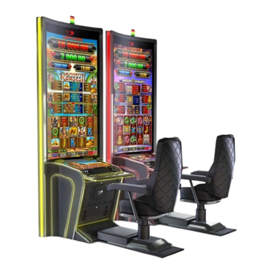
HARDWARE I.1. GENERAL DESCRIPTION P-27/75V St Curved gaming machines (hereinafter so referred to as "Machines") are designed for use in casinos and gambling halls. The series is developed on the basis of the Exciter III Gaming Platform, specially created for Euro Games Technology (EGT) and complied with the newest requirements of the gaming industry. -
Page 8: I.2. Technical Specifications And Dimensions
Before switching on the machine for the first time, please carefully read and understand this User Manual. I.2. TECHNICAL SPECIFICATIONS AND DIMENSIONS Manufacturer: EURO GAMES TECHNOLOGY Ltd., Bulgaria Type: EGT-VS18 Power Supply Voltage: 100 - 240 V ~ Current: 7.6-3.2A Consumption: ... - Page 9 HARDWARE Weight : 620 kg Height: cabinet - 3000 mm chair - up to 1350 mm Width: 1160 mm Depth: without chair - 990 mm with chair - up to 1950 mm Fig.I.2 Dimensions of P-27/75V St Curved Gaming Machine ©2017, Euro Games Technology Ltd.
- Page 10 HARDWARE Fig.I.3 Dimensions of Multimedia Chair Weight: 100 kg Height: 1310-1350 mm Width: 720 mm Depth: 945 mm ©2017, Euro Games Technology Ltd.
-
Page 11: I.3. Operating Conditions
HARDWARE I.3. OPERATING CONDITIONS P-27/75V St Curved gaming machines are designed and manufactured to keep their operability at the following conditions: Ambient temperature: from +10С° to +30С° Relative humidity: from 20% to 80% Vertical operation position +10%... - Page 12 HARDWARE The power cord of the gaming machine shall always be disconnected from the socket, when any repairs or servicing are performed at open main door. In case of power cord damage, it shall be replaced by a special cord or cord set, supplied by the Manufacturer or its representative.
-
Page 14: Chapter Ii. Installation
HARDWARE CHAPTER II. INSTALLATION ІІ.1. Visual Inspection………………………………………………………………. ІІ.2. Gaming Machine Mounting Instruction…….………………………………… ІІ.3. Gaming Machine Installation Requirements………………………………… ©2017, Euro Games Technology Ltd. - Page 15 HARDWARE II.1. VISUAL INSPECTION Before installation the machine shall be visually inspected for possible transportation damages. WARNING! The Manufacturer shall not bear liability for damages occurred upon transportation of the Gaming Machine. II.2. GAMING MACHINE MOUNTING INSTRUCTION II.2. 1. TOOLS REQUIRED Tool Type Star wrench...
- Page 16 HARDWARE Fig. II.1. Fig. II.2. WARNING! The connection cable to the multimedia chair has NOT to pass over the "Multimedia chair beam" (marked in blue in Fig. II.2.) ©2017, Euro Games Technology Ltd.
- Page 17 HARDWARE 2. Mounting of the Gaming Machine Back to Gaming Machine Body The gaming machine back is positioned in vertical position. The two modules are positioned against each other. They are approached to the limit, in an effort to ensure maximum fit of the mounting holes. The gaming machine back is fixed to the body via 4 pcs.
- Page 18 HARDWARE Фиг. II.5. 3. Top Lamp Mounting 3.1. The service cover CSVIP2.04.14.00.00.00 dismantling – remove 4 pcs. DIN967 M4x8 Screw - Fig. II.6. Fig. II.6. ©2017, Euro Games Technology Ltd.
- Page 19 HARDWARE 3.2. The top lamp electrical connection - The top lamp is connected to the connector mounted on the back (on the outside of the ceiling - Pos. 1 in Fig. II.7.) (see the gaming machine electrical diagram). The grounding conductor of the top lamp is passed through the back inside through the provided hole (Pos.
- Page 20 HARDWARE 3.3. Top lamp mounting to the gaming machine back – it is fixed by 4 pcs. DIN 7981 M3.5x9.9 Screw- Fig. II.9. Fig. II.9. 3.4. The service cover CSVIP.04.14.00.00.00 mounting – in reverse order of dismantling. 4. Electrical Connection of the Gaming Machine Back and Body 4.1.
- Page 21 HARDWARE 4.2. Electrical connection of the back of the cabinet to its body - All power and communication cables are connected to the corresponding connectors of the cabinet divider according to the electrical diagram of the gaming machine - Fig. II.11.
- Page 22 HARDWARE Fig. II.12. Fig. II.13. 4.4. Lower service cover CSVIP2.04.10.00.00.02 mounting – in a reverse order of the dismantling ©2017, Euro Games Technology Ltd.
- Page 23 HARDWARE 5. Multimedia Chair Mounting 5.1Mounting the top "seat" to the base of the multimedia chair - Place the chair base on the floor. The upper part (aligned horizontally) is placed on the axis of the base shock-absorber - Fig. II.14. Fig.
- Page 24 HARDWARE 5.2. Multimedia chair electrical connection to the gaming machine 5.2.1. Plug the connectors between the base and the top of the chair - disassemble the connector cover, plug the connector and then install the cover of the multimedia chair – Fig. II.15. Fig.
- Page 25 HARDWARE 5.2. Multimedia chair electrical connection to the gaming machine body – Fig. II.16. Fig. II.16. ©2017, Euro Games Technology Ltd.
- Page 26 HARDWARE 5.3. Multimedia chair mounting to the gaming machine body – the multi- media chair base is shoved under the gaming machine step until stops - Fig. II.17. Fig. II.17. ©2017, Euro Games Technology Ltd.
- Page 27 HARDWARE II.3. GAMING MACHINE INSTALLATION REQUIREMENTS In order to ensure proper operation of the machine the preliminary opera- tions, described below shall be performed: Place the machine in vertical position; Upon installation ensure at least 10 cm cooling space behind the back of the machine;...
-
Page 28: Chapter Ііі. Gaming Machine Service
HARDWARE CHAPTER ІІІ. GAMING MACHINE SERVICE ІІI.1. Control Keys……………………………………………………………………. ІІI.2. Credit Forming…………………………………………………………………. ІІI.3. Credit Clear…………………………………………………………………….. ІІI.4. Jackpot Payout……………………………………………...…………………. ІІI.5. Machine reservation and release……………………………………………. ІІI.6. Signal lights lighting modes………………………………………………….. III.7. Component Maintenance…………………………………………………….. ©2017, Euro Games Technology Ltd. - Page 29 HARDWARE III.1. CONTROL KEYS Access to the credit forming screen, service functions and accounting of the machine may be preformed by use of either mechanical or electronic keys. The system recognizes 4 types of keys: ATTENDANT - attendant’s mechanical/electronic key by which player’s credit ...
- Page 30 HARDWARE Fig. III.1 Credit addition can be performed: From the Screen Keyboard: 1. Dial the necessary number by touching the digit keys on the touchscreen keyboard. If a wrong digit is chosen, press <- ; 2. Press Add button; 3. If new Current Credit value is wrong, press Cancel and enter again; 4.
- Page 31 HARDWARE III.3. CREDIT CLEAR Credit zero reset and payout thereof may be performed only if the game is in bet mode after pressing a CASH OUT button. At pressing a CASH OUT button the credit may be paid out by Attendant (handpay), via thicket printer depending on settings of the gaming machine.
- Page 32 HARDWARE The visible part may be won if the player hits the winning jackpot combination according to the game rules. After the win of the visible value, the hidden value is shown as a new visible value. A valid address should be set in the machine settings and that the machine participates for LAP progressive jackpot should be indicated.
- Page 33 HARDWARE The jackpot win splashes are only greeting. Depending on the machine set- tings, the jackpot splash can be cleared automatically after defined time or by At- tendant key. The amounts won from jackpots may be added to the credit meter or be paid by hand (handpay).
- Page 34 HARDWARE III.6. SIGNAL LIGHTS LIGHTING MODES The signal lights are mounted on the top of the machine. Top ( Left ) Lamp Hand Pay Middle Lamp Open Door Yellow Bottom ( Right ) Lamp Tilt / Change Green They indicate the following conditions: 1.
-
Page 35: Iii.7. Component Maintenance
Description: Blow the dust away from the fun and the processor radiator using a mighty air stream. Clean only when the power is switched off! For prevention can address to the nearest EGT service. Recommended Maintenance Period: monthly. Cleaning: Clean the dust from the outside of the fan. Use a soft brush and vacuum cleaner. - Page 36 HARDWARE III.7.5. Ticket printer Description: Upon normal operation accumulation of dust on the paper might reduce printing quality. Recommended Maintenance Period: Depending on ambient conditions. In normal conditions the cleaning shall be carried out each 6 months. At severe operation conditions, such as polluted and/or dusty environment, it is recommended to perform cleaning more often.
-
Page 38: Chapter Iv. Hardware Components
HARDWARE CHAPTER IV. HARDWARE COMPONENTS IV.1. General Description of Components…………………………….….……….. 39 IV.2. Power Distributor Unit and Power Supply Units………………..…………... 45 IV.3. Exciter III - Specialized Gaming Platform……………...……………………. 46 Monitors and Touchscreen……………………………………………….…... 47 IV.4. IV.5. Multimedia Chair………………………………………………….……………. 47 IV.6. Bill Validator………………………………………………………………..…… 49 IV.7. -
Page 39: Iv.1. General Description Of Components
HARDWARE IV.1. GENERAL DESCRIPTION OF COMPONENTS Fig. IV.1. Front View of P-27/75V St Curved Cabinet with Closed Main Door ©2017, Euro Games Technology Ltd. - Page 40 HARDWARE Fig. IV.2. Inside Body View of P-27/75V St Curved Cabinet with Opened Main Door ©2017, Euro Games Technology Ltd.
- Page 41 HARDWARE Fig. IV.3. Inside Body View of P-27/75V St Curved Cabinet with Opened Main Door ©2017, Euro Games Technology Ltd.
- Page 42 HARDWARE Fig. IV.4. Back View of P-27/75V St Curved Cabinet with Removed Backs ©2017, Euro Games Technology Ltd.
-
Page 43: Description Of Components
HARDWARE DESCRIPTION OF COMPONENTS 1. Signal Lights (Top Lamps) 30. Electromechanical Locks (4 pieces) (optional) 2. EGT Logo 31. Decorative RGB Light Strips 4. 75’’ Curved Portrait Upper Monitor 2 32. Bill Validator Entrance 5. Multimedia Chair 33. Electronic Key Reader 6. - Page 44 HARDWARE The machine consists of five main parts: body, main door, upper part of 75” curved vertical monitor, back, and multimedia chair. IV.1.1. Body - Pos. 11 in Fig. IV.1. The body is the main part of the cabinet, inside of which the most of electronic machine components are located.
-
Page 45: Iv.2. Power Distributor Unit And Power Supply Units
- supply the backlights of the upper 75" curved monitor; Power Distributor Units (PDU): EGT Distribution Box 220V - “Distribution Box 8-Ports V1.4 Module” - Pos. 48 in Fig. IV.3 - supplies input voltage to: the Power Supply Units; ©2017, Euro Games Technology Ltd. -
Page 46: Iv.3. Exciter Iii - Specialized Gaming Platform
HARDWARE 12V and 24 V Distributor - “12V & 24V Distributor V 1.0” - Pos. 46 in Fig. IV.3; 12V Distributor - “12V Distributor V 1.0” - Pos. 53 in Fig. IV.4; IV.2.2. Technical Parameters Main Power Supply Units (PSUs) Parameter Value 100 ÷... -
Page 47: Iv.4. Monitors And Touchscreen
HARDWARE IV.4. MONITORS AND TOUCHSCREEN IV.4.1. Location in the Machine: - Pos. 4 and 13 in Fig. IV.1. IV.4.2. Type: Monitors: 75" vertical curved monitor - EG750C01609G - Pos. 4 in Fig. IV.1. 27" TFT monitor EG270001609G and touchscreen - Pos. 13 in Fig. IV.1. IV.4.3. - Page 48 HARDWARE Fig. IV.5. ©2017, Euro Games Technology Ltd.
-
Page 49: Iv.6. Bill Validator
HARDWARE IV.6. BILL VALIDATOR (OPTIONAL) IV.6.1. Location in the Machine: Bill Validator Entrance - Pos. 32 in Fig. IV.1., Bill Validator Door - Pos. 28 in Fig. IV.1. and Bill Validator - Pos. 38 in Fig. IV.2. IV.6.2. Type: CashCode MFL (Fig. IV.6.), JCM UBA-10-SS (JCM UBA-14- SS) or JCM iPro-100-SS (Fig. - Page 50 HARDWARE NOTE! The Bill Validator JCM UBA-14-SS can be used as well but it has to support serial interface RS232 and protocol ID-003. In case of using JCM UBA-14-SS an adapter Bill Level Adapter has to be used as well. This adapter converts bipolar signals into unipolar signals. Fig.
- Page 51 HARDWARE JCM UBA-10-SS Electrical parameters Value Power Supply Voltage: 12V DC ± 5% Standby 0.3 A Current consumption Operating mode 1.6 A Communication Interface RS232 Storage Temperature Environment Parameters -20°C ÷÷Value +60°C Operation Temperature +5°C ÷ +50°C Operating Relative Humidity 30% ÷...
- Page 52 HARDWARE MEI Advance SCN8347 MEI SC8307 and Electrical parameters Value Power Supply Voltage: 12 ÷ 28V DC ± 5% Standby 0.45 A Current consumption Operating mode 1.25÷3.0 A RS232 Communication Interface Environment Parameters Value Operation Temperature 0°C ÷ +60°C Operating Relative Humidity 5% ÷...
- Page 53 HARDWARE IV.6.5. Components Fig. IV.11. Fig. IV.12. Components of CashCode MFL Components of JCM UBA-10-SS Fig. IV.13. Components of Ardac Elite ©2017, Euro Games Technology Ltd.
- Page 54 HARDWARE Fig. IV.14. Components of MEI SC8307 Update the software of a MEI SC8307 bill validator by a hand held device Portable Programming Module (PPM). ©2017, Euro Games Technology Ltd.
- Page 55 HARDWARE Fig. IV.15. Components of JCM iVizion - SS A. Acceptor Unit M. Transport Unit Release Lever B. Front Upper Guide Access Lever (Acceptor Unit) N. Power ON LED (Green) C. Bezel (Option) - use from JCM iPro model! O. USB (mini-B) Software Download/...
- Page 56 HARDWARE IV.6.6. Collecting Bills IV.6.6.1. Collecting bills from CashCode MFL - 1 - - 2 - - 3 - Fig. IV.16. CashCode MFL Collecting Bills Open bill validator door. Push the lever, pointed by the small arrow on Fig.IV.16-1 and pull the cassette out.
- Page 57 HARDWARE Open Bill validator door. Hold the cassette handle and pull it in direction, pointed by the arrow on Fig. IV.17-1. Open the cover and take the bills (Fig. IV.17-2). Put back the cassette into the housing. IV.6.7. Removing Jammed Bills IV.6.7.1.
- Page 58 HARDWARE IV.6.8. Configuring the Bill Validator IV.6.8.1. Configuring CashCode MFL CashCode MFL configuration is done by setting switches, located at the rear end of the validating head, under a transparent plastic cover. Fig.IV.20. CashCode MFL Setting switches location ©2017, Euro Games Technology Ltd.
- Page 59 HARDWARE CashCode MFL operates in two basic modes: validation and service. Defining settings, operating mode and enabled denominations is performed by two groups of switches - SW1 and SW2 (Fig. IV.20., Fig. IV.21. and Fig. IV.22.) Fig. IV.21. CashCode MFL SW1 Setting switches condition Switch Denomination 1 enabled Denomination 1 disabled...
- Page 60 HARDWARE Parameters Switch Orientation of the bill SW 2.1 Four-way One-way SW 2.2 Not used Not used Interface communication speed SW 2.3 9600 bps 19,200 bps Operating Mode SW 2.4 Service Mode Validation Mode For additional information on switch features and explanations, please see CashCode MFL User Manual.
- Page 61 HARDWARE IV.6.8.3. Configuring Ardac Elite Two similar groups Bank 1 and Bank 2 of switches are located, which are shown below (Fig. IV.24.) Fig. IV.24. Ardac Elite Setting switches condition To select serial interface RS 232, determine the ID003 Baud Rate - 9600, and enable barcode reading, the following switches have to be in given position: Bank 2, switch 4 - ON, Bank 2, switch 5 - OFF...
-
Page 62: Iv.7. Ticket Printer
HARDWARE IV.7. TICKET PRINTER (OPTIONAL) IV.7.1. Location in the Machine: Pos. 39 in Fig. IV.2. IV.7.2. Тype: Ithaca Epic 950/950L, FutureLogic GEN2 or FutureLogic GEN2 Universal, JCM Global GEN5. Fig. IV.27. Ithaca Epic 950 Ticket Printer Fig. IV.28. Ticket Printer FutureLogic GEN2 FutureLogic GEN2 Universal Fig. - Page 63 HARDWARE IV.7.3. Purpose of Use: Prints vouchers and tickets. IV.7.4. Technical Parameters a) Ithaca Epic 950 Ticket Printer parameters: Electrical parameters Value Power Supply Voltage 24V DC ± 10% Current Consumption At 24V and 25% black max 2.2 А Communication interface RS232 Environment Parameters Value...
- Page 64 HARDWARE c) FutureLogic GEN2 Universal Ticket Printer parameters: Electrical parameters Value Power Supply Voltage 24V DC ± 10% Current Consumption At 24V and 25% black max 2.7А Communication interface RS232 Environment Parameters Value Operation Temperature 5°C ÷ 50°C Storage Temperature -20°C ÷...
- Page 65 HARDWARE IV.7.5. Loading tickets a) Loading tickets in Ithaca Epic 950 Ticket Printer Fig. IV.30. Loading tickets in Ithaca Epic 950 Ticket Printer 1. Load tickets into the ticket supply tray, making sure that the Black Dot is positioned as shown in Fig. IV.30. 2.
-
Page 66: Iv.8. Keyboard Controller And Keyboard Panel
HARDWARE IV.8. KEYBOARD CONTROLLER AND KEYBOARD PANEL IV.8.1. Location in the Machine: Keyboard Controller - Pos. 42 in Fig. IV.2. and Keyboard Panel - Pos. 12 in Fig. IV.1. IV.8.2. Type USB Keyboard Controller IV.8.3. Purpose of Use USB Keyboard Controller: ... - Page 67 HARDWARE CASH OUT (B11) - а button for credit cash-out procedure starting. First it ─ transfers the win to the credit meter (ends the game) and then starts the procedure for cash-out the credit. SERVICE - a button for staff calling; ─...
- Page 68 HARDWARE IV.8.4.2. OLED keyboard - Optional Fig. IV.33. Keyboard panel - 16-button OLED keyboard IV.8.4.2.1. Programmable Keyboard Controller - technical parameters Number of buttons - 16 in two sizes: 1,1" / 96х64 dots 1,6" / 128х64 dots ...
-
Page 69: Iv.9. Meter Module
HARDWARE Fig. IV.34. Keyboard buttons on the armrests of the chair IV.9. METER MODULE IV.9.1. Location in the Machine: Pos.20 in Fig. IV.1. IV.9.2. Type: Counters Vega IV.9.3. Purpose of Use counts the impulses, transferred by the control platform to the appropriate mechanical meters;... -
Page 70: Iv.10 Signal Lights Controller
+12V, 0.2A max IV.11. DECORATIVE LIGHTING IV.11.1. Location in the Machine and Type: Includes: White light for EGT logo (Pos. 2 in Fig. IV.1.), bill validator entrance and meters module; Red light for EGT logo on the cabinet back; ... -
Page 71: Iv.12 Electronic Key Reader
HARDWARE IV.12. ELECTRONIC KEY READER AND SOCKET IV.12.1. Location in the Machine: Socket for electronic keys - Pos. 14 in Fig. IV.1. and EGT iButton Reader - Pos. 33 in Fig. IV.2. IV.12.2. Type: EGT iButton Reader. DS9092 Socket;... -
Page 72: Chapter V. Gaming Machine Troubleshooting
HARDWARE CHAPTER V. GAMING MACHINE TROUBLESHOOTING V.1. Troubleshooting………………………………………………………………. V.2. Error Messages………………………………………………………………. V.2.1. Events, Only Registered in All Events Log……………………………….. V.2.2. Warnings………………………………………………………………………. V.2.3. Non-fatal Errors………………………..………….…………………………. V.2.4. Fatal Errors………………………...………………………………………... ©2017, Euro Games Technology Ltd. -
Page 73: Troubleshooting
HARDWARE V.1. TROUBLESHOOTING External features Possible cause Solution Fuse burned out Replace fuse Power Cord Replace power cord Nothing lights up Main Power Supply Unit Check PSU LED. Replace PSU. (PSU) Defective button Replace the button Buttons don’t work Problems with connection to Check keyboard controller con- keyboard controller nections. - Page 74 HARDWARE Bill 100 accepted - Logged when a bill of par value 100 is accepted. Bill 2 accepted - Logged when a bill of par value 2 is accepted. Bill 20 accepted - Logged when a bill of par value 20 is accepted. Bill 200 accepted - Logged when a bill of par value 200 is accepted.
- Page 75 HARDWARE Drop door closed - Logged when the drop door is closed. EEPROM data error - Logged when NVRAM is cleared. Gamble entered - Logged when Gamble is entered. The won amount at Gamble entering is logged. Gamble exited - Logged at Gamble exit. The value of the amount won is displayed. Game has ended - Logged when the game is over.
- Page 76 HARDWARE Power off bill stacker door opened - Logged at bill stacker door opening at machine power off. Date and time of first door opening and opening counts are logged. Power off bill validator door access - Logged at Bill Validator door access at machine power off.
-
Page 77: Warnings
HARDWARE V.2.2. Warnings Warnings are errors, which are displayed on a green rectangle on the game screen. They may be cleared with Attendant key. ©2017, Euro Games Technology Ltd. - Page 78 HARDWARE Bill acceptor hardware failure - Solution = Call attendant - Appears when bill validator is damaged. Disconnected counter lamp - Solution = Check counter lamp. Disconnected keyboard lamp - Solution = Check keyboard LEDs. Disconnected top lamp - Solution = Check top lamps. Low backup battery - Discharged Battery of NVRAM - Solution = Change battery.
-
Page 79: Non-Fatal Errors
HARDWARE V.2.3. Non-fatal Errors Non-fatal errors are displayed on a blue rectangle on the game screen. The error is cleared when its cause is solved. ©2017, Euro Games Technology Ltd. - Page 80 HARDWARE Bill jammed - Solution = Call attendant. Bill stacker door opened - Solution = Close bill stacker door. Bill stacker jam - Solution = Call attendant. Bill stacker opened - Solution = Close bill stacker. Bill validator door opened - Solution = Close Bill validator door. Card cage opened - Solution = Close card cage.
-
Page 81: Fatal Errors
General error - Appears at a critical problem in the machine NOTE! In case of fatal general error it is necessary to connect to the EGT service and report the error code, written in the box and additional information in the lower right corner of the screen. -
Page 82: Chapter Vi. Attachments
HARDWARE CHAPTER VI. ATTACHMENTS VI.1. Modular Diagram of Components…………………………………………. VI.2. Electric Wiring Diagrams………………………………………………..….. VI.3. Connectors of Exciter III Connectors Board ……………..……………… ©2017, Euro Games Technology Ltd. - Page 83 HARDWARE VI.1. MODULAR DIAGRAM OF COMPONENTS ©2017, Euro Games Technology Ltd.
- Page 84 HARDWARE VI.2. ELECTRIC WIRING DIAGRAMS ©2017, Euro Games Technology Ltd.
- Page 85 HARDWARE ©2017, Euro Games Technology Ltd.
- Page 86 HARDWARE ©2017, Euro Games Technology Ltd.
- Page 87 HARDWARE VI.3. CONNECTORS OF EXCITER III CONNECTORS BOARD BH40S 2x20 pin male PIN No Signal Name PIN No Signal Name T RXD4 T TXD4 T RXD7 T TXD7 T RXD5 T TXD5 T RXD6 T TXD6 T RXD2 T TXD2 T RXD3 T TXD3 DIN0...
- Page 88 HARDWARE INTRUSION SWITCHES MOLEX 7x2pin Mini-fit Straight PIN No Signal Name PIN No Signal Name INTRUSION0# INTRUSION1# INTRUSION2# INTRUSION3# INTRUSION4# INTRUSION5# INTRUSION6# Serial Ticket Printer MOLEX 3x2pin Mini-fit Straight PIN No Signal Name PIN No Signal Name COM9 Rx +24V COM9 Tx EXT_DIN11 (Coin Acc.
- Page 89 EXT_DIN2# (ADMIN) EXT_DIN3# (OUNER) J12,J13 EGT Progressive Net RJ45 PIN No Signal Name EGT NET DATA A LINE EGT NET DATA B LINE EGT NET +12V EGT NET +12V EGT NET GND EGT NET GND ©2017, Euro Games Technology Ltd.
-
Page 90: Audio Outputs
HARDWARE Cabinet FANS CviLux CI3103P1V00 PIN No Signal Name +12V AUDIO OUTPUTS MOLEX 2x2pin Mini-fit Straight PIN No Signal Name PIN No Signal Name SPKR FL+ SPKR FL- SPKR FR+ SPKR FR- POWER OUTPUT AMP 350211 PIN No Signal Name/Current +5V/1.5A +12V/1.5A AUDIO INPUT... -
Page 91: Contacts
Head Office Address 4 Maritsa Str. Vrana-Lozen-Triugulnika Pancharevo Region 1151 Sofia, BULGARIA EGT Technical Support - Head Office Phone: +359 2 890 24 68 Fax: +359 2 890 24 88 Mobile: +359 896 71 02 72 e-mail: service@egt-bg.com; parts@egt-bg.com EGT Sales - Head Office...
Need help?
Do you have a question about the P-27/75V St Curved and is the answer not in the manual?
Questions and answers