Table of Contents
Advertisement
Quick Links
Advertisement
Table of Contents
Troubleshooting

Related Manuals for EGT P-42V Up Curved


Summary of Contents for EGT P-42V Up Curved
- Page 1 HARDWARE P-42V Up Curved Gaming Machine HARDWARE USER MANUAL Rev. 2.0. *The manufacturer shall reserve its right to modify and amend the item and this documentation without prior notification of the customers. ©2017, Euro Games Technology Ltd. ©2017, Euro Games Technology Ltd.
- Page 2 HARDWARE REVISION HISTORY Rev.1.0. - an initial document version Rev.2.0. - a new version of the document with the following changes: The Electric Wiring Diagrams are updated; A new model of ticket printer is added: JCM Global GEN5; ...
- Page 3 HARDWARE SIGNS USED WARNING! Warns about specific conditions or situations of/in the gaming machine, which require due attention. NOTE! Gives important or additional information of the gaming machine, software or the game. ©2017, Euro Games Technology Ltd.
-
Page 4: Table Of Contents
HARDWARE CONTENTS CHAPTER I. INTRODUCTION І.1. General Description…………………………………………………………….. І.2. Technical Specifications and Dimensions……………………………………. І.3. Operating Conditions…………………………………………………………... І.4. Transportation…………………………………………………………………… І.5. Safety and Precaution Measures……………………………………………... CHAPTER II. INSTALLATION ІІ.1. Visual Inspection………………………………………………………………. II.2. Opening and Closing of Main Door……….…………………………………. ІІ.3. Top Lamp Mounting…………………………………………………………... ІІ.4. - Page 5 HARDWARE IV.13. Door Switches…………………………………………………….. CHAPTER V. GAMING MACHINE TROUBLESHOOTING V.1. Troubleshooting………………………………………………………………. V.2. Error Messages………………………………………………………………. V.2.1. Events, Only Registered in All Events Log……………………………….. V.2.2. Warnings………………………………………………………………………. V.2.3. Non-fatal Errors………………………..………….…………………………. V.2.4. Fatal Errors………………………...………………………………………... CHAPTER VI. ATTACHMENTS VI.1. Modular Diagrams of Components…………………………………..……. VI.1.1. Modular Diagrams of Components - Variant 1……………..……. VI.1.2.
-
Page 6: Chapter I. Introduction
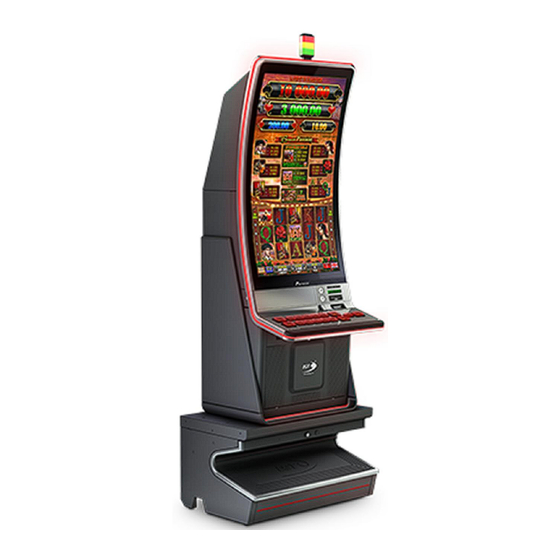
HARDWARE CHAPTER I. INTRODUCTION І.1. General Description…………………………………………………………….. І.2. Technical Specifications and Dimensions……………………………………. І.3. Operating Conditions…………………………………………………………... І.4. Transportation…………………………………………………………………… І.5. Safety and Precaution Measures……………………………………………... ©2017, Euro Games Technology Ltd. - Page 7 HARDWARE I.1. GENERAL DESCRIPTION P-42V Up Curved gaming machines (hereinafter so referred to as "Machines") are designed for use in casinos and gambling halls. The series is developed on the basis of the Exciter III Gaming Platform, specially created for Euro Games Technology (EGT) and complied with the newest requirements of the gaming industry.
- Page 8 Before switching on the machine for the first time, please read careful- ly and understand this User Manual. I.2. TECHNICAL SPECIFICATIONS AND DIMENSIONS Manufacturer: EURO GAMES TECHNOLOGY Ltd, Bulgaria Type: EGT-VS16 Power Supply Voltage: 100 - 240V ~ Current: 4.8-2.0A Consumption: ...
- Page 9 HARDWARE Fig.I.2 Dimensions of P-42V Up Curved Gaming Machine Weight: 186 kg Height: 1763 mm Width: 624 mm Depth: 607 mm ©2017, Euro Games Technology Ltd.
- Page 10 HARDWARE I.3. OPERATING CONDITIONS P-42V Up Curved gaming machines are designed and manufactured to keep their operability at the following conditions: Ambient temperature: from +10С° to +30С° Relative humidity: from 20% to 80% Vertical operation position Power supply voltage: ...
- Page 11 HARDWARE Do not: Operate the machine outdoors or in premises with high humidity. Install and use the machine in premises, where it can be exposed on water drops or sprinkles. Operate close to heating units or expose to direct sunlight. ...
-
Page 12: Chapter Ii. Installation
HARDWARE CHAPTER II. INSTALLATION ІІ.1. Visual Inspection………………………………………………………………. II.2. Opening and Closing of Main Door……….…………………………………. ІІ.3. Top Lamp Mounting…………………………………………………………... ІІ.4. Gaming Machine Installation Requirements………………………………... ©2017, Euro Games Technology Ltd. - Page 13 HARDWARE II.1. VISUAL INSPECTION Before installation the machine shall be visually inspected for possible transportation damages. WARNING! The Manufacturer shall not bear liability for damages occurred upon transportation of the Gaming Machine. II.2. OPENING AND CLOSING MAIN DOOR 1. Unlock and open fully the main door of the gaming machine, using the corresponding key.
- Page 14 HARDWARE II.3. TOP LAMP MOUNTING The game machine is transported to the customer with unmounted top light. Below is given the sequence of its mounting: Unlock and open the gaming machine main door. Get the top lamp and insert the cables and the ground conductor in the hole A of the body ceiling, as shown on Fig.
- Page 15 HARDWARE II.4. GAMING MACHINE INSTALLATION REQUIREMENTS In order to ensure proper operation of the machine the preliminary operations, described below shall be performed: Place the machine in vertical position; Upon installation ensure at least 10 cm cooling space behind the back of the machine;...
-
Page 16: Ііi.1. Control Keys
HARDWARE CHAPTER ІІІ. GAMING MACHINE SERVICE ІІI.1. Control Keys……………………………………………………………………. ІІI.2. Credit Forming…………………………………………………………………. ІІI.3. Credit Clear…………………………………………………………………….. ІІI.4. Jackpot Payout……………………………………………...…………………. ІІI.5. Machine reservation and release……………………………………………. ІІI.6. Signal lights lighting modes………………………………………………….. III.7. Component Maintenance…………………………………………………….. ©2017, Euro Games Technology Ltd. - Page 17 HARDWARE III.1. CONTROL KEYS Access to the credit forming screen, service functions and accounting of the machine may be preformed by use of either mechanical or electronic keys. The system recognizes 4 types of keys: ATTENDANT - attendant’s mechanical/electronic key by which player’s credit ...
- Page 18 HARDWARE Fig. III.1 Credit addition can be performed: From the Screen Keyboard: 1. Dial the necessary number by touching the digit keys on the touchscreen keyboard. If a wrong digit is chosen, press ”<-”; 2. Press Add button; 3. If the new Current Credit value is wrong, press Cancel and enter again; 4.
- Page 19 HARDWARE III.3. CREDIT CLEAR Credit zero reset and payout thereof may be performed only if the game is in bet mode after pressing a CASH OUT button. At pressing a CASH OUT button the credit may be paid out by Attendant (handpay), via thicket printer depending on settings of the gaming machine.
- Page 20 HARDWARE If Jackpot Handpay splash appears after this greeting splash, then the amount won has to be paid by hand (handpay), otherwise it is inserted to the credit. III.5. MACHINE RESERVATION AND RELEASE If the Attendant key is inserted, the window, shown on the figure below will appear on the screen: Lock and Unlock buttons are used to reserve (LOCK) and release (UNLOCK) the machine.
- Page 21 HARDWARE III.6. SIGNAL LIGHTS LIGHTING MODES The signal lights are mounted on the top of the machine. Top ( Left ) Lamp Hand Pay Middle Lamp Open Door Yellow Bottom ( Right ) Lamp Tilt / Change Green They indicate the following conditions: 1.
-
Page 22: Iii.7. Component Maintenance
Recommended Maintenance Period: monthly. Cleaning: Blow the dust away from the fun and the processor radiator using a mighty air stream. Clean only when the power is switched off! For prevention can address to the nearest EGT service. III.7.2. Monitor / Touchscreen Description:... - Page 23 HARDWARE III.7.5. Ticket printer Description: Upon normal operation accumulation of dust on the paper might reduce printing quality. Recommended Maintenance Period: Depending on ambient conditions. In normal conditions the cleaning shall be carried out each 6 months. At severe operation conditions, such as polluted and/or dusty environment, it is recommended to perform cleaning more often.
-
Page 24: Chapter Iv. Hardware Components
HARDWARE CHAPTER IV. HARDWARE COMPONENTS IV.1. General Description of Components……………………………………….. IV.2. Power Distributor Unit and Power Supply Units…………………………... IV.3. Exciter III - Specialized Gaming Platform……………..……………………. 30 IV.4. Monitor and Touchscreen…………………………………………………... IV.5. Bill Validator…………………………………………………………………... IV.6. Ticket printer………………………………………………………………….. IV.7. Keyboard Controller and Keyboard Panel…………………………………. IV.8. -
Page 25: Iv.1. General Description Of Components
HARDWARE IV.1. GENERAL DESCRIPTION OF COMPONENTS Fig.IV.1. Overview of P-42V Up Curved Cabinet with Closed Main Door ©2017, Euro Games Technology Ltd. - Page 26 HARDWARE Fig.IV.2. Overview of P-42V Up Curved Cabinet with Opened Main Door - Part 1 ©2017, Euro Games Technology Ltd.
- Page 27 HARDWARE Fig.IV.3 Overview of P-42V Up Curved Cabinet with Opened Main Door - Part2 ©2017, Euro Games Technology Ltd.
- Page 28 HARDWARE DESCRIPTION OF COMPONENTS 1. Signal Lights (Top Lamp) 19. Fans 2. 42’’ monitor and touchscreen 20.Controller of Signal Lights (Top Lamp) 3. Body 21.Controller of RGB Static Lights 4. iButtons Reader Socket 22.Switch of the Main door 5. RGB Static Lights 23.Ticket Printer 6.
-
Page 29: Iv.2. Power Distributor Unit And Power Supply Units
Power Distributor Units (PDU): EGT Distribution Box - “Distribution Box 8-Ports V1.5 Module” - pos. 29; Distributor 12V and 24 V - “12V & 24V Distributor V 1.0” - pos. 30; IV.2.3. Purpose of Use ... -
Page 30: Iv.3 Exciter Iii - Specialized Gaming Platform
Gaming Board. There are 4 DIP switches as the 4-th of them is used for machine memory reset. IV.4. MONITOR AND TOUCHSCREEN IV.4.1. Location in the Machine: Fig.IV.1 - Pos. 2 IV.4.2. Type Monitor: Specialized EGT 42" Curved Monitor Touchscreen ©2017, Euro Games Technology Ltd. -
Page 31: Iv.5. Bill Validator
HARDWARE IV.4.3. Purpose of Use Monitor: The monitor displays the game, help screens, error messages, settings and service functions. Touchscreen: It ensures additional interface between the player and the game during the game and in some service menus. IV.5. BILL VALIDATOR (OPTIONAL) IV.5.1. - Page 32 HARDWARE Fig.IV.6 Fig.IV.7 Ardac Elite MEI SC8307 or MEI Advance SCN8347 NOTE! The Bill Validator JCM UBA-14-SS can be used as well but it has to support serial interface RS232 and protocol ID-003. In case of using JCM UBA-14-SS an adapter Bill Level Adapter has to be used as well.
- Page 33 HARDWARE IV.5.4. Technical Parameters CashCode MFL Electrical parameters Value Power Supply Voltage: 12V DC ± 10% Standby 0.2А Current consumption Operating mode max 2А Standby 2.4W Power consumption Operating mode Communication Interface RS232 Environment Parameters Value Operating Temperature 0°C ÷ +50°C Storage Temperature -30°C ÷...
- Page 34 HARDWARE ARDAC ELITE Electrical parameters Value Power Supply Voltage: 12V DC or 24V DC Standby 0.150A 1.8W Current consumption Operating mode 3.0A Communication Interface RS232 Environment Parameters Value Operation Temperature 0…….60ºC Operating Relative Humidity 0-95% RH non-condensing Storage Temperature -30…..72ºC Accept parameters Value Length of Bills/Vouchers Accepted...
- Page 35 HARDWARE JCM iVizion -SS Electrical parameters Value Power Supply Voltage: 12V DC - 5% to 24V DC +10% Standby 24V DC - 0.2 А, 12V DC - 0.2 А Current consumption Operating mode 24V DC - 1.3 А, 12V DC - 2.3 А Maximum 24V DC - 3.2 А, 12V DC - 3.0 А...
- Page 36 HARDWARE Fig.IV.11 Components of Ardac Elite ©2017, Euro Games Technology Ltd.
- Page 37 HARDWARE Fig.IV.12 Components of MEI SC8307 Update the software of a MEI SC8307 bill validator by a hand held device Portable Programming Module (PPM). ©2017, Euro Games Technology Ltd.
- Page 38 HARDWARE Fig.IV.13 Components of JCM iVizion - SS A. Acceptor Unit M. Transport Unit Release Lever B. Front Upper Guide Access Lever (Acceptor Unit) N. Power ON LED (Green) C. Bezel (Option) - use from JCM iPro model! O. USB (mini-B) Software Download/...
- Page 39 HARDWARE IV.5.6. Collecting Bills IV.5.6.1. Collecting bills from CashCode MFL - 1 - - 2 - - 3 - Fig.IV.14 CashCode MFL Collecting Bills Open bill validator door. Push the lever, pointed by the small arrow on Fig.IV.14-1 and pull the cassette out.
- Page 40 HARDWARE Open Bill validator door. Hold the cassette handle and pull it in direction, pointed by the arrow on Fig. IV.15-1. Open the cover and take the bills (Fig. IV.15-2). Put back the cassette into the housing. IV.5.7. Removing Jammed Bills IV.5.7.1.
- Page 41 HARDWARE IV.5.8. Configuring the Bill Validator IV.5.8.1. Configuring CashCode MFL CashCode MFL configuration is done by setting switches, located at the rear end of the validating head, under a transparent plastic cover. Fig.IV.18 CashCode MFL Setting switches location ©2017, Euro Games Technology Ltd.
- Page 42 HARDWARE CashCode MFL operates in two basic modes: validation and service. Defining settings, operating mode and enabled denominations is performed by two groups of switches - SW1 and SW2 (Fig.IV.18, Fig.IV.19 and Fig.IV.20) Fig.IV.19 CashCode MFL SW1 Setting switches condition The function of the group of four DIP switches (SW2 on Fig.IV.18 and Fig.
- Page 43 HARDWARE Parameters Switch Orientation of the bill SW 2.1 Four-way One-way SW 2.2 Not used Not used Interface communication speed SW 2.3 9600 bps 19,200 bps Operating Mode SW 2.4 Service Mode Validation Mode For additional information on switch features and explanations, please see CashCode MFL User Manual.
- Page 44 HARDWARE IV.5.8.3. Configuring Ardac Elite Two similar groups Bank 1 and Bank 2 of switches are located, which are shown below (Fig.IV.22) Fig.IV.22 Ardac Elite Setting switches condition To select serial interface RS 232, determine the ID003 Baud Rate - 9600, and enable barcode reading, the following switches have to be in given position: Bank 2, switch 4 - ON, Bank 2, switch 5 - OFF...
-
Page 45: Iv.6. Ticket Printer
HARDWARE IV.6. TICKET PRINTER (OPTIONAL) IV.6.1. Location in the Machine: Fig. IV.2 - Pos. 23. IV.6.2. Тype: Ithaca Epic 950/950L, FutureLogic GEN2 or FutureLogic GEN3. Fig.IV.25 Ithaca Epic 950 Ticket Printer Fig.IV.26 FutureLogic GEN2 or FutureLogic GEN2 Universal Fig.IV.27 JCM Global GEN5 Ticket Printer V.6.3. - Page 46 HARDWARE IV.6.4. Technical Parameters a) Ithaca Epic 950 Ticket Printer parameters: Electrical parameters Value Power Supply Voltage 24V DC ± 10% Current Consumption At 24V and 25% black max 2.2 А Communication interface RS232 Environment Parameters Value Operation Temperature 5°C ÷ 45°C Storage Temperature -10°C ÷...
- Page 47 HARDWARE c) FutureLogic GEN2 Universal Ticket Printer parameters Electrical parameters Value Power Supply Voltage 24V DC ± 10% Current Consumption At 24V and 25% black max 2.7А Communication interface RS232 Environment Parameters Value Operation Temperature 5°C ÷ 50°C Storage Temperature -20°C ÷...
- Page 48 HARDWARE IV.6.5. Loading tickets a) Loading tickets in Ithaca Epic 950 Ticket Printer Fig.IV.28 Loading tickets in Ithaca Epic 950 Ticket Printer 1. Load tickets into the ticket supply tray, making sure that the Black Dot is positioned as shown in Fig.IV.28. 2.
-
Page 49: Iv.7. Keyboard Controller And Keyboard Panel
HARDWARE IV.7. KEYBOARD CONTROLLER AND KEYBOARD PANEL IV.7.1. Location in the Machine Keyboard Panel: Fig. IV.1 - Pos. 11. IV.7.2. Type USB Keyboard Controller IV.7.3. Purpose of Use USB Keyboard Controller: transfers information on condition of keyboard panel buttons and/or their LEDs;... - Page 50 HARDWARE CASH OUT (B11) - а button for credit cash-out procedure starting. First it ─ transfers the win to the credit meter (ends the game) and then starts the procedure for cash-out the credit. SERVICE (B12)- a button for staff calling; ─...
-
Page 51: Iv.8. Meter Module
HARDWARE IV.7.5. OLED keyboard IV.7.5.1. Programmable Keyboard Controller - technical parameters Number of buttons - 16 in two sizes: 1,1" / 96х64 dots 1,6" / 128х64 dots Power Supply Voltage: +24V / 1,15A USB2.0 Interface IV.7.5.2. -
Page 52: Iv.9. Signal Lights Controller
HARDWARE transfers information on condition of mechanical meters; maintains communication with Exciter III Motherboard; tests meters for disconnected or short circuit ones. The meter test is performed in accordance with the test mask, which is set from the machine service menu. IV.8.4. -
Page 53: Iv.11. Electronic Key Reader
IV.11. ELECTRONIC KEY READER AND SOCKET IV.11.1. Location in the Machine: Fig.IV.1 - Pos. 4. IV.11.2. Type: EGT iButton Reader and DS9092 Socket. IV.11.3. Purpose of Use Allows access of the authorized staff to settings, service functions and reports of the Gaming Machine. -
Page 54: Chapter V. Gaming Machine Troubleshooting
HARDWARE CHAPTER V. GAMING MACHINE TROUBLESHOOTING V.1. Troubleshooting………………………………………………………………. V.2. Error Messages………………………………………………………………. V.2.1. Events, Only Registered in All Events Log……………………………….. V.2.2. Warn- V.2.3. Non-fatal Errors………………………..………….…………………………. V.2.4. Fatal Errors………………………...………………………………………... ©2017, Euro Games Technology Ltd. -
Page 55: Troubleshooting
HARDWARE V.1. TROUBLESHOOTING External features Possible cause Solution Fuse burned out Replace fuse Power Cord Replace power cord Nothing lights up Main Power Supply Unit Check PSU LED. Replace PSU. (PSU) Defective button Replace the button Buttons don’t work Problems with connection to Check keyboard controller con- keyboard controller nections. - Page 56 HARDWARE Bill 2 accepted - Logged when a bill of par value 2 is accepted. Bill 20 accepted - Logged when a bill of par value 20 is accepted. Bill 200 accepted - Logged when a bill of par value 200 is accepted. Bill 5 accepted - Logged when a bill of par value 5 is accepted.
- Page 57 HARDWARE Gamble entered - Logged when Gamble is entered. The won amount at Gamble entering is logged. Gamble exited - Logged at Gamble exit. The value of the amount won is displayed. Drop door closed - Logged when the drop door is closed. Each change is logged separately. Game has ended - Logged when the game is over.
- Page 58 HARDWARE Power off bill validator door access - Logged at Bill Validator door access at machine power off. Date and time are logged. Power off Bill Validator Door closed - Logged at Bill Validator door closing at machine power off. Date and time are logged.
-
Page 59: Warnings
HARDWARE V.2.2. Warnings Warnings are errors, which are displayed on a green rectangle on the game screen. They may be cleared with Attendant key. Bill acceptor hardware failure - Solution: Call attendant - Appears when bill validator is damaged. Disconnected counter lamp - Solution: Check counter lamp. Disconnected keyboard lamp - Solution:-Check keyboard LEDs. -
Page 60: Non-Fatal Errors
HARDWARE V.2.3. Non-fatal Errors Non-fatal errors are displayed on a blue rectangle on the game screen. The error is cleared when its cause is solved. Bill jammed - Solution: Call attendant. Bill stacker door opened - Solution: Close bill stacker door. Bill stacker jam - Solution: Call attendant. -
Page 61: Fatal Errors
General error - Appears at a critical problem in the machine NOTE! In case of fatal general error it is necessary to connect to the EGT service and report the error code, written in the box and additional information in the lower right corner of the screen. -
Page 62: Chapter Vi. Attachments
HARDWARE CHAPTER VI. ATTACHMENTS VI.1. Modular Diagrams of Components…………………………………..……. VI.1.1. Modular Diagrams of Components - Variant 1……………..……. VI.1.2. Modular Diagrams of Components - Variant 2……………..……. VI.2. Electric Wiring Diagrams…..……………………………………………….. VI.2.1. Electric Wiring Diagram- Variant 1…..……………………………. VI.2.2. Electric Wiring Diagram - Variant 2…..…………………………..VI.3. -
Page 63: Vi.1. Modular Diagrams Of Components
HARDWARE VI.1. MODULAR DIAGRAM OF COMPONENTS VI.1.1. MODULAR DIAGRAM OF COMPONENTS - VARIANT 1 ©2017, Euro Games Technology Ltd. -
Page 64: Vi.1.2. Modular Diagrams Of Components - Variant 2
HARDWARE VI.1.2. MODULAR DIAGRAM OF COMPONENTS - VARIANT 2 * With additional controller, when three video-signals are submitted to the monitor. ©2017, Euro Games Technology Ltd. -
Page 65: Vi.2. Electric Wiring Diagrams
HARDWARE VI.2. ELECTRIC WIRING DIAGRAMS VI.2.1. ELECTRIC WIRING DIAGRAM - VARIANT 1 ©2017, Euro Games Technology Ltd. - Page 66 HARDWARE ©2017, Euro Games Technology Ltd.
-
Page 67: Vi.2.2. Electric Wiring Diagram - Variant 2
HARDWARE VI.2.2. ELECTRIC WIRING DIAGRAM - VARIANT 2 ©2017, Euro Games Technology Ltd. - Page 68 HARDWARE ©2017, Euro Games Technology Ltd.
-
Page 69: Vi.3. Connectors Of Exciter Iii Connectors Board
HARDWARE VI.3. CONNECTORS OF EXCITER III CONNECTORS BOARD BH40S 2x20 pin male PIN No Signal Name PIN No Signal Name T RXD4 T TXD4 T RXD7 T TXD7 T RXD5 T TXD5 T RXD6 T TXD6 T RXD2 T TXD2 T RXD3 T TXD3 DIN0... - Page 70 HARDWARE Serial Ticket Printer MOLEX 3x2pin Mini-fit Straight PIN No Signal Name PIN No Signal Name COM9 Rx +24V COM9 Tx EXT_DIN11 (Coin Acc. Present) Serial Bill Acceptor MOLEX 2x2pin Mini-fit Straight PIN No Signal Name PIN No Signal Name COM6 Rx COM6 Tx +12V...
- Page 71 HARDWARE J12, J13 EGT Progressive Net RJ45 PIN No Signal Name EGT NET DATA A LINE EGT NET DATA B LINE EGT NET +12V EGT NET +12V EGT NET GND EGT NET GND Cabinet FAN CviLux CI3103P1V00 PIN № Signal Name/Current GND / 0.15A...
- Page 72 HARDWARE 12V UPS OUT MOLEX 2x2pin Mini-Fit Straight Signal Name PIN No 12V UPS 12V UPS ©2017, Euro Games Technology Ltd.
-
Page 73: Contacts
Head Office Address 4 Maritsa Str. Vrana-Lozen-Triugulnika Pancharevo Region 1151 Sofia, BULGARIA EGT Technical Support - Head Office Phone: +359 2 890 24 68 Fax: +359 2 890 24 88 Mobile: +359 896 71 02 72 e-mail: service@egt-bg.com; parts@egt-bg.com EGT Sales - Head Office...
Need help?
Do you have a question about the P-42V Up Curved and is the answer not in the manual?
Questions and answers