
Related Manuals for EGT G 27-32 UP


Summary of Contents for EGT G 27-32 UP
- Page 1 G 27-32 UP USER MANUAL G 27-32 UP Gaming Machine (rev. 3.0) ©2019 - 2022, Euro Games Technology Ltd. www.egt.com Page 1 www.egt.com...
-
Page 2: Revision History
G 27-32 UP Revision History Version Date Changes rev. 1.0 April 2019 An initial document version A new document version with the following changes: • The block scheme of the machine is replaced on page 77; rev. 1.1 June 2019 •... -
Page 3: Signs Used
G 27-32 UP Signs Used Warning! Warns about specific conditions or situations, which require due attention. Note: Gives important or additional information. Page 3 www.egt.com... -
Page 4: Table Of Contents
G 27-32 UP Contents Revision History ............................2 Signs Used ..............................3 Introduction ..............................6 General Description ........................... 6 Technical Specifications ..........................7 Dimensions ..............................7 Operating Conditions ..........................8 Transportation ............................8 Safety and Precaution Measures ....................... 9 Installation and Gaming Machine Service ....................11 Visual Inspection ............................ - Page 5 G 27-32 UP Cabinet Identification ..........................33 Gaming Machine Troubleshooting ......................34 Troubleshooting ............................34 Fuse Replacement............................ 34 Error Messages ............................34 Applications ..............................35 Bill Validator Models and Technical Parameters ..................35 Ticket Printers Models and Technical Parameters .................. 47 Modular Diagrams of Components ......................
-
Page 6: Introduction
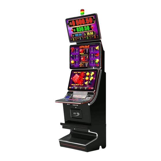
• The machine is made of high-quality materials and equipped with all necessary periphery devices and modules. • The main overview of the G 27-32 UP gaming machine is shown in the picture below: Page 6 www.egt.com... -
Page 7: Technical Specifications
G 27-32 UP Technical Specifications Name Value Manufacturer EURO GAMES TECHNOLOGY Ltd., Bulgaria Type EGT-VS23 Power Supply 100 - 240 V AC Voltage Current 4.0 - 1.7 A Consumption 360 W Frequency 50 - 60 Hz Fuses F1, F2 - T 10A / 250V~ - for the gaming machine;... -
Page 8: Operating Conditions
G 27-32 UP Dimensions Values Gross weight without a topper 175 kg Net weight without a topper 150 kg Gross weight of the topper 25 kg Net weight of the topper 22 kg Height with a topper 1 995,53 mm... -
Page 9: Safety And Precaution Measures
G 27-32 UP Transport box dimensions: Gaming machine 900 x 760 x 1 574 mm Topper (option) 925 x 830 x 275 mm Warning! After transporting or moving the machine from a colder to a warmer premise, please wait at least two hours before switching it on in order to avoid humidity condensation. - Page 10 G 27-32 UP Do not: • Operate the machine outdoors. • Operate the machine indoors with high humidity. • Install and use the machine where it can be exposed to water drops or sprinkles. • Operate close to heating units or expose to direct sunlight.
-
Page 11: Installation And Gaming Machine Service
Turn the main power switch on and wait for the appearance of a picture on the screen; • Teach the software in the iButton Reader to recognize EGT electronic keys (see EGT Electronic Keys_ iButton Reader Teaching_Service_Manual_EN_0x.pdf or contact the EGT Service);... -
Page 12: Doors Opening And Closing
G 27-32 UP Doors Opening and Closing Access to the main electronic components of the gaming machine located in its body is done by opening Main Door 1 and Bill Validator Door. The access is restricted by a locking system with a secret lock, which is controlled even when the power of the gaming machine is turned off. - Page 13 G 27-32 UP Main Door 1 Closing 1. Grab the Main Door 1 opened at the keyboard part and slide forward until full closing. Main Door 2 Opening and Closing Main door 2 Opening 1. Open the Main Door 1.
- Page 14 G 27-32 UP Main Door 2 Closing 1. Grab the detent with the left hand and move it to release the lock, grab the opened main door 2 with the right hand and pull it down. 2. Hold the main door 2 with both hands placed at the lower monitor and press it gently forward until the door is completely closed.
-
Page 15: Top Lamp (Signal Lights) Mounting
G 27-32 UP Safety Sheet Opening and Closing To gain access to the power supply units and power supply distributors, it is necessary to open the Safety Sheet. Safety Sheet Opening 1. Open the Bill Validator Door. 2. Open the Main Door 1. - Page 16 G 27-32 UP 3. The top lamp is connected to the corresponding electrical connector mounted on the back of the gaming machine (pos. 3). 4. The ground conductor is securely connected to the earth pin (4) via a DIN 6923 M4 nut.
-
Page 17: Control Keys
G 27-32 UP Control Keys By using the electro-mechanical key, you can access the credit forming screen, the service functions, the accounting of the machine, or the games. Electronic/Mechanical Key Purpose of Use By the ATTENDANT key, you can: •... - Page 18 G 27-32 UP Forming a Credit via an Attendant Key This procedure is for the service staff (attendant) in the casino, who uses a special key to insert credit. Warning! In countries where the legislation prohibits the addition of credits by the attendant, using his key, this option is disabled.
-
Page 19: Cashing Out The Player's Credit
G 27-32 UP Note: Make sure that the banknote used has a nominal and currency corresponding to those written on the sticker at the bill validator entrance. The type of banknotes that can be accepted is defined during the initial setup of the machine. -
Page 20: Machine Reservation And Release
G 27-32 UP 2. Press the SERVICE button, placed on the right, over the ticket printer exit, to call the attendant. The attendant gives the player the amount of credit in money, written on the splash, by hand (cash). Cashing Out via a Ticket Printer... -
Page 21: Top Lamp (Signal Lights)
G 27-32 UP Top Lamp (Signal Lights) • The Top Lamp is mounted on the top of the machine. • It consists of 3 signal lamps (lights) that are colored in three colors - red, yellow, and green. Note: For some markets the colors/number and their functions may differ from those described. -
Page 22: Component Maintenance
Clean only when the power is Connectors and may hinder its normal switched off! For prevention, you may Board Box operation. contact the nearest authorized EGT service center. Monitors/ Upon normal operation, a Minimum once a week, With a soft cloth and glass cleaning... - Page 23 G 27-32 UP Component Description Recommended Cleaning Maintenance Period Keyboard The system controls the Problem Solving: Panel condition of button LEDs The defective LED module is replaced by (if the test is enabled in a new one. Replace the LED module only...
-
Page 24: Hardware Components
G 27-32 UP Hardware Components General Description of Components View of the Cabinet with All Doors Closed Page 24 www.egt.com... - Page 25 G 27-32 UP Inside View of the Main Door 1 without Cover Inside View of the Main Door 2 Page 25 www.egt.com...
- Page 26 G 27-32 UP Inside View with the Main Door 2 Opened Inside View with the Bill Validator Door Opened Page 26 www.egt.com...
-
Page 27: Power Distributor Units (Pdu) And Power Supply Units (Psu)
G 27-32 UP Inside View with the Bill Validator Door and Safety Sheet Opened All the electronic components of the machine are located in the body, on Main door 1, Main door 2, and behind Bill Validator Door and Safety Sheet. The access is restricted by a locking system with a secret lock, which is controlled even when the power of the gaming machine is turned off. -
Page 28: Specialized Gaming Platform
G 27-32 UP Purpose of Use Kinds Purpose of Use It supplies input voltage to power supply units and additional General Power Distributor Module peripherals. It supplies input voltage to the gaming platform, the upper monitor, the lower monitor with a touchscreen, the cabinet fans, the RGB lights... -
Page 29: Monitors
G 27-32 UP • The BIOS memory and NVRAM backup batteries are located on the Exciter III gaming board. • There are 4 DIP switches and one of them (switch 1) is used for a machine memory reset. Exciter IV - Specialized Gaming Platform... -
Page 30: Ticket Printer (Option)
G 27-32 UP Ticket Printer (option) Purpose of Use The printer prints vouchers and tickets when credits are cashed out from the gaming machine. Note: For detailed information about ticket printer models supported by the machine, their technical Ticket Printer Models and Technical Parameters parameters, and so on, see the corresponding chapter in the Applications. -
Page 31: Meter Module
G 27-32 UP Technical parameters USB Keyboard Controller: Parameter Value Number of buttons controlled up to18 Number of LEDs controlled up to 18 Power +12V, 0.4A max Meter Module Type General Counters Module Purpose of Use • counts the impulses, transferred by the control platform to the appropriate mechanical meters;... -
Page 32: Decorative Lighting
G 27-32 UP Decorative Lighting Type Place in the gaming machine • the EGT logo; • White lighting at the Bill Validator entrance; • at the Ticket Printer exit. • around the upper monitor; • around the lower monitor; •... -
Page 33: Door Switches
G 27-32 UP Door Switches Type Push-Pull. Purpose of Use The switches detect openings and closings of all doors. Cabinet Identification Type Cabinet ID Purpose of Use It uniquely determines the type of gaming machine - number of monitors, type of monitors, resolution of monitors, and orientation of monitors - horizontal or vertical. -
Page 34: Gaming Machine Troubleshooting
The errors that occur are displayed on the machine screen in a form of a message. The error is cleared when its cause is solved. • Connect to the EGT service desk and report the information in the error message if you cannot solve the problem. Page 34... -
Page 35: Applications
G 27-32 UP Applications Bill Validator Models and Technical Parameters Type MEI SCN8347(E) Cashcode Type MFL JCM UBA-10-SS JCM iPro JCM iVizion NV 200 NV 200 Spectral iCT NBA JCM UBA PRO 500SS Note: The bill validators NV 200 and NV 200 Spectral are used only in a gaming machine with the Exciter IV platform. - Page 36 G 27-32 UP Technical Parameters MEI SCN 8347(E) Electrical Parameters Value Power Supply Voltage 12 ÷ 28 V DC ± 5% Standby 0.45 A Current consumption Operating mode 1.25÷3.0 A Communication Interface Environment Parameters Value Operation Temperature 0° C ÷ +60° C Operating Relative Humidity 5% ÷...
- Page 37 G 27-32 UP JCM UBA-10-SS / JCM iPro Electrical Parameters Value Power Supply Voltage 12V DC ± 5% Standby 0.3 A Current consumption Operating mode 1.6 A Communication Interface RS232 Environment Parameters Value Operation Temperature +5°C ÷ +50°C Operating Relative Humidity 30% ÷...
- Page 38 G 27-32 UP NV 200 Electrical Parameters Value Power Supply Voltage 12V DC ± 10% Standby 0.4 A Current consumption Operating mode 3A/ max 5 A Communication Interface RS232. USB 2.0 Environment Parameters Value Operation Temperature 0° C ÷ +50° C Operating Relative Humidity 30% ÷...
- Page 39 G 27-32 UP iCT NBA Electrical Parameters Value Power Supply Voltage 12V DC ± 10% to 24 V DC ± 10% Standby 0.35 A Current consumption Operating mode 1.25A Maximum 3.5 A Communication Interface RS232, USB 2.0 Environment Parameters Value Operation Temperature 0°...
- Page 40 G 27-32 UP Components Bill Validator Components Model MEI SCN8347(E) Cashcode MFL JCM UBA-10-SS Page 40 www.egt.com...
- Page 41 G 27-32 UP A Acceptor Unit Front Panel Bezel JPL Connector JCM iPro Front Upper Guide Access Lever JCM iVision M Transport Unit Release Lever (Acceptor Unit) Bezel (Option) - use from JCM iPro N Power ON LED (Green) model!
- Page 42 G 27-32 UP Bill Validator Components Model NV 200 NV 200 Spectral Collecting Bills Collecting bills from CashCode MFL - 1 - - 2 - - 3 - 1. Open the bill validator door. 2. Push the lever, pointed by the small arrow in picture 1 above, and pull the cassette out.
- Page 43 G 27-32 UP 4. Take the bills, as shown in picture 3 above. 5. Lock the cassette and put it back into the housing. Collecting bills from JCM UBA-10-SS 1. Open the bill validator door. 2. Hold the cassette handle and pull it in the direction, pointed by the arrow in picture 1 above.
- Page 44 G 27-32 UP Removing bills from JCM UBA-10-SS Depending on the situation encountered jammed bills must be removed as shown in the picture above. Configuring the Bill Validator Configuring CashCode MFL CashCode MFL configuration is done by setting switches, located at the rear end of the validating head, under a transparent plastic cover.
- Page 45 G 27-32 UP CashCode MFL operates in two basic modes: validation and service. Defining settings, operating mode, and enabled denominations are performed by two groups of switches - SW1 and SW2. The function of the group of SW1 DIP switches is the following: Switch SW 1.1...
- Page 46 G 27-32 UP Configuring JCM UBA-10-SS JCM UBA-10-SS operates in two modes: test and normal. Defining settings, operating mode, and enabled denominations is performed by setting switches. Switch Accept of barcode vouchers disabled Accept of barcode vouchers enabled Denomination 1 disabled...
-
Page 47: Ticket Printers Models And Technical Parameters
G 27-32 UP Ticket Printers Models and Technical Parameters Type JCM GEN 5 Ithaca Epic 950 Technical parameters JCM GEN 5 Electrical Parameters Value Power Supply Voltage: 24 V DC ± 5% Current consumption At 24 V and 25% black max 2.7 A... - Page 48 G 27-32 UP Ithaca Epic 950 Electrical Parameters Value Power Supply Voltage: 24 V DC ± 10% Current consumption At 24 V and 25% black max 2.2 A Communication Interface RS 232 Environment Parameters Value Operation Temperature +5°C ÷ +45°C Storage Temperature -10°C ÷...
- Page 49 G 27-32 UP Loading tickets in Ithaca Epic 950 ticket printer 1. Load tickets into the ticket supply tray, making sure that the black dot is positioned as shown in the picture 1 above. 2. Insert the leading ticket into the printer mechanism’s insertion guide area – picture 2 above. The ticket should be fed about a ½"...
-
Page 50: Modular Diagrams Of Components
G 27-32 UP Modular Diagrams of Components Exciter III Page 50 www.egt.com... - Page 51 G 27-32 UP Exciter IV Page 51 www.egt.com...
- Page 52 G 27-32 UP Power Page 52 www.egt.com...
- Page 53 G 27-32 UP Control Page 53 www.egt.com...
- Page 54 G 27-32 UP RGB Lights Page 54 www.egt.com...
- Page 55 G 27-32 UP Optional Peripherals Note: The bill validators NV 200 and NV 200 Spectral are used only in a gaming machine with the Exciter IV platform. Page 55 www.egt.com...
- Page 56 G 27-32 UP Keyboard Page 56 www.egt.com...
- Page 57 G 27-32 UP Monitor and Touchscreen of the Dynamic Touch Keyboard Page 57 www.egt.com...
- Page 58 G 27-32 UP 32” EGT Upper Monitor Page 58 www.egt.com...
- Page 59 G 27-32 UP 27” EGT Lower Monitor with a Touchscreen Page 59 www.egt.com...
-
Page 60: Connectors Of Backplane Board
G 27-32 UP Connectors of Backplane Board BH40S 2x20 pin male PIN No Signal Name PIN No Signal Name T_RXD4 T_TXD4 T_RXD7 T_TXD7 T_RXD5 T_TXD5 T_RXD6 T_TXD6 T_RXD2 T_TXD2 T_RXD3 T_TXD3 DIN0 DIN1 DIN2 DIN3 DIN4 DIN5 DIN6 DIN7 DIN8... - Page 61 G 27-32 UP INTRUSION SWITCHES MOLEX 7x2pin Mini-fit Straight PIN No Signal Name PIN No Signal Name INTRUSION0 INTRUSION1 INTRUSION2 INTRUSION3 INTRUSION4 INTRUSION5 INTRUSION6 Serial Ticket Printer MOLEX 3x2pin Mini-fit Straight PIN No Signal Name PIN No Signal Name R_RXD7...
- Page 62 G 27-32 UP Casino Net 1 MOLEX 2x2pin Mini-fit Straight PIN No Signal Name/Current PIN No Signal Name/Current R_RXD2 R_TXD2 +12V / 1.5A Casino Net 2 MOLEX 2x2pin Mini-fit Straight PIN No Signal Name/Current PIN No Signal Name/Current R_RXD3 R_TXD3 +12V / 1.5A...
- Page 63 G 27-32 UP HDD POWER OUTPUT AMP 350211 PIN No Signal Name/Current PIN No Signal Name/Current +12V / 1.5A UPS POWER V1.6 MOLEX 2x2pin Mini-fit Straight PIN No Signal Name/Current PIN No Signal Name/Current BU+12V BU+12V UPS POWER V2.2 MOLEX 3x2pin Mini-fit Straight...
-
Page 64: Contacts
Address 6 Panorama Sofia Str., Sofia Park RichHill Business Center, Block A 1756 Sofia, BULGARIA EGT Technical Support - Head Office Phone: +359 2 890 24 68 Fax: +359 2 890 24 88 Mobile: +359 896 71 02 72 e-mail: service@egt-bg.com;...
Need help?
Do you have a question about the G 27-32 UP and is the answer not in the manual?
Questions and answers