Advertisement
Quick Links
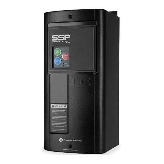
Operation
• Intended for use with 3-Phase, 50/60Hz
• Accepts 208-600VAC +10%
• Short Circuit (RMS, Symmetrical)
Stand-Alone Overload Unit - 200 KAIC, 600V Max.
Standard Starter - See UL label on panel
Combination Starter - See UL label on panel
• Ambient Operating Temperature = -20°C to 60°C
• Ambient Storage Temperature = -40°C to 85°C
DANGER
• Ensure that all connections are properly torqued and enclosure is closed
prior to applying power to the device.
• Ensure all mechanical equipment operated by the starter is clear for safe
operation in case of starter activation.
• When in AUTO mode, starter may be activated remotely by the
control system
Operation Modes
HAND
Place the switch in the HAND position to manually engage motor.
OFF (RESET)
Place the switch in the OFF position to manually disengage the
motor. Additionally, the OFF position serves as a manual reset.
Place the switch in the OFF position for 5 seconds to reset the
starter after a fault trip.
AUTO
Placing the switch in the AUTO position will allow the starter to be
controlled by a remote Start/Stop command.
Setting Adjustments
Overload
Set the overload dial to the SFA amperage value listed on the
motor nameplate. If no amperage value for SFA is provided, set the
overload dial to the FLA listed on the motor nameplate.
Underload
For submersible motor applications, it is suggested that the dial be
set to 70% to protect against dry-run condition.
I/O Descriptions
TERMINAL
DESCRIPTION
BLOCK
Dry Auto Input - When closed, the starter will run when in
D1 / D2
Auto Mode. (N.O. dry contact or transistorized input)
Fault Relay Output - Normally open relay contacts that
O1 / O2
closes in the event of a fault condition.
120VAC, 0.6A
For the above: Use 12-20AWG wire for I/O terminal blocks
TERMINAL
DESCRIPTION
Run-Timer Input - Connections for optional 1/2-12hr run
T- / TI / T+
timer.
Pilot Device Input - Connections for a 3-position (HOA)
D3 / D4 / D5
switch for motor control.
(Wired from manufacturer on N3R enclosed units)
Contactor Output - Provides a 24V output to close the
contactor when the motor starter is commanded in either
HAND or AUTO mode. Once the contactor is closed, the
C- / C+
output drops to 2-4V to maintain contactor closure while
optimizing efficiency. Only for use with Franklin Electric
contactor with 24VAC coil (24V, 0.875A Max).
For the above: Use 14-26AWG wire for I/O terminals, torque to 3.5 lb-in
WARNING
OVERLOAD/CONTROL UNIT MUST BE REPLACED IF BURNOUT OF THE
EXTERNAL CURRENT TRANSFORMERS OCCURS.
SSP I2t Trip Curve
1000
100
10
1
1
2
3
4
5
6
% of Overload Amperage Setting x100
Product improvement is a continual process. Cerus, Mira, Smartstart and
associated logos are trademarks of Franklin Electric Co., Inc.
All sales are subject to FE Terms & Conditions.
800.348.2420 | www.franklinwater.com
Installation & Operation Guide
This manual is available for download at
www.franklinwater.com
Precautions
To prevent injury and property damage, follow these instructions.
Failure to adhere to installation/operation procedures and all
applicable codes may result in hazards as indicated by warning
codes outlined below:
DANGER
indicates an imminently hazardous situation which, if not avoided, will
result in death or serious injury. This signal word is to be limited to the
most extreme situations.
WARNING
indicates a potentially hazardous situation which, if not avoided, could
result in death or serious injury.
CAUTION
indicates a potentially hazardous situation which, if not avoided, may
result in minor or moderate injury. It may also be used to alert against
unsafe practices.
This is the safety alert symbol. Read and follow instructions carefully to
avoid a dangerous situation.
This symbol alerts the user to the presence of "dangerous voltage"
inside the product that might cause harm or electrical shock.
Safety Instructions
DANGER
Equipment can start automatically. Lockout/tagout before servicing.
7
8
9
10
CAUTION
As with all electrical products, read manual thoroughly. Only qualified,
expert personnel should perform maintenance and installation. Contact the
nearest authorized service facility for examination, repair, or adjustment.
Do not disassemble or repair unit unless described in this manual; death
or injury to electrical shock or fire hazard may result. Specifications and
manual data subject to change. Consult factory for additional information.
QSTART-SSP/S4-V1
Advertisement

Related Manuals for Franklin Electric SmartStart SSP Series


Summary of Contents for Franklin Electric SmartStart SSP Series
- Page 1 Product improvement is a continual process. Cerus, Mira, Smartstart and expert personnel should perform maintenance and installation. Contact the associated logos are trademarks of Franklin Electric Co., Inc. nearest authorized service facility for examination, repair, or adjustment. All sales are subject to FE Terms & Conditions.
- Page 2 Program Switches Electronic Overload Operation Installation When an fault trip occurs, the fault LED will illuminate. The type of fault will Position be indicated by flashing a combination of the HAND/OFF/AUTO/RUN/FAULT DANGER LEDs as indicated in the table below. HAZARDOUS VOLTAGE •...
Need help?
Do you have a question about the SmartStart SSP Series and is the answer not in the manual?
Questions and answers