Franklin Electric SubDrive75 Installation Manual
Constant pressure controller
Hide thumbs
Also See for SubDrive75:
- Quick installation manual (35 pages) ,
- Installation manual (48 pages)

Related Manuals for Franklin Electric SubDrive75


Summary of Contents for Franklin Electric SubDrive75
- Page 1 SubDrive75/100/150 Constant Pressure Controller Installation Manual 05.2010 Doc Nb.: 308 018 602; Rev.: 0...
-
Page 2: Table Of Contents
SubDrive75 ........ -
Page 3: Declaration Of Conformity
Declaration of Conformity Franklin Electric declares under our sole responsibility, all SubDrive/MonoDrive series 587 020 3xx0 controllers are in conformity with the Council Directives on the approximation to the laws of the EEC member states relating to the following: Electromagnetic Compatibility 2004/108/EC: Adjustable Speed Electrical Power Drive... -
Page 4: About This Document
Technical changes may be made without notice in the interest of product development. Loss of guarantee and liability exclusion: Franklin Electric shall not be liable for the damage resulting from any non-intended use. The risk of such use rests solely with the user. -
Page 5: Model Parameters
Make sure that no danger zones are accessible (e.g. electrical connections). • Read the pump manufacturer‘s commissioning instructions before switching on any control gear. • Repairs must only be carried out by authorized professional workshops. Use only original Franklin Electric spare parts. Storage, transport and disposal Storage •... -
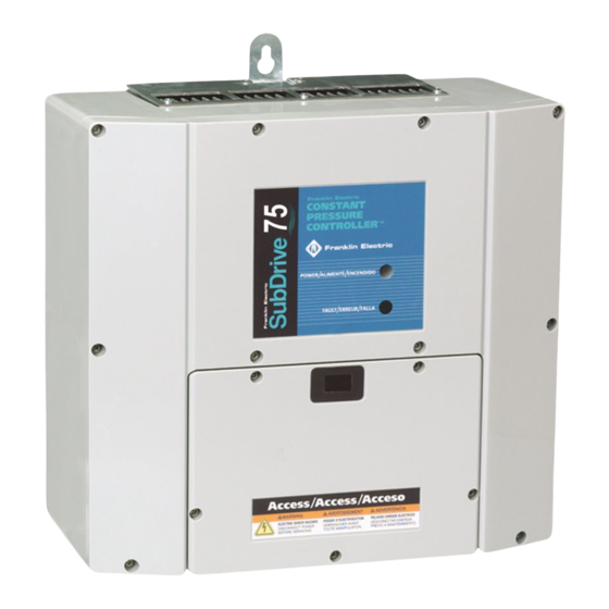
Page 6: Description And Features
Description and Features The Franklin Electric SubDrive is a dependable residential water system controller that uses advanced electronics to enhance the performance of standard submersible pumps. When used with the specified Franklin Electric motor (see Table 1, pg. 3), the SubDrive eliminates pressure cycling associated with conventional water well systems and owners of private water well systems can enjoy “city-like”... -
Page 7: How It Works
How it Works The Franklin Electric SubDrive is designed to be part of a system that consists of only four components: A. Standard Pump and Franklin Electric Motor B. SubDrive Controller C. Small Pressure Tank (see Table 4, pg. 14) D. -
Page 8: Subdrive75
Pump Sizing – SubDrive75 The SubDrive75 is configured at the factory for use with 0.55 kW pumps that are mounted to 1.1 kW Franklin Electric three-phase motors. In general, the SubDrive75 will enhance the performance of a 0.55 kw pump to a similar or better performance than a conventional 1.1 kW pump of the same flow rating (pump series). -
Page 9: Subdrive100
The SubDrive100 is configured at the factory for use with 0.75 kW pumps that are mounted to 1.5 kW Franklin Electric three-phase motors. In general, the SubDrive100 will enhance the performance of a 0.75 kW pump to a similar or better performance than a conventional 1.5 kW pump of the same flow rating (pump series). -
Page 10: Subdrive150
The SubDrive150 is configured at the factory for use with 1.1 kW pumps that are mounted to 2.2 kW Franklin Electric three-phase motors. In general, the SubDrive150 will enhance the performance of a 1.1 kW pump to a similar or better performance than a conventional 2.2 kW pump of the same flow rating (pump series). -
Page 11: Underload Sensitivity For Deep Wells
Underload Sensitivity Selection – SubDrive75/100/150 The SubDrive controller is configured at the factory to ensure detection of Underload faults in a wide variety of pumping Configuration applications. In rare cases (as with certain pumps in shallow Switch SW1 wells) this trip level may result in nuisance faults. If the pump is installed in a shallow well, activate the controller and observe system behavior. -
Page 12: Underload Smart Reset
INFO Use SubDrive only with Franklin Electric 4-inch submersible motors as specified in this manual. Use of this unit with any other Franklin Electric motor or with motors from other manufacturers may result in damage to both motor and electronics. -
Page 13: Controller Location Selection
Controller Location Selection The SubDrive controller is intended for operation in ambient temperatures up to 50 °C at 230 VAC input. The following recommendations will help in selection of the proper location of the SubDrive unit: 1. A tank tee is recommended for mounting the tank, pressure sensor, pressure gauge, and pressure relief valve at one junction. -
Page 14: Circuit Breaker And Wire Sizing
Below recommendations are identical to ones found in motor literature for off the grid operation at 230V / 50Hz, cable length being limited to max. 330m. Metric Cable Size, Square Millimeters, Copper Rated Power Franklin Electric Wire, 70°C Rated Insulation Controller Model Motor Model... -
Page 15: Quick Reference Guide
Technical changes without notice / Techn. Änderungen vorbehalten / Modifications techniques réservées sans préavis / 5930... -
Page 16: Pressure Tank
The SubDrive can also use an existing tank with a much larger capacity. Table 4: Minimum Pressure Tank Size (Total Capacity) Pump Flow Rating Controller Model Minimum Tank Size SubDrive75 8 liters Less than 2,5 m³/h SubDrive100 18 liters SubDrive150... -
Page 17: Wiring Connections
Wiring Connections DANGER Serious or fatal electrical shock may result from failure to connect the motor, the SubDrive, metal plumbing and all other metal near the motor, or cable to the power supply ground terminal, using wire no smaller than motor cable wires. -
Page 18: Start-Up And Operation
10. Connect the other end of the pressure sensor cable with the Remove Rubber End Cap To Adjust Pressure With 7/32" Allen Wrench (provided) two spade terminals to the pressure sensor. The connections are interchangeable (Figure 5A). Pressure Sensor 11. Set the pressure tank pre-charge at 70% of the desired water Boot pressure setting. -
Page 19: Specifications Subdrive 75
Specifications – SubDrive75 Voltage 190-260 VAC Frequency 60/50 Hz Input from Current (max) 11 Amps (RMS) Power Source Power Factor 1.0 (constant) (single-phase) Power (idle) 35 Watts Power (max) 2400 Watts Voltage Adjusts with Frequency 0.55 kW pump 30 - Hz... -
Page 20: Subdrive 150
A. Operating temperature is specified at full output power when installed as described in Controller Location Selection on pg. 11. B. Refer to pg. 18 for detailed Mounting Dimensions. C. If a pump other than the default rating is used, refer to pg. 8 for Drive Configuration. Mounting Dimensions SubDrive75/100/150: 13.4 29.2 24.8 32.5 35.6... -
Page 21: Accessories
Surge Capacitor – capacitor used on the service panel to help eliminate power interference: 225 199 901 (SubDrive75/100/150) SubDrive75 N1 Fan Kit – replacement fan for SubDrive75 with 80 mm (3.15 in) fan: 225 635 SubDrive75 N1 Fan Kit – replacement fan for SubDrive75 with 92 mm (3.62 in) fan: 225 635 SubDrive100/150 N1 Fan Kit –... -
Page 22: Notes
Notes Technical changes without notice / Techn. Änderungen vorbehalten / Modifications techniques réservées sans préavis / 5930...
Need help?
Do you have a question about the SubDrive75 and is the answer not in the manual?
Questions and answers