Table of Contents
Advertisement
Available languages
Available languages
OWNER'S MANUAL
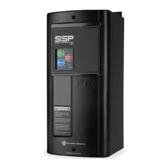
BAS Building Automation Starter
The BAS Building Automation Starter (with SmartStart
integration with automation systems. It is equipped with advanced I/O includ-
ing Fireman's Override and damper control. With a 200 to 600 V input and 1-
40 A adjustable overload, the BAS is the right starter for almost any job.
3-Phase, 50/60 Hz, 200~600 VAC, NEMA/UL Type 1, 3R, 4X, and 12 Enclosed
Starter
• Ambient Operating Temperature: 41 °F (5 °C) to 104 °F (40 °C)
• Ambient Storage Temperature: -40 °F (-40 °C) to 185 °F (85 °C)
For additional important safety, operation, and warranty information refer to
the product page and AIM Manual available at: www.franklinwater.com.
SAFETY INSTRUCTIONS
This equipment should be installed and serviced by technically qualified personnel who are familiar with
the correct selection and use of appropriate tools, equipment, and procedures. Failure to comply with
national and local electrical and plumbing codes and within Franklin Electric recommendations may result
in electrical shock or fire hazard, unsatisfactory performance, or equipment failure.
Know the product's application, limitations, and potential hazards. Read and follow instructions carefully to
avoid injury and property damage. Do not disassemble or repair unit unless described in this manual.
Failure to follow installation or operation procedures and all applicable codes may result in the following
hazards:
High voltages capable of causing severe injury or death by electrical
shock are present in this unit.
•
To reduce risk of electrical shock, disconnect power before working on or around the system. More than one disconnect switch
may be required to de-energize the equipment before servicing.
•
Make sure the ground terminal is connected to the motor, control enclosures, metal plumbing, and other metal near the motor or
cable using wire no smaller than motor cable wires.
•
To maintain overcurrent and short-circuit protection, the manufacturer's instructions for selecting current elements and setting
the inverse trip time circuit breaker must be followed.
•
Tripping of the inverse trip time circuit breaker is an indication that a fault current has been interrupted. Current-carrying compo-
nents of the magnetic motor controller should be examined and replaced if damaged to reduce the risk of fire or electric shock.
•
Do not locate starter in an environment subject to flammable gases, dusts, or materials. Contact arcing can induce explosion or
fire.
•
All electrical connections must be made by a qualified electrical technician.
•
Check local electrical and building codes before installation. The installation must be in accordance with their regulations as well
as the most recent National Electrical Code (NEC), Occupational Safety and Health Act (OSHA), and Canadian Electrical Code
(CEC).
TM
) is designed for easy
EN
English
Advertisement
Table of Contents

Related Manuals for Franklin Electric BAS 9-P-40 Series


Summary of Contents for Franklin Electric BAS 9-P-40 Series
- Page 1 Failure to comply with national and local electrical and plumbing codes and within Franklin Electric recommendations may result in electrical shock or fire hazard, unsatisfactory performance, or equipment failure.
-
Page 2: Physical Installation
INSTALLATION Physical Installation Risk of bodily injury, electric shock, or equipment damage. • This equipment must not be used by children or persons with reduced physical, sensory or mental abilities, or lacking in experi- ence and expertise, unless supervised or instructed. Children may not use the equipment, nor may they play with the unit or in the immediate vicinity. -
Page 3: Power Wiring Connections
INSTALLATION Electrical Installation Power Wiring Connections NOTE: Consult the product wiring diagram located on the starter enclo- sure for customized panels. • Wire main power input and motor leads to the appropriate terminals, tightened as indicated in the “Specifications” on page •... - Page 4 9. C-/C+ Contactor Output: Provides a 24 V output to the contactor when the motor starter is in either Hand or Auto mode and the damper switch input is closed. Only for use with Franklin Electric contactors with 24 VAC coil (0.42 A max.)
-
Page 5: Starter Configuration
STARTER CONFIGURATION Electrical Installation Relay Output Current Ratings NOTE: This table applies to the O1, O, and O2 terminals. Voltage Amps 110 VDC 125 VDC 30 VDC 120 VAC 125 VAC 50/60 240 VAC 0.25 STARTER CONFIGURATION SmartStart Disable (DIP SW1) Default = OFF OFF ON Place in the ON (Right) position to disable the... -
Page 6: Operation
HAND & AUTO decreasing). Disabled during startup For technical assistance, parts, or repair, please contact: 800.701.7894 | franklinwater.com Franklin Electric Co., Inc. | Oklahoma City, OK 73157-2010 10000012648 Rev. 000 11/22 Copyright © 2022, Franklin Electric, Co., Inc. All rights reserved. -
Page 7: Manual Del Propietario
No cumplir con los códigos eléctricos y de fontanería nacionales y locales y con las recomendacio- nes de Franklin Electric puede provocar peligro de choque eléctrico o incendio, desempeño no satisfactorio o fallo del equipo. -
Page 8: Instalación Física
INSTALACIÓN Instalación física Riesgo de lesiones, choque eléctrico o daños al equipo. • Este equipo no deben usarlo niños ni personas con capacidades físicas, sensoriales o mentales reducidas, ni aquellos que carez- can de experiencia y capacitación, salvo que estén bajo supervisión o instrucción. Los niños no podrán usar el equipo ni jugar con la unidad o en las cercanías inmediatas. -
Page 9: Conexiones Eléctricas
INSTALACIÓN Conexiones eléctricas Conexiones eléctricas Especificaciones Torque Calibre del Número de pieza cable (AWG) Entrada (pulgadas-libras) Salida (pulgadas-libras) BASxx-9-P-40 8-14 BASxx-18-P-40 BASxx-32-P-40 8-12 BASxx-40-P-40 BASxx-9-P-Gxx-40 10-14 BASxx-18-P-Gxx-40 BASxx-32-P-Gxx-40 8-12 BASxx-40-P-Gxx-40 Conexiones del cableado de alimentación NOTA: Consulte el diagrama de cableado del producto ubicado en el gabinete del arrancador para paneles personalizados. - Page 10 INSTALACIÓN Conexiones eléctricas Conexiones de cableado de E/S NOTA: Utilice un cable de 26~14 Ejecución AWG y apriete a 3,5 lb-in para el 12-250 VAC/DC Entrada automática cableado de control. entradas de voltaje Anulación 1. Entrada automática de voltaje 12-250 VAC/DC Entrada de bomberos V3/V4: Utilice esta entrada para Estado...
- Page 11 CONFIGURACIÓN DEL ARRANCADOR Conexiones eléctricas Capacidades nominales de corriente de salida del relé NOTA: Esta tabla se aplica a los terminales O1, O y O2. Voltaje Amperios 110 VDC 125 VDC 30 VDC 120 VAC 125 VAC 50/60 240 VAC 0.25 CONFIGURACIÓN DEL ARRANCADOR Desactivar SmartStart...
- Page 12 FUNCIONAMIENTO Conexiones eléctricas Modos de fallo de alimentación (DIP SW4 y 5) Interruptor Modos de fallo de alimentación Modo por defecto: Vuelve siempre al último modo sin retardo en caso de falla de alimentación. Vuelve al último modo con un retardo de 10 segundos en caso de falla de ali- mentación.
- Page 13 FUNCIONAMIENTO Fallas de diagnóstico del sistema Fallas de diagnóstico del sistema Falla LED intermitente Descripción Se activa cuando el arrancador supera el intervalo de Falla de ciclo “NONE” (NINGUNA) 20 arranques por minuto. Fallo de “RUN” y “FAULT” Un componente tiene un problema. Póngase en con- hardware (EJECUTAR y FALLA) tacto con Atención al Cliente.
- Page 14 Para la ayuda técnica, por favor póngase en contacto: 800.701.7894 | franklinagua.com Franklin Electric Co., Inc. | Oklahoma City, OK 73157-2010 10000012648 Rev. 000 11/22 Copyright © 2022, Franklin Electric, Co., Inc. Todos los derechos están reservados.
-
Page 15: Manuel Du Propriétaire
équipement. Le non-respect des réglementations nationales et locales en matière d’installations électriques et de plomberie et des recom- mandations de Franklin Electric peut entraîner des risques de décharge électrique ou d’incendie, des per- formances insatisfaisantes ou une défaillance de l’équipement. -
Page 16: Installation Physique
INSTALLATION Installation physique Risque de blessure, de choc électrique ou de dégâts matériels. • Cet équipement ne doit pas être utilisé par des enfants ou des personnes aux capacités physiques, sensorielles ou cognitives réduites, ou par des personnes n’ayant pas l’expérience ou l’expertise appropriée, sauf si ces personnes sont supervisées ou ont reçu des instructions à... -
Page 17: Raccordements Électriques
INSTALLATION Raccordements électriques Raccordements électriques Spécifications Couple Calibre de fil Numéro de commande (AWG) Entrée (Nm [po-lb]) Sortie (Nm [po-lb]) BASxx-9-P-40 8-14 BASxx-18-P-40 BASxx-32-P-40 8-12 BASxx-40-P-40 BASxx-9-P-Gxx-40 10-14 BASxx-18-P-Gxx-40 BASxx-32-P-Gxx-40 8-12 BASxx-40-P-Gxx-40 Connexions du câblage d’alimentation REMARQUE : Consultez le schéma de câblage du produit situé... - Page 18 9. Sortie contacteur C-/C+ : Fournit une sortie de 24 V au contacteur lorsque le démarreur du moteur est en mode Manuel ou Auto et lorsque l’entrée du commutateur du clapet est fermée. Accepte pour le contacteur Franklin Electric avec bobine de 24 V AC.
- Page 19 CONFIGURATION DE DÉMARRAGE Raccordements électriques Courants nominaux des sorties relais REMARQUE : Ce tableau s’applique aux bornes O1, O et O2. Tension Ampères 110 VDC 125 VDC 30 VDC 120 VAC 125 VAC 50/60 240 VAC 0.25 CONFIGURATION DE DÉMARRAGE Désactivation de SmartStart (DIP SW1) Par défaut = OFF (ARRÊT)
- Page 20 FONCTIONNEMENT Raccordements électriques Modes de panne d’alimentation (DIP SW4 et 5) Commutateur Modes de panne d’alimentation Mode par défaut : Retourne toujours au dernier mode sans délai en cas de panne d’alimentation. Retourne au dernier mode dans un délai de 10 secondes en cas de panne d’alimentation. En cas de panne d’alimentation, retournez au mode arrêt.
- Page 21 FONCTIONNEMENT Défauts de diagnostic du système Défauts de diagnostic du système Erreur DEL clignotante Description S’active lorsque le démarreur dépasse le taux de 20 démar- Erreur de cycle « NONE » (AUCUN) rages par minute. Défaut « RUN » et « FAULT » (EXÉCUTER et ERREUR) Un composant a un problème.
- Page 22 REMARQUES...
- Page 23 REMARQUES...
- Page 24 Pour l’aide technique, entrez s’il vous plaît en contact : 800.701.7894 | franklinwater.com Franklin Electric Co., Inc. | Oklahoma City, OK 73157-2010 10000012648 Rév. 000 11/22 Droits d’auteur © 2022, Franklin Electric, Co., Inc. Tous droits réservés.
Need help?
Do you have a question about the BAS 9-P-40 Series and is the answer not in the manual?
Questions and answers