Table of Contents
Advertisement
Quick Links
Model 310 & Model 300
USER'S MANUAL
These instructions contain important information for safe use of the product. Read
1
the entire contents of these Instructions For Use, including Warnings and Cautions,
before using the paraPAC plus. Failure to properly follow warnings, cautions and
instructions could result in death or serious injury to the patient.
© 2012 Smiths Medical family of companies. All rights reserved.
PN 504-2117
Issue: 7 2012 / 10
paraPAC plus
Ventilator
Smiths Medical International Ltd.
Bramingham Business Park, Enterprise Way
Luton, Bedfordshire, LU3 4BU, UK
Tel: +44 (0)1233 722100
H
Manufacturer
www.smiths-medical.com
2
Advertisement
Table of Contents

Related Manuals for Smiths Medical Pneupac paraPAC plus


Summary of Contents for Smiths Medical Pneupac paraPAC plus
- Page 1 Manufacturer Smiths Medical International Ltd. Bramingham Business Park, Enterprise Way Luton, Bedfordshire, LU3 4BU, UK Tel: +44 (0)1233 722100 © 2012 Smiths Medical family of companies. All rights reserved. PN 504-2117 Issue: 7 2012 / 10 www.smiths-medical.com...
- Page 2 1265 Grey Fox Road St Paul, MN 55112 USA Tel: 1 800 258 5361 (US/CA) Tel: +1 614 210 7300 Australian Representative: Smiths Medical Australasia Pty. Ltd. 61 Brandl Street, Eight Mile Plains Brisbane, QLD 4113, Australia Tel: +61 (0)7 3340 1300...
-
Page 3: Table Of Contents
paraPAC plus Ventilator User's Manual Model 310 & Model 300 Table of Contents SECTION: 1 SAFETY INSTRUCTIONS ..........7 (a) Summary Statement ..................7 (b) Warnings, Cautions and Precautions ............8 WARNINGS ....................8 (ii) CAUTIONS .................... - Page 4 Therapy (Model 310 only) ..............45 (g) Ventilating Intubated Patients..............45 (h) Positive End Expiration Pressure (PEEP) ..........46 (i) PEEP on Model 300 (Patient Circuit Part No. 100/905/341)......46 (j) Use in Contaminated Atmospheres............46 (k) ...
- Page 5 Figure 11: Charts Illustrating the Effects Of Inflation Pressure On Delivered Tidal Volume & Oxygen Concentration ............90 Smiths Medical International Ltd. reserves the right to make changes, without notice, which may affect the information contained in this manual.
- Page 6 Page Intentionally Blank 504-2117 Issue 7 2012 / 10...
-
Page 7: Safety Instructions
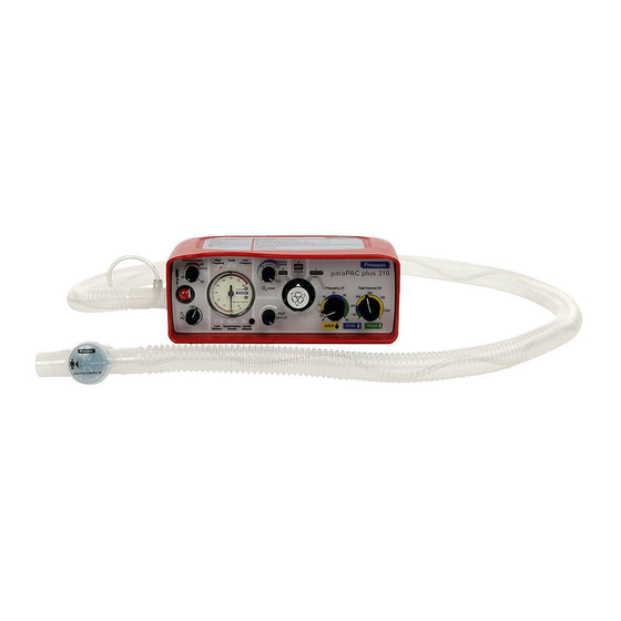
SECTION: 1 SAFETY INSTRUCTIONS Summary Statement The paraPAC plus ventilators are portable devices intended for the ventilation of adults, children and infants (above 10kg) during transportation and emergency situations. They consist of a control module and a remote patient valve, connected by means of a breathing hose. Both pneumatic and electronic alarms are incorporated. -
Page 8: (B) Warnings, Cautions And Precautions
The paraPAC plus ventilator is intended only for use in transport and emergency situations where the patient is being constantly monitored by the carer. The integrated alarm unit is intended to alert the carer to changes in the patient’s ventilation but it cannot ensure that the patient’s blood gases are maintained at the required level. - Page 9 Use of the ventilator and Patient breathing Circuit at Tidal Volumes below 150ml may result in a CO build up and inadequate ventilation of the patient. For tidal volumes below 150ml the Smiths Medical Hyperinflation Bag system, in conjunction with the CPAP / O L/min connector on the ventilator may be used.
- Page 10 15. Warning: Functional Check (Sect. 3(b)13) Deviations noted at functional check should be reported immediately to Smiths Medical and the unit must be taken out of service to avoid the risk of death or serious injury. 16. Warning: Release of Cylinder Pressure (Sect. 3(b)13) To avoid ignition by adiabatic compression, connect the ventilator to the regulator before opening the cylinder valve slowly.
- Page 11 19. Warning: Interpreting of ‘Spontaneous Breath’ Indicator (Sect. 4d) Actuation of the ‘Spontaneous Breath’ indicator only indicates that spontaneous breathing has been detected and that the low-pressure alarm has been reset as a consequence. The operator must still ensure that patient minute ventilation is adequate. 20.
- Page 12 Where fitting in a confined space is necessary, consult Smiths Medical for installation advice. 31. Warning: Storage in Low Temperatures (Appendix B) After storing at temperatures below -18°C set controls to 40 bpm and...
-
Page 13: (Ii) Cautions
Warnings specific for the Patient Breathing Circuit Note: The warnings specific for the Patient Breathing Circuit are listed here for information only. Refer to Instructions for Use part number 100/905/340 and 100/905/341 for the latest information. A. Users must ensure that they are knowledgeable and proficient in the use of the ventilator and circuit before use to allow them to be used safely. - Page 14 4. Caution: Do not attempt to sterilise the paraPAC plus or to clean it by immersion in any fluid. Do not use any cream cleanser. Do not allow any petrochemical or its derivative (petrol, diesel, paraffin etc.) come into contact with the device. Do not autoclave the paraPAC plus.
-
Page 15: General Information
Variants Covered by this Manual SECTION: 2 GENERAL INFORMATION This manual addresses both the paraPAC plus variants – model 310 and 300. Intended Use Features that are not applicable to the model 300 are annotated (Model 310 Warning: To avoid the risk of ignition, do not smoke or have naked flames in Only), as model 310 is enhanced variant of the model 300. -
Page 16: (B) General Description
General Description The paraPAC plus ventilator consists of a control module and a remote patient valve, connected by means of a corrugated hose (See Fig 1). A description of controls and features on the paraPAC plus ventilator is given in Section 2 (d), the number reference against each description corresponds to the number shown in Figure 2. -
Page 17: (C) Contraindications - None Known
When O is selected, only the internal demand valve is DEMAND, energised by the gas supply. When the patient is connected to the patient valve, any spontaneous breathing effort is satisfied by flow from the demand valve. This provides a very gas efficient method of treating a victim with an unprotected airway where enhanced oxygen [tidal volume dependent see table in Appendix C] is recommended as the approved therapy. -
Page 18: Figure 2.2: Controls, Features & Interfaces Of The Parapac Plus 300
Tidal Volume Control (T This rotary control knob gives continuous adjustment of the flow to the patient over the range 8 & 39 litres per minute. For ease of use in the emergency situation, it is calibrated in terms of tidal volume (V x Flow). - Page 19 Function Switch & Manual Push-button This knob operates a rotary switch to select O DEMAND or II FLOW (this function is only available on Model 310 only, see items 19 and 20 below for details of this function) or I VENTILATE CMV which provides Fig.
- Page 20 Relief Pressure Control This rotary control knob gives continuous adjustment of the maximum proximal pressure Fig. 2e: Relief Pressure by setting the relief valve spring loading. Control When the proximal pressure reaches this setting, any additional gas is allowed to escape to atmosphere via the relief valve.
- Page 21 Pressure Monitor This pressure manometer displays the proximal pressure, as measured at the patient valve connection port. It will give an indication of the Fig. 2g: Inflation actual proximal pressure under all normal Pressure Monitor (O2 %) settings of the ventilator. Warning: Ventilators must never be used without the sensing line attached as this will result in a loss of ‘delivered volume’...
- Page 22 High Inflation Pressure Alarm An audible alarm is provided to signal that the Fig. 2j: High Inflation Pressure Indicator / Alarm relief pressure has been achieved and that gas loss is occurring through the relief valve. The alarm is pneumatically operated by means of gas vented through the relief valve.
- Page 23 11. Low Inflation Pressure (Disconnect) Alarm A medium priority* audible and visual alarm will operate to warn the user of a possible Fig. 2l: Low Pressure disconnection in the ventilator breathing system Indicator or that the ventilator is not cycling correctly if the inflation pressure generated by the ventilator does not rise through the pre-set level of 10cmH O (10 x100Pa) at least once in any 10 second...
- Page 24 13. Silencing and Muting of Electronic Audible Alarms A visual signal, consisting of an orange light flashing every 3 seconds, is used to indicate Fig. 2n: Alarm silenced indicator and button when an electronically generated audible alarm has been silenced. For the first 60 seconds after switching on the ventilator when I VENTILATE CMV is selected, all alarms, except the supply gas failure alarm, are automatically suspended although high priority visual alarms will still operate.
- Page 25 When the alarm is operating normally, as indicated by flashing of either the silencing indicator or one of the two green indicators, the absence of any signal from the low battery indicator confirms that the battery voltage is adequate to operate the alarm system correctly. Refer to Section 5(c) for recommendations concerning battery replacement.
- Page 26 This label on the ventilator has the information regarding the battery 18. Patient Outlet Connection This outlet to the patient from the ventilator is intended for the attachment of the patient circuit supplied by Smiths Medical for this purpose. 19. PEEP Control (Model 310 only) When in I...
- Page 27 Volumes below 150ml may result in a CO build up and inadequate ventilation of the patient. For tidal volumes below 150ml the Smiths Medical Hyperinflation Bag system, in conjunction with the CPAP / Flow connector on the ventilator may be used (model 310 only).
- Page 28 21. Patient Breathing Circuits Warning: Ensure that only approved circuits supplied by Smiths Medical are used with the paraPAC plus range of ventilators. Failure to use the approved circuits could result in death or serious injury. To avoid cross contamination please be aware that the patient circuit is a single use device and should be disposed of after each use.
-
Page 29: 21 (A) Standard Circuit
CAUTIONS: 1. The PEEP valve has been determined to be MR Conditional ref. (ASTM) F2503-08. There is no projectile risk or change in PEEP performance in a static magnetic field of 3 Tesla or less with spatial gradient magnetic field of 7.5 T/m (750 G/cm) or less. Special care should be taken as follows: MR image quality may be compromised if the area of interest is close to the position of the PEEP Valve. -
Page 30: 21 (B) Standard Circuit With Mechanical Peep Valve. (Model 300 Only)
The circuit (Ref 100/905/341) has been designed for use with paraPAC plus ventilator. A Single Limb Circuit for Pneupac ParaPAC plus Ventilators with 0-20 O PEEP Valve and Internal Pressure Monitoring Line with In-Line Filter. PEEP setting is by means of a calibrated adjustment knob. - Page 31 22. O Input Connection A compact, screw type input connection is provided which is specifically designed to take the input hose provided by Smiths Medical to make a permanent connection. Alternative, gas specific, user detachable connections can be provided by Smiths Medical if specified at the time of ordering.
-
Page 32: (E) Options Covered By This Manual
Options Covered by this Manual Model Option Feature Model 300 Model 310 8 to 40 bpm Frequency Control 70 to 1500 ml Tidal volume control Air mix control 100% or 50% oxygen concentration Manual breath button Demand oxygen therapy function Demand inhibit of CMV Electronic alarm PEEP Control on ventilator... -
Page 33: (F) Accessories
Gas Cylinders Lightweight aluminium compressed gas cylinders are available from Smiths Medical International Ltd. for use with portable ventilators. 'D' sized version is suitable for use with the Carrying Case (if used), but it is flat based which permits free standing use also. - Page 34 Page Intentionally Blank 504-2117 Issue 7 2012 / 10...
-
Page 35: Figure 3: Parapac Plus Model 310 Labels And Their Locations
Figure 3: paraPAC plus Model 310 Labels and Their Locations 504-2117 Issue 7 2012 / 10... -
Page 36: Figure 4: Parapac Plus Model 300 Labels And Their Locations
Figure 4: paraPAC plus Model 300 Labels and Their Locations 504-2117 Issue 7 2012 / 10... -
Page 37: Set-Up, Functional Check And Use
The probe on the input hose is gas specific to the standard specified when ordering. Any of the Smiths Medical hoses listed in the paraPAC Accessories and Spare Parts List can be used with the ventilator provided the same inlet connection is specified. -
Page 38: (B) Functional Check
Functional Check CPAP / FLOW PATIENT OUTPUT The following procedure should be followed when first setting up the ventilator to CONNECTOR CONNECTOR (Model 310 only) check that it has been assembled correctly and is operating safely. It should be repeated periodically as specified under 'Maintenance'. Check the ventilator controls as follows:- Function Switch DEMAND. -
Page 39: (I) Pre Use Function Test Of The Peep Function (Model 310 Only)
11. Set O (%) switch to 100 and repeat step 10. The difference in the manometer reading should not be more than 5cmH O (5 x100Pa) from the reading taken in step 10 above. NOTE: After the 60 second initial silenced period the electronic audible alarms will operate if an alarm condition persists. -
Page 40: (Ii) Pre Use Function Test Of The Cpap Function (Model 310 Only)
Warning: Deviations noted at functional check should be reported immediately to Smiths Medical and the unit must be taken out of service to avoid the risk of death or serious injury. Warning: To avoid the risk of ignition, do not smoke or have naked flames in the vicinity of oxygen. -
Page 41: (D) Setting Of Ventilator
Warning: Failure to constantly monitor the patient clinically, whilst using this equipment may lead to death or serious injury. Warning: To avoid harm to the patient, blood oxygenation and expired carbon dioxide levels should be monitored independently using pulse oximetry and capnography as part of due clinical diligence. - Page 42 11. Make adjustments to the ventilator based upon clinical observation and measurement of expired CO and pulse oximetry. The patient's condition and chest movements as well as the inflation pressure monitor should be kept under constant observation so that changes in airway resistance and lung compliance can be detected and corrected before the patient is put at risk.
-
Page 43: (F) Use Of Cmv & Demand Inhibit
(ii) Spontaneous breathing under power failure Use of CMV & Demand inhibit Warning: Failure to constantly monitor the patient whilst using this Should the oxygen supply fail, the ventilator will not cycle, but the patient can equipment may lead to death or serious injury. breath spontaneously through the ventilator since a separate internal ‘spontaneous Warning: Because this function has characteristics specific to this range of breathing’... -
Page 44: (Iii) Manually Ventilating The Patient In Ooff Demand Mode
(iii) Manually Ventilating the patient in O DEMAND mode To use the Manual ventilation facility the function switch must be set to O DEMAND position a: Automatic Ventilation Figure 7: Selection for Manual Ventilation Select the appropriate mask or airway (Endotracheal tube or LM) and connect the breathing circuit. -
Page 45: (Iv) Use Of Cpap (Model 310 Only)
(iv) Use of CPAP (Model 310 only) Connect the CPAP accessory supply tubing to the O2 Therapy / CPAP Therapy barbed connector on the side of the ventilator. Connect the CPAP accessory pressure monitoring tube to the Luer lock manometer connection on the side of the ventilator Connect the ventilator to a suitable supply of oxygen Set the function switch to the O2 therapy / CPAP function... -
Page 46: (H) Positive End Expiration Pressure (Peep)
Both of these potential problems can be effectively overcome by the use of bacterial filters, which also acts as heat and moisture exchangers (HMEs). Smiths Medical would therefore strongly recommend the use of such devices when ventilating intubated patients, at least for longer term ventilation. -
Page 47: (K) Use In A Magnetic Resonance Imaging (Mri) Environment
Some of the surrounding atmosphere may enter the breathing system during spontaneous breathing as a result of venting ports within the ventilator. This dilution is minimal but will be worst at low breathing levels - particularly below the level at which inhibition occurs - and therefore under these conditions the paraPAC plus ventilator should be set to take control of the breathing. - Page 48 Where ≈50 % oxygen concentration is required, use an oxygen supply and select ≈50 (air mix). In this setting a bottled gas supply will last longer and therefore this setting is preferred wherever possible once the patient is stabilised. When the tidal volume control is set to its lower settings with ≈50 % (air mix) selected the actual tidal volume and oxygen concentration delivered to the patient will become increasingly dependent upon the inflation pressure being generated.
-
Page 49: (M) User Information Label (Figure 9)
User Information Label (Figure 9) Warning: All operators who are not medically qualified should receive full and proper instruction from a qualified person, both on resuscitation and on detailed use of the equipment in the particular situations in which it might be employed. -
Page 50: Figure 9.2: Parapac Plus Model 300 User Information Label
Figure 9.2: paraPAC plus Model 300 User information Label 504-2117 Issue 7 2012 / 10... -
Page 51: Care, Cleaning & Sterilization
SECTION: 4 CARE, CLEANING & STERILIZATION Care The paraPAC plus is designed to operate in harsh conditions during its intended use, but to prolong its life and retain its appearance, basic care should be taken between uses. In particular the following steps are recommended after each use;... -
Page 52: B) 2. Oxygen Input Hose
Caution: Do not allow any oil or grease to come into contact with the module or, in particular, with the input and output fittings because of the potential fire risk when oxygen is being used. The paraPAC plus may be wiped with a disinfectant but it must not be immersed. -
Page 53: B) 5. Care After Device Immersed In Water
6. Clean device in accordance with Section 4 (b) then leave the device and hose assembly in a warm (≈30º) and dry environment for 12 hours (approx.). Then run device in I VENTILATE CMV mode for 10 minutes. 7. Carry out the functional check and pre-use check as described in Section 3 (b). -
Page 54: B) 6. Actions After Contamination With Vomitus
4 b) 6. Actions after contamination with vomitus If the device is adversely affected by vomitus, return to use as follows; 1. If a replacement breathing circuit is available, remove and discard contaminated breathing circuit. 2. Fit the new breathing circuit. Proceed to step 4. 3. -
Page 55: Maintenance
It should be carried out by suitably trained personnel. If suitable personnel or equipment are not available it should be checked by Smiths Medical as part of a service contract or its authorised representative. Recommended performance checking procedures and suitable equipment are detailed in the product maintenance manual, which is available to suitably trained personnel. -
Page 56: (D) Servicing
(iii) The battery can be removed by pulling on the ribbon. (iv) Fit the replacement battery, with positive on the right hand side, trapping the ribbon underneath the battery to ease removal on next replacement. Also ensure that the battery removal ribbon is not trapped between battery and battery holder contact pad. -
Page 57: Accessories And Spare Parts
Pneupac® paraPAC™ plus Disposable CPAP Circuit with Large Adult Mask BS DISS White 6mm Oxygen input hose, 1.5 metres long * 500A4997 Smiths Medical Hyperinflation System with 0.5L bag, Double swivel 008432DM elbow, manometer and infant face mask Mounting, Clamp for Medical Rail (30/35mm) - Page 58 Page Intentionally Blank 504-2117 Issue 7 2012 / 10...
-
Page 59: Technical Information
SECTION: 7 TECHNICAL INFORMATION Principle of Operation The principle of operation of the ventilator is illustrated by the block diagram in figure 6(a). Compressed gas enters the ventilator from the input hose at the inlet connection (1) and this is fed to the pressure regulator (2) where it is regulated to 2.86 bar before being fed to the Timer valve (3), the function switch (4), the demand valve (5) &... - Page 60 means of the normally open patient dump valve (16). Its function is to vent the patient circuit to avoid patient valve lock-up due to trapped pressure. The demand detector (17) is connected to the demand valve and automatically senses the demand flow being taken by the patient whilst breathing spontaneously.
- Page 61 from the patient circuit by the variable relief valve at the pressure set by the relief pressure control. The demand breathing detector is used to sense whenever the demand detector (17) gives a signal to the ventilator control unit causing it to interact with the patient’s breathing.
-
Page 62: Figure 10: Principles Of Operation Of The Parapac Plus Ventilator
Demand Inlet Detector Demand connection Timer Bi Stable Regulator (17) Valve (5) Valve (3) Valve (8) Spontaneous Function Switch (4) Tidal Frequency Breathing volume control (7) Valve (6) control (9) Oxygen flow / PEEP Oxygen CPAP Control switch therapy/CPAP (12) (20) (18) Connection... -
Page 63: (B) Technical Data
Technical Data Principle of operation: The ventilator is a time cycled, volume preset, pressure limited, flow generator. All the paraPAC plus models incorporates a patient demand valve and a ventilation inhibit function which becomes operative when an adult patient breathes at an adequate level. Power Source: Gas specific terminal outlet providing dry, oil free, filtered gas within the pressure range 280 to 600 kPa at 65... - Page 64 Colour Coding: Colour Frequency (bpm) Tidal Volume Calibrations (mL) Approx. Flow (L/min) Yellow 8 – 20 220 – 1500 16 – 39 Blue 17- 35 130 – 300 12 – 19 Green 28 – 40 70- 150 8 – 13 PEEP Control Model Nominal range of 0-20 cmH 310 only...
- Page 65 No Air-Mix (NAM) Endurance (mins.) 100% O (680L) Frequency (bpm) No PEEP 1000 1500 Air-Mix (AM) Endurance (mins.) 50% O (680L) Frequency (bpm) No PEEP 1000 1500 NAM PEEP Endurance (mins) 100 O (680L) (Model 310 only) Frequency (bpm) & Tidal Volume (mL) 8&1500 10&1000 12&700 15&500 20&350 25&200 40&100 AM PEEP Endurance (mins) 100 O...
- Page 66 Delivered tidal volume plus approximately 60mL per breath Output Connection: 22mm taper Patient Breathing Single Limb Circuit for Pneupac paraPAC plus Ventilators Circuit: 7 with Internal Pressure Monitoring Line with In-Line Filter and Expiratory Port Flow Diverter. All circuits have a nominal hose length of 1.5m.
- Page 67 Minimum demand to inhibit Tidal volume 425ml nominal at 12 bpm. ventilator Power Source: Replaceable 3.6 volt lithium battery. Size AA special low magnetic battery for MRI and general use, Pneupac part number W269-023. Battery Life: Shelf life – 10 years. In general use – in excess of 1 year.
- Page 68 Environmental Resistance Feature Specification Enclosure PC+ABS blend, injection moulded with colourant Operating environment -10°C to +50°C with relative humidity 0 to 95% Storage environment -40°C to +60°C with relative humidity 0 to 95% Temperature & Temperature RTCA DO160-F Section 4 & 5 variation Barometric pressure (altitude) EN794-3:1998 Sect.
- Page 69 Guidance and MANUFACTURER’S declaration – ELECTROMAGNETIC EMISSIONS – for all ME EQUIPMENT and ME SYSTEMS Guidance and Manufacturers Declaration – Electromagnetic Emissions The paraPAC plus Model 300/310 ventilators are intended for use in the following electromagneti environment specified below. The customer or the user of the paraPAC plus model 300/310 ventilators should ensure that it is used in such an environment. Emissions test Compliance Electromagnetic environment - guidance...
- Page 70 Guidance and MANUFACTURER’S declaration – ELECTROMAGNETIC IMMUNITY – for all ME EQUIPMENT and ME SYSTEMS Guidance and Manufacturers Declaration – Electromagnetic Immunity The paraPAC plus Model 300/310 ventilator is intended for use in the electromagnetic environment specified below. The customer or the user of the paraPAC plus Model 300/310 ventilator should assure that it is used in such an environment. Immunity Test IEC 60601 Compliance...
- Page 71 Guidance and MANUFACTURER’S declaration – electromagnetic IMMUNITY – for LIFE-SUPPORTING ME EQUIPMENT and ME SYSTEMS Guidance and manufacturer’s declaration – electromagnetic immunity The paraPAC plus Model 300/310 ventilator is intended for use in the electromagnetic environment specified below. The customer or the user of the paraPAC plus Model 300/310 ventilator should assure that it is used in such an environment. Immunity test IEC 60601 Compliance...
-
Page 72: (C) Accuracies
Accuracies The accuracies to which the ventilation parameters of the paraPAC plus ventilator are factory calibrated and how these are affected by operating and ambient conditions are tabulated in Appendix B. Terms and Definitions Airway Resistance: Pressure drop across airway per unit flow. AHA: American Heart Association CMV:... - Page 73 Maximum Proximal The maximum pressure that can be delivered by the pressure: ventilator to the patient. Minute Volume ( DEL): Delivered Total Ventilation or the volume per minute of gas delivered through the patient connection port during the inspiratory phases. MRI: Magnetic Resonance Imaging.
-
Page 74: (E) Explanation Of Symbols And Alarm Condition Indicated
Explanation of Symbols and Alarm Condition Indicated Inflating Gas Input Port Connector. Compressed gas entering this port is delivered to the patient after its pressure energy has been used to power the ventilator. Gas Output Port Connector The paraPAC plus ventilator breathing system, supplied with the ventilator, is attached to this connector to transfer ventilating gas from the ventilator to the patient connection. - Page 75 In accordance with Directive 2/96/EC Waste Electrical and electronic Equipment, Smiths Medical International Ltd. requires that residents of the European Union return this product for proper disposal at the end of its useful life.
-
Page 76: Caution
Caution Consult instructions for use MR Conditional Temperature limit Atmospheric pressure limitation Humidity limitation Atmospheric pressure limitation This way up Fragile, handle with care Keep away from sunlight Keep dry Serial No. Manufacturing Date Manufacturer 504-2117 Issue 7 2012 / 10... -
Page 77: (F) Indicated Priority Of Audible Alarm Sounds
Indicated Priority of Audible Alarm Sounds High Priority Two bursts of five pulses of sound repeated at the rate of 6 times per minute, while the alarm condition persists, in accordance with ISO 9703. Medium Priority One burst of three pulses of sound repeated at the rate of 6 times per minute for 60 seconds. - Page 78 At no point could any change in the delivered ventilation be detected. The electronic alarms and manometer operated consistently and correctly. Trial circuit disconnections and airway obstructions were always indicated correctly. (iv) Assessment of any effects by the paraPAC plus ventilator on the quality of the image generated by the scanner The paraPAC plus ventilator was placed along the central bore of the scanner varying the distance from the scanning area of interest to determine the...
- Page 79 All sequences were run continuously whilst observing the ventilator’s electronic alarms for failed or spurious conditions. Electronic alarms may reset if the ventilator is positioned closer than 30cm to the scanning area of interest. Therefore, the ventilator should be secured at least 30cm away from the area of interest for the scan.
- Page 80 Page Intentionally Blank 504-2117 Issue 7 2012 / 10...
- Page 81 APPENDIX A Product Safety, Transportation and Disposal of Recommended Batteries 504-2117 Issue 7 2012 / 10...
- Page 82 Page Intentionally Blank 504-2117 Issue 7 2012 / 10...
-
Page 83: Appendix A: Lithium Batteries - Product Safety, Transportation And Disposal
Appendix A: Lithium Batteries – Product Safety, Transportation and Disposal PRECAUTIONS FOR HANDLING AND USE Lithium battery cells as recommended for use with this device will provide long, reliable and safe service when used correctly. To achieve optimum performance and trouble-free operation, the following precautions should be observed. - Page 84 CHARGING Warning: Lithium batteries are of the primary type and are NOT designed to be recharged. Attempts to recharge these batteries can lead to leakage and possibly an explosion. No responsibility is accepted by the manufacturer for injury or damage resulting from the cells having been recharged or otherwise abused.
-
Page 85: Disposal Procedures
If a battery contains more than 1 gram of lithium or lithium alloy, it does not contain a liquid gas that is considered dangerous, unless the liquid or gas, if free, would be completely absorbed or neutralised by other materials in the battery. The lithium batteries recommended in this Manual are covered by this exemption from the above international regulations. - Page 86 Page Intentionally Blank 504-2117 Issue 7 2012 / 10...
- Page 87 APPENDIX B Calibration accuracies and deviations due to change in ambient conditions 504-2117 Issue 7 2012 / 10...
- Page 88 Page Intentionally Blank 504-2117 Issue 7 2012 / 10...
-
Page 89: Appendix B: Calibration Accuracies & Deviations Due To Change In Ambient Conditions
Appendix B: Calibration accuracies & deviations due to change in ambient conditions Warning: is essential that, where this equipment is used in extreme environmental conditions outside those specified in this manual, the operator must exercise particular patient vigilance, although this may not lead to a safety hazard, performance will become more uncertain as conditions become more extreme. -
Page 90: 1. 1. Effects Of Inflation Pressure On Delivered Tidal Volume & Oxygen Concentration
B. 1. 1. Effects Of Inflation Pressure On Delivered Tidal Volume & Oxygen Concentration Figure 11: Charts Illustrating the Effects Of Inflation Pressure On Delivered Tidal Volume & Oxygen Concentration 504-2117 Issue 7 2012 / 10... - Page 91 B. 1. 2. Increase of delivered nominal FiO2 (≈50%) due to the entrainment of the paraPAC plus PEEP control waste oxygen when ventilating a normal healthy adult lung of airway resistance R5 & lung compliance C50. Increase of delivered nominal FiO (≈50%) due to the entrainment of the paraPAC plus PEEP control waste oxygen when ventilating a normal healthy adult lung of airway resistance R5 &...
- Page 92 Page Intentionally Blank 504-2117 Issue 7 2012 / 10...
-
Page 93: Patients
Appendix C Delivered Oxygen concentrations when used for spontaneously breathing patients 504-2117 Issue 7 2012 / 10... - Page 94 Page Intentionally Blank 504-2117 Issue 7 2012 / 10...
- Page 95 Appendix C: Inspired Oxygen concentrations when using the ventilator in the O DEMAND mode for spontaneously breathing patients Tidal Volume (mL) of Inspired Oxygen concentration Breath (% points) 1000 1500 504-2117 Issue 7 2012 / 10...
- Page 96 Page Intentionally Blank 504-2117 Issue 7 2012 / 10...
- Page 97 APPENDIX D Alternative Input Hoses 504-2117 Issue 7 2012 / 10...
- Page 98 Page Intentionally Blank 504-2117 Issue 7 2012 / 10...
-
Page 99: Appendix D: Alternative Input Hoses
Alternative Input Hoses Alternative Input hoses The table below lists input hoses that are available from Smiths Medical International Ltd. for use with the paraPAC plus in different parts of the world. There is a risk of unacceptable performance when alternative ventilator patient circuits or WARNING: accessories are used. - Page 100 Page Intentionally Blank 504-2117 Issue 7 2012 / 10...
- Page 101 Appendix E Cleaning and inspection record 504-2117 Issue 7 2012 / 10...
- Page 102 Page Intentionally Blank 504-2117 Issue 7 2012 / 10...
-
Page 103: Appendix E: Cleaning And Inspection Record
Appendix E: Cleaning and inspection record Contents Cleanliness Functional Cylinder Date Signature Comments Complete Checked Performance contents Check (Sect. 3 (b)) 504-2117 Issue 7 2012 / 10... - Page 104 Page Intentionally Blank 504-2117 Issue 7 2012 / 10...
Need help?
Do you have a question about the Pneupac paraPAC plus and is the answer not in the manual?
Questions and answers