
Related Manuals for FS S5800-24T8S


Summary of Contents for FS S5800-24T8S
- Page 1 S5800-24T8S ETHERNET L3 SWITCH ETHERNET L3 SWITCH SWITCH ETHERNET L3 イーサネットL�スイッチ Quick Start Guide V1.0 Quick-Start Anleitung Guide de Démarrage Rapide クイックスタートガイド...
- Page 2 Introduction Thank you for choosing the S5800-24T8S Ethernet L3 Switch. This guide is designed to familiarize you with the layout of the switch and describes how to deploy it in your network. S5800-24T8S 10 11 14 15 16 17 18 19...
-
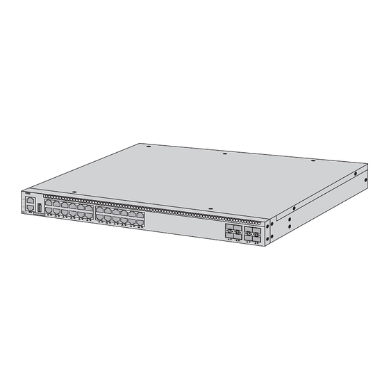
Page 3: Hardware Overview
Hardware Overview Front Panel Ports CONSOLE (CON) S5800-24T8S 10 11 14 15 16 17 18 19 22 23 RJ45 (1-24) 10G SFP+ (25-32) Ports Description 10G SFP+ (25-32) SFP+ ports for 10G connection RJ45 (1-24) 10/100/1000 Base-T ports for Ethernet connection... -
Page 4: Installation Requirements
LEDs State Description Solid Green The 1G port is connected. 1G packets are being received and transmitted. Blinking Green RJ45 Solid Orange The port is connected at 10G/100G. (1-24) Blingking Orange 10G/100G packets are being received and transmitted. The port is not connected. The 10G port is connected. - Page 5 Safety Precautions: Ensure that there are some spaces at the inlet and outlet of the switch for heat dissipation of the switch. Ensure that the rack and the working platform are rm enough to support the weight of the switch and its accessories for installation. Ensure that the rack and the working platform are well-earthed.
-
Page 6: Mounting The Switch
Mounting the Switch Desk Mounting 1. Attach four rubber pads to the bottom. 2. Place the switch on a desk. NOTE: 1. A 10cm space around the switch is left for heat dissipation. 2. Do not place heavy objects on the switch. Rack Mounting 1. -
Page 7: Grounding The Switch
2. Attach the switch to the rack with M6 screws and cage nuts. Grounding the Switch 1. Connect one end of the grounding cable to a proper earth ground, such as the rack in which the switch is mounted. 2. Secure the grounding lug to the grounding point on the back of the switch with washers and the screw. -
Page 8: Connecting The Sfp+ Ports
Connecting the RJ45 Ports 1. Connect an Ethernet cable to the 1G Base-T port. 2. Connect the other end of the Ethernet cable to a network device. Connecting the SFP+ Ports 1. Plug the compatible SFP+ transceiver into the SFP+ port. 2. -
Page 9: Connecting The Console Port
Connecting the Console Port 1. Insert the RJ45 connector of the console cable into the console port on the switch. 2. Connect the DB9 female connector of the console cable to the serial port on the computer. Connecting the ETH Port 1. -
Page 10: Connecting The Usb Port
Connecting the USB Port Insert the Universal Serial Bus (USB) ash disk to the USB port for software and con guration backup and o ine software upgrade. Connecting the Power 1. Plug the AC Power cord into the power port on the switch. 2. - Page 11 Con guring the Switch Con guring the Switch Using the Web-Based Interface Step 1: Connect a computer to the Ethernet port of the switch using the network cable. Step 2: Set the IP address of the computer to 192.168.1.X (X is any number from 2 to 254). Step 3: Open a browser, type http://192.168.1.1 and enter the default username and password, admin/admin.
-
Page 12: Troubleshooting
Con guring the Switch Using the Console Port Step 1: Connect a computer to the console port of the switch using the console cable. Step 2: Start the terminal simulation software, such as HyperTerminal on the computer. Step 3: Set the parameters of the HyperTerminal: Baud rate to 115200, Data bits to 8, Parity to None, and Stop bits to 1. -
Page 13: User Password Lost
User Password Lost If the system password is lost or forgotten, the following method can be used to reset the password: Enter uBoot operation mode. Start the system by typing the boot_ ash_nopass order under uBoot operation mode. Power System Troubleshooting When the SYS indicator is o , please check if: The power line of the switch is connected correctly. -
Page 14: Online Resources
Product Warranty FS ensures our customers that for any damage or faulty items due to our workmanship, we will o er a free return within 30 days from the day you receive your goods. This excludes any custom made items or tailored solutions. - Page 15 Einführung Vielen Dank, dass Sie sich für den S5800-24T8S Ethernet L3 Switch entschieden haben. Diese Anleitung soll Sie mit dem Aufbau des Switches vertraut machen und beschreibt, wie Sie ihn in Ihrem Netzwerk einsetzen können. S5800-24T8S 10 11 14 15...
- Page 16 Hardware-Übersicht Ports an der Vorderseite CONSOLE (CON) S5800-24T8S 10 11 14 15 16 17 18 19 22 23 RJ45 (1-24) 10G SFP+ (25-32) Ports Beschreibung 10G SFP+ (25-32) SFP+Ports für die 10G-Verbindung RJ45 (1-24) 10/100/1000 Base-T-Ports für die Ethernet-Verbindung Ein RJ45-Console-Port für die serielle Verwaltung...
- Page 17 LEDs Status Beschreibung Durchgehend grün Der 1G-Port ist verbunden. Es werden 1G-Pakete empfangen und übertragen. Blinkt grün RJ45 Durchgehend orange Der Port ist mit 10G/100G verbunden. (1-24) Es werden 10G/100G-Pakete empfangen und Blinkt orange übertragen. Der Port ist nicht verbunden. Durchgehend grün Der 10G-Port ist verbunden.
- Page 18 Betriebsumgebung: Achten Sie darauf, dass am Ein- und Ausgang des Switches genügend Platz für die Wärmeableitung vorhanden ist. Stellen Sie sicher, dass das Rack und die Arbeitsplattform stabil genug sind, um das Gewicht des Switches und des jeweiligen Zubehörs für die Installation zu tragen. Stellen Sie sicher, dass das Rack und die Arbeitsplattform gut geerdet sind.
-
Page 19: Montage Des Switches
Montage des Switches Tischmontage 1. Bringen Sie vier Gummipads an der Unterseite an. 2. Platzieren Sie den Switch auf einem Tisch. HINWEIS: 1. Für die Wärmeableitung sollte ein Platz von 10 cm um den Switch herum freigehalten werden. 2. Stellen Sie keine schweren Gegenstände auf den Switch. Rack-Montage 1. - Page 20 2. Bringen Sie den Switch am Rack mit den M6-Schrauben und Kä gmuttern an. Erdung des Switches 1. Schließen Sie ein Ende des Erdungskabels an eine geeignete Erdung an, z. B. an das Rack, in dem der Switch montiert ist. 2.
- Page 21 Anschließen der RJ45-Ports 1. Schließen Sie ein Ethernet-Kabel an den 1G Base-T-Port an. 2. Schließen Sie das andere Ende des Ethernet-Kabels an ein Netzwerkgerät an. Anschließen der SFP+-Ports 1. Stecken Sie den kompatiblen SFP+-Transceiver in den SFP+-Port. 2. Schließen Sie ein LWL-Kabel an den Transceiver-Port an. Schließen Sie dann das andere Ende des Kabels an ein anderes Glasfasergerät an.
- Page 22 Anschließen des Console-Ports 1. Stecken Sie den RJ45-Steckverbinder des Console-Kabels in den Console-Port des Switches. 2. Verbinden Sie die DB9-Buchse des Console-Kabels mit dem seriellen Port des Computers. Anschließen des ETH-Ports 1. Schließen Sie ein Ende eines standardmäßigen RJ45-Ethernet-Kabels an den Ethernet-Port eines Computers an.
-
Page 23: Anschließen Der Stromversorgung
Anschließen des USB-Ports Stecken Sie das USB-Laufwerk (Universal Serial Bus) in den USB-Port ein, um Software und Kon guration zu sichern und die Software o ine zu aktualisieren. Anschließen der Stromversorgung 1. Schließen Sie das Netzkabel an den Strom-Port des Switches an. 2. - Page 24 Kon gurieren des Switches Kon gurieren des Switches mithilfe der webbasierten Schnittstelle Schritt 1: Schließen Sie einen Computer über ein Netzwerkkabel an den Ethernet-Port des Switches an. Schritt 2: Stellen Sie die IP-Adresse des Computers auf 192.168.1.X ein (X ist eine beliebige Zahl zwischen 2 und 254).
-
Page 25: Fehlerbehebung
Kon gurieren des Switches über den Console-Port Schritt 1: Schließen Sie einen Computer über das Console-Kabel an den Console-Port des Switches an. Schritt 2: Starten Sie die Terminalsimulationssoftware, z. B. HyperTerminal, auf dem Computer. Schritt 3: Stellen Sie die Parameter von HyperTerminal ein: Baud rate auf 115200, Data bits auf 8, Parity auf None und Stop bits auf 1. - Page 26 Nutzerpasswort verloren Wenn Sie das Systempasswort verloren oder vergessen haben, können Sie es mit der folgenden Methode zurücksetzen: Rufen Sie den uBoot-Betriebsmodus auf. Starten Sie das System, indem Sie im uBoot-Modus den Befehl boot_ ash_nopass eingeben. Fehlerbehebung bei der Stromversorgung Wenn die SYS-Anzeige aus ist, überprüfen Sie bitte, ob: Die Stromleitung des Schalters richtig angeschlossen ist.
- Page 27 Kontakt https://www.fs.com/de/contact_us.html Produktgarantie FS garantiert seinen Kunden, dass wir bei Schäden oder fehlerhaften Artikeln, die auf unsere Verarbeitung zurückzuführen sind, eine kostenlose Rückgabe innerhalb von 30 Tagen nach Erhalt der Ware anbieten. Dies gilt nicht für Sonderanfertigungen oder maßgeschneiderte Lösungen.
- Page 28 Introduction Nous vous remercions d'avoir choisi le Switch Ethernet L3 S5800-24T8S. Ce guide est conçu pour vous familiariser avec la con guration du switch et décrit comment procéder à son déploiement. S5800-24T8S 10 11 14 15 16 17 18 19...
-
Page 29: Présentation Du Matériel
Présentation du Matériel Ports du Panneau Frontal CONSOLE (CON) S5800-24T8S 10 11 14 15 16 17 18 19 22 23 RJ45 (1-24) 10G SFP+ (25-32) Ports Description Ports SFP+ pour connexion 10G 10G SFP+ (25-32) RJ45 (1-24) Ports 10/100/1000 Base-T pour la connexion Ethernet Port console RJ45 pour la gestion en série... -
Page 30: Panneau Arrière
Description État Vert Le port 1G est connecté. Des paquets 1G sont reçus et transmis. Vert Clignotant RJ45 Le port est connecté à 10G/100G. Orange (1-24) Des paquets 10G/100G sont reçus et transmis. Orange Clignotant Le port n'est pas connecté. Éteint Le port 10G est connecté. - Page 31 Environnement du Site : Veillez à ce qu'il y ait su samment d'espace au niveau de l'entrée et sortie du switch pour permettre la dissipation de la chaleur. Assurez-vous que le rack et la plateforme de travail soient su samment stables pour supporter le poids du switch et de ses accessoires lors de l'installation.
-
Page 32: Installation En Rack
Installation du Switch Installation sur Bureau ou Surface Plane 1. Fixez quatre patins en caoutchouc à la base du switch. 2. Placez le switch sur un bureau ou surface plane. NOTE : 1. Prévoyez un espace de 10cm autour du switch pour la dissipation de la chaleur. - Page 33 2. Fixez le switch au rack à l'aide de vis M6 et d'écrous à cage. Mise à la Terre du Switch 1. Connectez une extrémité du câble de mise à la terre à une terre appropriée, telle que le rack dans lequel le switch est installé. 2.
- Page 34 Connexion des Ports RJ45 1. Connectez un câble Ethernet au port 1G Base-T. 2. Connectez l'autre extrémité du câble Ethernet à un périphérique réseau. Connexion des Ports SFP+ 1. Branchez l'émetteur-récepteur SFP+ compatible au port SFP+. 2. Connectez un câble à bre optique au port de l'émetteur-récepteur. Connectez ensuite l'autre extrémité...
- Page 35 Connexion du Port de Console 1. Insérez le connecteur RJ45 du câble de console au port de console du switch. 2. Connectez le connecteur femelle DB9 du câble de console au port série de l'ordinateur. Connexion du Port ETH 1. Connectez une extrémité d'un câble Ethernet RJ45 standard au port Ethernet d'un ordinateur.
-
Page 36: Connexion De L'alimentation
Connexion du Port USB Insérez le dispositif USB (Universal Serial Bus) dans le port USB pour la sauvegarde, la con guration ou la mise à jour du logiciel hors ligne. Connexion de l'Alimentation 1. Branchez le câble d'Alimentation AC dans le port d'alimentation du switch. 2. - Page 37 Con guration du Switch Con guration du Switch à l'Aide de l'Interface Web Étape 1 : Connectez un ordinateur au port Ethernet du switch à l'aide du câble réseau. Étape 2 : Dé nissez l'adresse IP de l'ordinateur sur 192.168.1.X (X est un nombre compris entre 2 et 254).
-
Page 38: Dépannage
Con guration du Switch à l'Aide du Port de Console Étape 1 : Connectez un ordinateur au port de console du switch à l'aide du câble de console. Étape 2 : Lancez le logiciel de simulation HyperTerminal sur l'ordinateur. Étape 3 : Dé nissez les paramètres de l'HyperTerminal : 115200 pour le Baud rate, 8 pour les Data bits, None pour la Parity et 1 pour les Stop bits. - Page 39 Perte du Mot de Passe Utilisateur Si le mot de passe du système est perdu ou oublié, la méthode suivante peut être utilisée pour réinitialiser le mot de passe : Entrez dans le mode d'opération uBoot. Démarrez le système en tapant la commande boot_ ash_nopass dans le mode d'opération uBoot.
-
Page 40: Garantie Du Produit
Garantie du Produit FS garantit à ses clients que tout article endommagé ou défectueux en raison de sa fabrication pourra être retourné gratuitement dans un délai de 30 jours à compter de la date de réception de la marchandise. Cette garantie ne s'applique pas aux articles fabriqués sur mesure ou aux solutions personnalisées. - Page 41 イントロダクション S����-��T�SイーサネットL�スイッチをお選びいただきありがとうございます。このガイ ドは、スイッチのレイアウトに慣れることを目的としており、ネットワークにスイッチを 導入する方法について説明します。 S5800-24T8S 10 11 14 15 16 17 18 19 22 23 S5800-24T8S アクセサリー 電源コード x� コンソールケーブル x� ネットワークケーブル x� アース線 x� ゴムパッド x� M�ネジ x�� 取り付けブラケット x� M�ネジ x� M�ケージナット x�...
- Page 42 ハードウェア概要 フロントパネルポート CONSOLE (CON) S5800-24T8S 10 11 14 15 16 17 18 19 22 23 RJ45 (1-24) 10G SFP+ (25-32) ポート 説明 ��G接続用SFP+ポート 10G SFP+ (25-32) イーサネット接続用��/���/���� Base-Tポート RJ45 (1-24) シリアル管理用RJ��コンソールポート CONSOLE フロントパネルLED S5800-24T8S 10 11 14 15 16 17...
- Page 43 状態 説明 �Gポートが接続されています。 緑色点灯 緑色点滅 �Gパケットが送受信されています。 オレンジ色点灯 ポートは��G/���Gで接続されています。 RJ45 (1-24) ��G/���Gパケットが送受信されています。 オレンジ色点滅 ポートが接続されていません。 オフ ��Gポートが接続されています。 緑色点灯 ��Gパケットが送受信されています。 緑色点滅 �Gポートが接続されています。 10G SFP+ オレンジ色点灯 (25-32) �Gパケットが送受信されています。 オレンジ色点滅 ポートが接続されていません。 オフ バックパネル 接地点 ファンスロット 電源 (AC) 設置要件 設置する前に、次のものが揃っていることを確認してください: プラスドライバー マイナスドライバー ESD用リストストラップ 安全に関する注意事項: 装置をクリーニングする前に、電源を取り外す必要があります。装置を液体で洗浄し ないでください。 スイッチは適切な電圧の下で正常に動作するため、動作電圧がスイッチに記された電...
- Page 44 サイト環境: スイッチの放熱のために、スイッチの入口と出口にスペースがあることを確認してく ださい。 ラックと作業台が、スイッチとそのアクセサリの設置重量を支えるのに十分な固さで あることを確認してください。 ラックと作業台が適切に接地されていることを確認してください。 設置場所の温度は�~��℃、湿度は��%~��%に保ってください。 埃の多い環境には設置しないでください。 機器室は、SO 、H S、NH 、Cl などの有害なガスの侵入から保護する必要があります。 � � � � 本スイッチが動作する場所は、強電無線送信所、レーダー送信所、高周波、大電流機 器から遠ざけてください。...
- Page 45 スイッチの取り付け デスクへの取り付け �. 底面に�つのゴムパッドを取り付けます。 �. スイッチを机の上に置きます。 注: �. スイッチ周囲には放熱のため��cm程度のスペースを設けております。 �. スイッチの上に重いものを置かないでください。 ラック取り付け �. 取り付けブラケットをM�ネジで�つの側面に固定します。...
- Page 46 �. スイッチをM�ネジとケージナットでラックに取り付けます。 スイッチの接地 �. アース線の一端を、スイッチが取り付けられているラックなどの適切なアースに接続し ます。 �. 接地ラグをスイッチ背面の接地ポイントにワッシャとネジで固定します。 ご注意: すべての電源接続が切断されていない限り、アース接続を切断しないで ください。...
- Page 47 RJ��ポートの接続 �. イーサネットケーブルを�G Base-Tポートに接続します。 �. イーサネットケーブルのもう一方の端をネットワークデバイスに接続します。 SFP+ポートの接続 �. 互換性のあるSFP+トランシーバーをSFP+ポートに差し込みます。 �. トランシーバーポートに光ファイバケーブルを接続します。次に、ケーブルのもう一方 の端を別の光ファイバ機器に接続します。...
- Page 48 コンソールポートの接続 �. コンソールケーブルのRJ��コネクタをスイッチのコンソールポートに挿入します。 �. コンソールケーブルのDB�メスコネクタをコンピュータのシリアルポートに接続します。 ETHポートの接続 �. 標準RJ��イーサネットケーブルの一端をコンピュータのイーサネットポートに接続しま す。 �. ケーブルのもう一方の端をスイッチのETHポートに接続します。...
- Page 49 USBポートの接続 ユニバーサルシリアルバス(USB)フラッシュディスクをUSBポートに挿入し、ソフトウ ェアと構成のバックアップおよびオフラインソフトウェアアップグレードを行います。 電源の接続 �. AC電源コードをスイッチの電源ポートに差し込みます。 �. 電源コードのもう一方をAC電源に接続します。...
- Page 50 スイッチの設定 ウェブベースのインターフェイスを使用したスイッチの設定 ステップ�: ネットワークケーブルを使用して、コンピュータをスイッチのイーサネットポ ートに接続します。 ステップ�: コンピュータのIPアドレスを���.���.�.Xに設定します(「X」は�から���まで の任意の数字)。 ステップ�: ブラウザーを開き、「http://���.���.�.�」と入力し、デフォルトのユーザー名 とパスワードadmin/adminを入力します。 ステップ�:「Login」をクリックして、ウェブベースの設定ページを表示します。...
- Page 51 コンソールポートを使用したスイッチの設定 ステップ�: コンソールケーブルを使用して、コンピュータをスイッチのコンソールポート に接続します。 ステップ�: コンピュータ上でハイパーターミナルなどの端末シミュレーションソフトを起 動します。 ステップ�: ハイパーターミナルのパラメーターを設定する:ボーレートを������、データ ビットを�、パリティをなし、ストップビットを�に設定します。 Quick Connect Protocol: Serial The port may be manually entered or selected from the list. Port: COM3 115200 Baud rate: Flow Control DTR/DSR Data bits: RTS/CTS Parity: None XON/XOFF Stop bits: Name of pipe: Show quick connect on startup Save session...
- Page 52 ユーザーパスワード紛失 システム・パスワードを紛失または忘れた場合、以下の方法でパスワードをリセットする ことができます: uBoot動作モードに入ります。 uBootオペレーションモードでboot_flash_nopass命令を入力してシステムを起動し ます。 電力システムのトラブルシューティング SYSインジケーターが消灯している場合は、次のことを確認してください: スイッチの電源線は正しく接続されているかどうか。 スイッチのESPは、スイッチが必要とする電力と一致するかどうか。 設定システムのトラブルシューティング 電源投入後、コンフィギュレーションターミナルの表示情報が表示されない場合は、 電源が正常か、コンソールポートのケーブルが正しく接続されているかを確認してく ださい。 設定システムにハッシュが表示される場合は、端末(スーパー端末など)のパラメー タ設定を確認してください:ボーレート:������、データビット:�、パリティ: なし、 ストップビット:�、フロー制御:NA、ターミナルエミュレーションの選択:VT���。...
- Page 53 オンラインリソース ダウンロード https://www.fs.com/jp/products_support.html ヘルプセンター https://www.fs.com/jp/service/fs_support.html お問い合わせ https://www.fs.com/jp/contact_us.html 製品保証 FSは、お客様が弊社の仕上がりに起因する損傷または不良品について、製品を受け取った 日から��日以内に無料で返品できることを保証します。これには、カスタムメイドのアイ テムやカスタマイズされたソリューションは含まれません。 保証: S����-��T�Sスイッチには、材料または製造上の欠陥に対する�年間の限 定保証が付いています。保証の詳細については、以下のサイトをご参照くださ い: https://www.fs.com/jp/policies/warranty.html 返品: 返品を希望される場合は、以下のサイトで返品方法に関する情報をご確認 ください: https://www.fs.com/jp/policies/day_return_policy.html...
- Page 54 Q.C. PASSED Copyright © 2023 FS.COM All Rights Reserved.
Need help?
Do you have a question about the S5800-24T8S and is the answer not in the manual?
Questions and answers