
Related Manuals for Nordson EX Series


Summary of Contents for Nordson EX Series
- Page 1 Extruder EX EX .. UFM Manual P/N 7179048_04 - English - Edition 12/19 NORDSON ENGINEERING GMBH LÜNEBURG GERMANY...
- Page 2 Micro-Meter, MicroSet, Microshot, Millenium, MiniBlue, Mini Squirt, Moist-Cure, Mountaingate, MultiScan, NexJet, No-Drip, Nordson, Nordson-stylized, Nordson and Arc, nXheat, NYTVision, OptiMix, Optima, Optimum, Package of Values, Paragon, PatternView, PermaFlo, PICO, PicoPulse, Plasmod, PluraFoam, Poly-Check, Polymer Solution Casting, Porous Coat, Posi-Dose, PowderGrid, Powderware, Precisecoat, PRIMARC, Printplus, Prism, ProBlue, ProBlue Liberty, Prodigy, Pro-Flo, Program-A-Bead, Program-A-Shot, Program-A-Stream, Program-A-Swirl, ProLink, Pro-Meter, Pro-Stream, Pulsar, Quantum, Ratio-Pak, RBX, ReadySet, Rhino, Saturn, Saturn with rings, Scoreguard, SC5, S.
-
Page 3: Table Of Contents
........1-11 EX / EX..UFM P/N 7179048_04 2019 Nordson Corporation... - Page 4 ....2-23 Using a Pressure Relief Valve to Prevent Overpressure Malfunction During Longer Breaks in Production ... 2-24 P/N 7179048_04 EX / EX..UFM 2019 Nordson Corporation...
- Page 5 ......3-19 Piston Pressure Switch KDS 05/120 ......3-20 EX / EX..UFM P/N 7179048_04 2019 Nordson Corporation...
- Page 6 ........4-11 P/N 7179048_04 EX / EX..UFM 2019 Nordson Corporation...
- Page 7 ........5-19 Replacing Sealing Kit P/N 7549606 ..... . 5-19 EX / EX..UFM P/N 7179048_04 2019 Nordson Corporation...
- Page 8 ....... 7-15 Motor Controller 8400 (Lenze) Spare Parts ....7-16 P/N 7179048_04 EX / EX..UFM 2019 Nordson Corporation...
- Page 9 ....... . . Determination of Foam Density ......EX / EX..UFM P/N 7179048_04 2019 Nordson Corporation...
- Page 10 VIII Table of Contents P/N 7179048_04 EX / EX..UFM 2019 Nordson Corporation...
-
Page 11: Safety
CAUTION! Indicates a potentially hazardous situation that, if not avoided, can result in minor or moderate personal injury. CAUTION! (Used without the safety alert symbol) Indicates a potentially hazardous situation that, if not avoided, can result in damage to equipment or property. Safe_PPA1011LUE_EN 2011 Nordson Corporation... -
Page 12: Responsibilities Of The Equipment Owner
Provide appropriate emergency and first aid equipment. Conduct safety inspections to ensure required practices are being followed. Re-evaluate safety practices and procedures whenever changes are made to the process or equipment. Safe_PPA1011LUE_EN 2011 Nordson Corporation... -
Page 13: User Qualifications
Do not modify the equipment. Do not use incompatible materials or unapproved auxiliary devices. Contact your Nordson representative if you have any questions on material compatibility or the use of non-standard auxiliary devices. Safe_PPA1011LUE_EN 2011 Nordson Corporation... -
Page 14: Instructions And Safety Messages
Familiarize yourself with the location and meaning of the safety warning labels and tags affixed to the equipment. Refer to Safety Labels and Tags at the end of this section. If you are unsure of how to use the equipment, contact your Nordson representative for assistance. Installation Practices Install the equipment in accordance with the instructions provided in this document and in the documentation provided with auxiliary devices. -
Page 15: Maintenance And Repair Practices
Read and comply with the manufacturer's instructions and the MSDS supplied with equipment cleaning compounds. NOTE: MSDSs for cleaning compounds that are sold by Nordson are available at www.nordson.com or by calling your Nordson representative. Confirm the correct operation of all safety devices before placing the equipment back into operation. -
Page 16: Equipment Shutdown
PLC, etc.). 2. Disconnect the input signal wiring to the applicator solenoid valve(s). 3. Reduce the air pressure to the applicator solenoid valve(s) to zero; then relieve the residual air pressure between the regulator and the applicator. Safe_PPA1011LUE_EN 2011 Nordson Corporation... -
Page 17: General Safety Warnings And Cautions
General Safety Warnings and Cautions Table 1-1 contains the general safety warnings and cautions that apply to Nordson hot melt and cold adhesive equipment. Review the table and carefully read all of the warnings or cautions that apply to the type of equipment described in this manual. - Page 18 WARNING! Risk of fire or explosion! Nordson adhesive equipment is not rated for use in explosive environments and has not been cerfified for the ATEX directive or as nonincendive. In addition, this equipment...
- Page 19 CAUTION! Nordson hot melt equipment is factory tested with Nordson Type R fluid that contains polyester adipate plasticizer. Certain hot melt materials can react with Type R fluid and form a solid gum that can clog the equipment.
-
Page 20: Other Safety Precautions
3. Do NOT attempt to remove the solidified hot melt from your skin. 4. In case of severe burns, treat for shock. 5. Seek expert medical attention immediately. Give the MSDS for the hot melt to the medical personnel providing treatment. Safe_PPA1011LUE_EN 2011 Nordson Corporation... -
Page 21: Safety Labels And Tags
CAUTION: Hot surface. Failure to observe can cause burns. 421461 ATTENTION: Risk of being drawn in by screw. Do not operate the extruder without the hopper. Do not operate the hopper without the protective grating when filling manually. EX / EX..UFM P/N 7179048_04 2019 Nordson Corporation... - Page 22 1-12 Safety Instructions EX / EX..UFM P/N 7179048_04 2019 Nordson Corporation...
-
Page 23: Introduction
Any other use is considered to be unintended. Nordson will not be liable for personal injury and/or property damage resulting from unintended use. -
Page 24: Restricted Use
As an alternative, specially hardened pumps with relatively longer serviceable lives can be supplied. When in doubt, please contact your Nordson representative. Residual Risks In the design of the unit, every measure was taken to protect personnel from potential danger. -
Page 25: Note On Manual
Note on Manual The actual extruder model can deviate from the illustrations. An application head is referred to as an applicator in newer Nordson literature. Pilot voltage is also referred to as key-to-line, regardless of the type of pilot voltage. -
Page 26: Id Plate
Lilienthalstr. 6 LISTED D 21337 Lüneburg - Germany Year Serial No: www.nordson.com Fig. 2-1 Example Designation for Nordson extruder Order number Configuration code Electrical connection, operating voltage, line voltage frequency, melter fuse protection Serial number Year Month G July H August... -
Page 27: Configuration Code
Maximum 40 l/h per pump Maximum 80 l/h per pump Maximum 160 l/h per pump Hose connection 8 mm Hose connection 13 mm Hose connection 16 mm Hose connection 20 mm Continued ... EX / EX..UFM P/N 7179048_04 2019 Nordson Corporation... - Page 28 Control panel with 5.7" screen Control panel with 10" screen I/O interface (no field bus interface) Profibus-DP (* was ”P” before SEP 2017) ControlNet EtherNet/IP Profinet IO (** was ”#” before SEP 2017) P/N 7179048_04 EX / EX..UFM 2019 Nordson Corporation...
-
Page 29: Function
6 Cylinder feed cooling 10 Temperature sensors 2 Feed cylinder with end flange 7 Level detection 11 Access hole 3 Electrical gear motor to drive the 8 Pressure sensor screw conveyor 4 Screw conveyor EX / EX..UFM P/N 7179048_04 2019 Nordson Corporation... -
Page 30: Description Of Components
2 Drain plug 7 Flange 12 Hopper 3 Screw cylinder 8 Support block 13 Hopper lid 4 Temperature sensor 9 Piston pressure switch 14 Level sensor 5 Heating cuff 10 Pressure sensor P/N 7179048_04 EX / EX..UFM 2019 Nordson Corporation... -
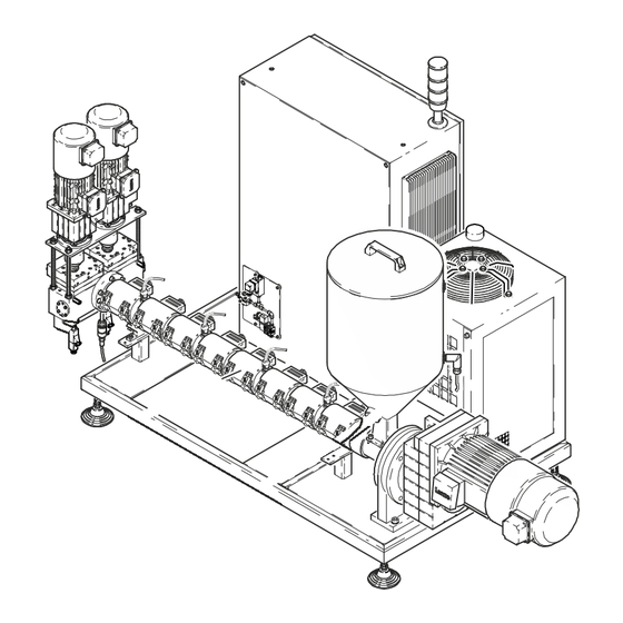
Page 31: Illustration Of Ex-060
2 Compressed air connection 6 Air conditioning unit 10 Gas supply unit 3 Belt 7 Pressure switch 11 Loading and foam pump 4 Thrust bearing 8 Piston pressure switch 12 Foam station servomotor EX / EX..UFM P/N 7179048_04 2019 Nordson Corporation... - Page 32 7 Cooling element (not on all units) 12 Enable / fault 3 EMERGENCY OFF button 8 Main switch 13 Key-to-line mode 4 Electrical cabinet ventilation 9 Receptacle 14 Light tower 5 Power cable 10 Customer I/O P/N 7179048_04 EX / EX..UFM 2019 Nordson Corporation...
-
Page 33: Protective Devices
When the trigger temperature is exceeded, the heating circuit is interrupted. The fuses are mounted on each controlled heating circuit, with the exception of the screw. EX / EX..UFM P/N 7179048_04 2019 Nordson Corporation... -
Page 34: Pneumatic Assembly And Pneumatic Bypass
Piston Pressure Switch The piston pressure switch (2) constantly monitors the current adhesive pressure and switches off the drive at the preset limit. Fig. 2-7 Example with metering station P/N 7179048_04 EX / EX..UFM 2019 Nordson Corporation... -
Page 35: Mechanical Bypass
There is a compression spring (3) in the bypass valve. If the set pressure is exceeded, the adhesive circulates in the bypass plate. For information on how to set the pressure, refer to the section Installation . Fig. 2-8 EX / EX..UFM P/N 7179048_04 2019 Nordson Corporation... -
Page 36: Drive
Hopper almost empty Hopper full Filling Area The filling area consists of a water-cooled filling piece and a filling hopper. The granulate is supplied through the hopper. The hopper is release coated. P/N 7179048_04 EX / EX..UFM 2019 Nordson Corporation... -
Page 37: Screw Conveyor
Temperature sensors compile the temperature values. Air Cooling Some models require screw cylinder air cooling. The heating cuffs or fan are switched on and off for each heating zone, depending on the temperature. EX / EX..UFM P/N 7179048_04 2019 Nordson Corporation... -
Page 38: Cylinder Feed Cooling
NOTE: Cold means approx. 15 to 20 ° C and is standard for the adhesives that are normally processed with Nordson extruders. The water chillers offered by Nordson are designed for this temperature range. -
Page 39: Main Switch
Systems with a black main switch are normally supplied with power by a higher-ranking system; the higher-ranking main switch is on that system. The black main switch does not serve as an EMERGENCY OFF feature. Connected components can still be energized! EX / EX..UFM P/N 7179048_04 2019 Nordson Corporation... -
Page 40: Power Switch (With Overcurrent Shutdown)
When the electrical cabinet requires work that can be performed only when line voltage is supplied, override the door lock with a screwdriver. Refer to the illustration at left. Then close the door again. Then the door is locked again. P/N 7179048_04 EX / EX..UFM 2019 Nordson Corporation... -
Page 41: Emergency Off Button
The electrical cabinet can be opened for installation, maintenance and repair. Store the included key such that it is accessible only to qualified and authorized personnel. The system may not be operated when the electrical cabinet is open. EX / EX..UFM P/N 7179048_04 2019 Nordson Corporation... -
Page 42: Control Panel
Field Bus Interface (Option) The field bus interface enables remote operation by a higher-ranking control unit (master). Nordson systems on the field bus are always slaves. P/N 7179048_04 EX / EX..UFM 2019 Nordson Corporation... -
Page 43: Metering Station (Option)
When they have been triggered, these irreversible overtemperature fuses have to be replaced. Thermostat Thermostats are also used in place of fuses. Take into consideration the switchoff temperature when ordering spare parts (Refer to extruder parts list). EX / EX..UFM P/N 7179048_04 2019 Nordson Corporation... -
Page 44: Foam Station Ultra Foammix (Special)
The gas expands during application and foam forms. Refer to Appendix D, Determination of Foam Density . Foam pump Loading pump Gas supply unit Access hole (extruder screw) Pressure sensor Mixer fan (foam station outlet) Fig. 2-10 P/N 7179048_04 EX / EX..UFM 2019 Nordson Corporation... -
Page 45: Description Of Function
). (900-270):900 or (900-230):900 means that the proportion of foam is 70 ... 74 %. The foam rate describes the ratio between the loading pump speed and the foam pump speed. Continued ... EX / EX..UFM P/N 7179048_04 2019 Nordson Corporation... -
Page 46: Using A Pressure Relief Valve To Prevent Overpressure Malfunction During Longer Breaks In Production
(screw not moving). When the set pressure is exceeded, the adhesive is conveyed into the container before it even reaches the foam station. Fig. 2-12 Solenoid valve (left) - pressure relief valve with container P/N 7179048_04 EX / EX..UFM 2019 Nordson Corporation... -
Page 47: Installation
Unpack carefully. Then check for any damage caused during shipping. Transport damage must be documented by the shipper and immediately reported to Nordson. Save the pallet and angle brackets for later use. Reuse packaging materials or dispose of properly according to local regulations. -
Page 48: Transport
Depending on the size of the extruder, there are eye-bolts and/or other fittings for securing to the forks on the forklift. CAUTION: Larger extruders can weigh several tons. Weight approx. 4500 kg Forklift forks Fig. 3-1 Example of EX160 P/N 7179048_04 EX / EX..UFM 2019 Nordson Corporation... -
Page 49: Lifting The Metering Station
CAUTION: In there is an eye-bolt in the middle of the metering station, the eye-bolt plate nuts may only be fingertight; otherwise heat expansion will cause the metering station to warp. Do not overtighten nuts Fig. 3-2 Example P/N 7188094 EX / EX..UFM P/N 7179048_04 2019 Nordson Corporation... -
Page 50: Installation Requirements
The instructions contained in this section are intended for personnel with experience/authorization in the following fields: Application methods with hot melt adhesive or similar materials Industrial electrical wiring of power and control lines Industrial mechanical installation General knowledge of process control. P/N 7179048_04 EX / EX..UFM 2019 Nordson Corporation... -
Page 51: Setting Up
3. Two hours after the unit is “Ready” and is hot, adjust the screws on each side such that they are 0.3 mm away from the cylinder (heat expansion). Fig. 3-4 EX / EX..UFM P/N 7179048_04 2019 Nordson Corporation... -
Page 52: Electrical Connections
If the transformer cable is already connected to its circuit breaker and threaded to the outside but not yet connected to the transformer, there is dangerous voltage at the end of the cable when the extruder is connected to the power supply. P/N 7179048_04 EX / EX..UFM 2019 Nordson Corporation... -
Page 53: Line Voltage
Either plug in the bridge or integrate into the EMERGENCY OFF chain. If this is not done, the system has the same status as if the module were triggered, meaning that it cannot be started. EX / EX..UFM P/N 7179048_04 2019 Nordson Corporation... -
Page 54: Connecting Interfaces
Higher signal voltages are possible only with a coupler component. The tach generator adjustment board (Refer to Appendix A) used previously is no longer supplied. P/N 7588044 (replacement for 7140205) Coupler component P/N 7140205: 0-200/0-10V Fig. 3-5 P/N 7179048_04 EX / EX..UFM 2019 Nordson Corporation... -
Page 55: Field Bus (Option)
The Profibus-DP/DP coupler P/N 7115660 and the Profinet IO PN/PN coupler P/N 7595044 (replacement for P/N 7188034) are offered for Siemens. These couplers are described in the document Nordson Melters on Field Bus with Siemens (Master) PLC , available in German (P/N 7580294) and in English (P/N 7580295). -
Page 56: Analog Modem For Pc Connection
2. Connect the analog modem (connection Line ) and the analog telephone socket with a telephone cable. 3. Switch on the extruder. 4. Call Nordson. Please have the phone number of the modem connection and the system serial number handy so that a service technician can dial into the system and have the corresponding documentation at hand. -
Page 57: Connecting Heated Hose
If cold adhesive can be found in the hose connection, the components (1, 2) must be heated until the adhesive softens (approx. 70 C/158 F, depending on adhesive). CAUTION: Nordson systems are usually subjected to extensive testing prior to shipment. There may be some of the test material left in the hose connection. -
Page 58: Disconnecting
3. Switch off the extruder screw motor. 4. Allow the foam station pumps to continue to turn until the adhesive pressure has returned to 0 bar. 5. Properly dispose of adhesive according to local regulations. P/N 7179048_04 EX / EX..UFM 2019 Nordson Corporation... -
Page 59: Electrical Cabinet Cooling Unit
Remove cover 1: LED ready (green) 2: LED alarm (red) Behind the cover 3: Adjust temperature setpoint 4: Reset button For information on installation, operation and maintenance, refer to the separate manufacturer's manual EX / EX..UFM P/N 7179048_04 2019 Nordson Corporation... -
Page 60: Connecting Water Chiller (Option)
Use treated water to cool the cylinder feed with a water chiller. Refer to Water Specification . Wasserrückkühlgerät Water chiller Heizbänder Heating cuffs Kühlwasseranschluss Cooling water connection Fig. 3-6 Water chiller connection P/N 7179048_04 EX / EX..UFM 2019 Nordson Corporation... -
Page 61: Water Installation
CAUTION: A corrosion protection agent must be added to the cooling water. The water chiller unit is supplied without cooling water: Nordson recommends the anti-corrosion agent BCG K , made by the company BaCoGa Technik GmbH. Observe the safety data sheet. -
Page 62: Motor Controller With Cold Plate Cooling
Cooling water supply and recirculation on an EX030..UFM Cold Plate cooling is used mainly in the extruder sizes EX030 and EX060. Measurement and Control Diagram Cold Plate Fig. 3-9 Example of foam extruder with Cold Plate cooling P/N 7179048_04 EX / EX..UFM 2019 Nordson Corporation... - Page 63 3-17 Installation Cold Plate connections Cooling water feed zone Cooling water connection Fig. 3-10 EX / EX..UFM P/N 7179048_04 2019 Nordson Corporation...
-
Page 64: Measurement And Control Diagram (System)
3-18 Installation Measurement and Control Diagram (System) Fig. 3-11 Example of a system P/N 7179048_04 EX / EX..UFM 2019 Nordson Corporation... -
Page 65: Adjusting Mechanical Bypass Valve
1. Use the parts list to determine which bypass valve is installed: e.g. P/N 7058053: Distance 24 mm = 60 bar NOTE: This information applies to new compression springs. Wear causes deviations. EX / EX..UFM P/N 7179048_04 2019 Nordson Corporation... -
Page 66: Piston Pressure Switch Kds 05/120
(height and lateral offset) is important. Foam Station Ultra FoamMix (Special) Pressure relief valve with drip pan Fig. 3-13 P/N 7179048_04 EX / EX..UFM 2019 Nordson Corporation... - Page 67 Pressure relief valve with drip pan (Fig. 3-13) A 9 - 9 B 9 - 9 Air diverter for pressure relief valve Solenoid valve (pressure relief valve) Customer's connection Fig. 3-14 Example EX / EX..UFM P/N 7179048_04 2019 Nordson Corporation...
-
Page 68: Connecting Compressed Air Or Inert Gas
Mineral oil aerosols from the compressor air intake Dust and dirt particles from the compressor air intake Cooling and lubricating oil from the compressor Rust and abraded particles from the supply network. P/N 7179048_04 EX / EX..UFM 2019 Nordson Corporation... -
Page 69: Pressure Relief Valve With Drip Pan
(preliminary pressure of pumps). The control module opens when the screw stops AND the trigger pressure is reached. NOTE: The container must be checked daily and may need to be emptied several times per day. EX / EX..UFM P/N 7179048_04 2019 Nordson Corporation... -
Page 70: Measurement And Control Diagram (Foam Station)
M4.1= Mixer unit fan Legend Temperature sensor TIC= Temperature control circuit Level sensor PIC= Pressure control circuit Pressure display Electrical valve Overtemperature fuse Pressure switch Motor Fig. 3-16 Example of foam station P/N 7179048_04 EX / EX..UFM 2019 Nordson Corporation... -
Page 71: Operation
Always close the hopper lid immediately after filling, and store granulate not yet in the tank in a cool, dry place. Adhesive Expiration Date Do not use the adhesive when it has passed the expiration date. EX / EX..UFM P/N 7179048_04 2019 Nordson Corporation... -
Page 72: Important Upon Initial Startup
Compare the customer's connections to the wiring diagram Verify that the EMERGENCY OFF and safety switchoff devices, e.g. electrical overpressure fuses, function properly. The limits for warning, fault and switchoff should be adjusted according to the procedural conditions. P/N 7179048_04 EX / EX..UFM 2019 Nordson Corporation... -
Page 73: Initial Startup
Press the keys Arrow up and Arrow down simultaneously to leave the parameter level. E. Check the water level. When Using Own Cooling Connect the water supply and recirculation for cylinder feed cooling, and Water Supply open the water shutoff valve. EX / EX..UFM P/N 7179048_04 2019 Nordson Corporation... - Page 74 Put the lid back into place after filling. ATTENTION: Never use metal devices to attempt to crush granulate clumps in the screw feed zone during operation. Risk of injury and of destroying the extruder! P/N 7179048_04 EX / EX..UFM 2019 Nordson Corporation...
- Page 75 The maximum operating temperature for the product described here and the heated system components may not be exceeded. Nordson will grant no warranty and assume no liability for damage resulting from incorrect temperature settings. 8. Select automatic mode for production.
-
Page 76: Selecting Pressure Control Or Speed Control
The key Foam pump on/off switches the loading pump at the same time. Key Mixer on/off NOTE: Depending on which keys are selected or not, other operating elements will be visible or invisible. P/N 7179048_04 EX / EX..UFM 2019 Nordson Corporation... -
Page 77: Operation In Automatic Mode
Startup speed for filling mixer unit Adjust the setpoint speed of the mixer and the foam pump. Set the setpoint pressure PID parameters, pressure controller (password) The interface signal Start foam unit must be present. EX / EX..UFM P/N 7179048_04 2019 Nordson Corporation... -
Page 78: During Production
Temperatures that are too low are also detrimental to quality. If satisfactory results are achieved only by deviating from the stated processing temperature, please promptly contact a Nordson representative. Standby During Breaks Serves to protect the adhesive and to save energy during breaks in production. -
Page 79: Pressure Monitoring
(main contactor opens). Take into consideration the switchoff temperature of the overtemperature fuse (fuse or thermostat) when ordering spare parts. Refer to the extruder parts list. EX / EX..UFM P/N 7179048_04 2019 Nordson Corporation... -
Page 80: Switching System On/Off
3. Set the main switch on the extruder and on the optional water chiller to I/ON if necessary. 4. Wait until the system is ready. 5. Switch on the motor(s) via the interface. P/N 7179048_04 EX / EX..UFM 2019 Nordson Corporation... -
Page 81: Daily Shutdown
2. After standstill and before switching the unit on again, have the malfunction remedied by qualified personnel. Black Main Switch (Special Model) The black main switch does not serve as an EMERGENCY OFF feature. Connected components can still be switched on! EX / EX..UFM P/N 7179048_04 2019 Nordson Corporation... - Page 82 4-12 Operation P/N 7179048_04 EX / EX..UFM 2019 Nordson Corporation...
-
Page 83: Maintenance
ATTENTION: System and adhesive pressurized. Relieve the system of adhesive pressure before disconnecting pressurized components (e.g. hoses, pressure sensors). Failure to observe can result in serious burns. Refer to section Installation . EX / EX..UFM P/N 7179048_04 2019 Nordson Corporation... -
Page 84: Residual Current Device (Rcd) / Earth Leakage Circuit Breaker (Elcb)
Touch the test button “T” to check if the ELCB is functioning properly. This test does not serve as a substitute for measuring ground resistance or inspecting the ground conductor, both of which have to be performed separately. P/N 7179048_04 EX / EX..UFM 2019 Nordson Corporation... -
Page 85: Shutdown
5. Stop the extruder again and attach the hoses. Then the extruder can return to the normal operating mode. Fig. 5-2 With flange-mounted metering station Fig. 5-3 Without flange-mounted metering station EX / EX..UFM P/N 7179048_04 2019 Nordson Corporation... -
Page 86: Changing Type Of Adhesive
Unit part Activity Interval Entire unit External cleaning Daily Visual inspection for external damage Daily Cordset Inspect for damage Daily Cooling lines Inspect for damage Daily Continued ... P/N 7179048_04 EX / EX..UFM 2019 Nordson Corporation... - Page 87 Mixer unit (UFM) Gland Visual inspection Every three months or every 650 Tighten hours of operation Bearings Lubricate (lubricating nipples) Every six months Sealing kit Replace (gland can no longer be tightened) When leaking EX / EX..UFM P/N 7179048_04 2019 Nordson Corporation...
-
Page 88: Lubricating Plan
ATTENTION: All maintenance work may be performed only when the system is deenergized. Only EX..UFM Thrust bearing 1 Screw drive motor 3 Fixing screws 5 Compensation bearing lubricating nipple 2 Metering station drive motor 4 Mixer unit lubricating nipple P/N 7179048_04 EX / EX..UFM 2019 Nordson Corporation... -
Page 89: Visual Inspection For External Damage
ATTENTION: When damaged parts endanger the operating safety and/or the safety of personnel, switch off the system and have the damaged parts replaced by qualified personnel. Use only original Nordson spare parts. External Cleaning External cleaning prevents pollution created by production from causing the system to malfunction. -
Page 90: Ongoing Checks
Check the condition of all connecting cables for the nozzle or tool. Make sure that the ground terminal has a lower resistance than 0.1 Ohm to the steel of the tool. P/N 7179048_04 EX / EX..UFM 2019 Nordson Corporation... -
Page 91: Heater Cartridges
Rinse in water up to 40 ° C, using a mild commercial detergent if necessary. When dust contains grease: Rinse with benzine or warm water with a grease solvent Do not wring out Avoid strong water jets. EX / EX..UFM P/N 7179048_04 2019 Nordson Corporation... -
Page 92: Gear Pump
Release all screws from the back cover and push the cover up far enough that the four screws (1) click into the holes (2). Tighten the screws (1). Front cover Back cover P/N 7179048_04 EX / EX..UFM 2019 Nordson Corporation... -
Page 93: Motor / Gear Box
Refer to the manufacturer's instructions for the lubricant quantity. Ensure that the upper gears and rolling bearings are properly lubricated. The manufacturer recommends replacing the bearing grease and the radial shaft seals every time the lubricant is changed. EX / EX..UFM P/N 7179048_04 2019 Nordson Corporation... -
Page 94: Gear Boxes With Temperature And Level Sensor
First the old grease then the excess grease is forced out of the bore (2, Fig. 5-4). 3. If necessary, remove grease residue from the extruder and/or floor. P/N 7179048_04 EX / EX..UFM 2019 Nordson Corporation... -
Page 95: Thrust Bearing (Ex030
Then the belts are tensed to preliminary tension. 2. During tensing, turn the belt manually to ensure that the belt fits into the grooves. Fig. 5-5 EX / EX..UFM P/N 7179048_04 2019 Nordson Corporation... -
Page 96: Tightening
Belt slippage. Then overheating and excessive wear Drive consumes more energy Effectiveness of force transmission falls Preliminary Tension Too Greater strain on belt. This means faster wear. High Greater strain on bearings. P/N 7179048_04 EX / EX..UFM 2019 Nordson Corporation... -
Page 97: Heating Cuffs
During the initial heating phase, check that the tension screws are tight. Tighten if necessary. Check repeatedly for a uniform and tight fit. The heat conducting plates under the heating cuffs must also fit snugly. EX / EX..UFM P/N 7179048_04 2019 Nordson Corporation... -
Page 98: Pressure Sensor
Do not jam when screwing in (Strong resistance should not be felt). Torque: 12 to 50 Nm P/N 7179048_04 EX / EX..UFM 2019 Nordson Corporation... -
Page 99: Cleaning Gas Supply Valve (Ufm)
5-17 Maintenance Cleaning Gas Supply Valve (UFM) NOTE: Nordson recommends keeping a spare gas supply valve (1) on hand to be able to continue production while a polluted valve is being cleaned. Fig. 5-9 Gas supply unit (casing and gas supply valve) -
Page 100: Mixer Unit (Ufm)
5-18 Maintenance Mixer Unit (UFM) 7549606 Fig. 5-10 Safety guard not shown P/N 7179048_04 EX / EX..UFM 2019 Nordson Corporation... -
Page 101: Retightening Gland
5. Secure the adjusting ring to prevent it from falling and extract the drive shaft with a prying tool (M10). 6. Release the motor fixing screws and detach the motor. 7. Detach the motor plate and shaft for easier working. EX / EX..UFM P/N 7179048_04 2019 Nordson Corporation... - Page 102 10. Secure the sealing kit to prevent it from falling and release it with the two forcing screws M8x120. 11. Use a soft, lint-free cloth to clean surfaces. 12. Install the new sealing kit. Apply high temperature grease to all fixing screw threads. P/N 7179048_04 EX / EX..UFM 2019 Nordson Corporation...
-
Page 103: Troubleshooting
Precise information on the effect of faults, e.g. the switching states of indication lamps and measured values. Acknowledging Fault Indications Acknowledge fault indications with the Reset key. Acknowledgment is essential for further operation. EX / EX..UFM P/N 7179048_04 2019 Nordson Corporation... -
Page 104: Some Tips
Automatic mode: System not running Manual mode: At least one pump running Green Ready for operation All channels have reached their setpoint temperature AND the follow-up time has elapsed Green flashing Hopper almost empty P/N 7179048_04 EX / EX..UFM 2019 Nordson Corporation... -
Page 105: Troubleshooting Tables
Pollution/blockage of: Do not feed pollution through the applicator! Disconnect the heated Adhesive channels hose / applicator from the system. Hose Purge. Applicator / nozzle Follow the cleaning instructions in the separate manuals. EX / EX..UFM P/N 7179048_04 2019 Nordson Corporation... -
Page 106: System Not Functioning
Decrease ambient temperature by cooling or airing Cooling air intake grill dirty Clean Pump blocked by foreign particles Replace pump Pump operates too sluggish Replace pump Adhesive too cold Set temperature accordingly P/N 7179048_04 EX / EX..UFM 2019 Nordson Corporation... -
Page 107: No Pilot Voltage
Option metering station: Adhesive feed bore to the Remove pump and clean feed bore or suction bore pump or suction bore of the pump clogged Option metering station: Pump does not turn, Tighten because coupling screws are loose EX / EX..UFM P/N 7179048_04 2019 Nordson Corporation... -
Page 108: Too Little Adhesive
Optional Water Chiller Faulty Problem Corrective action Unit does not run Insufficient cooling (check water level first!) Refer to separate manufacturer manual Compressor or pump switched off Shutdown caused by overpressure or underpressure P/N 7179048_04 EX / EX..UFM 2019 Nordson Corporation... -
Page 109: Repair
The switching distance is adjustable from 4 to 24 mm with the programming keys The switching state is indicated by a yellow LED Adjust and calibrate the new sensor as described in the separate manual. Fig. 7-1 Example EX / EX..UFM P/N 7179048_04 2019 Nordson Corporation... -
Page 110: Cleaning Extruder With Cleaning Granulate
Deactivate the flange heating zone. Do this by switching off its circuit breaker and switching off the heating zone on the control panel, temporarily removing the heating zone from undertemperature interlock. c. Quickly unscrew the flange. Continued ... P/N 7179048_04 EX / EX..UFM 2019 Nordson Corporation... -
Page 111: Adding Cleaning Granulate
Use only suitable cleaning granulate. Nordson recommends P/N 7050234 (25 kg). Observe the safety data sheet. 11. Switch off feed section cooling. To do this, switch off the cooling unit and stop the water supply. - Page 112 Watch the end of the screw until cleaning agent feeding ceases. *Recommended quantity: min. 250 g (EX003) to 5 kg (EX100) 15. Stop the extruder. P/N 7179048_04 EX / EX..UFM 2019 Nordson Corporation...
- Page 113 Once the temperatures have reached the setpoint, remove any material dripping out of the manifold bore of the metering station. f. Reattach the blind flange and, if applicable, the pressure relief unit. EX / EX..UFM P/N 7179048_04 2019 Nordson Corporation...
- Page 114 Beginning at the outside, work towards the extruder screw. d. Connect the hoses. 19. Re-attach all parts that were removed. 20. Switch the system to automatic mode again. P/N 7179048_04 EX / EX..UFM 2019 Nordson Corporation...
-
Page 115: Screw Assembly And Disassembly
The empty screw is removed with the aid of the ejector (e.g. For Cleaning Screw ). 1. Remove the cover. 2. Unscrew heated hoses. 3. Open the access hole on the pump block. EX / EX..UFM P/N 7179048_04 2019 Nordson Corporation... -
Page 116: Disassembly (Without Flange-Mounted Metering Station)
6. Continue with Cleaning screw . Disassembly (without Flange-mounted Metering Station) The clean screw is removed without the aid of an ejector (e.g. for alignment). Continued ... P/N 7179048_04 EX / EX..UFM 2019 Nordson Corporation... - Page 117 4. Remove the cap (3) and slide the ejector into the motor's hollow shaft. 5. With the ejector, slowly force the screw out the front or pull it out towards the front. 6. Continue with Cleaning Screw . EX / EX..UFM P/N 7179048_04 2019 Nordson Corporation...
-
Page 118: Cleaning Screw
Work very carefully to prevent damage to the screw, the screw drive shaft and the screw cylinder sealing surfaces. 3. Perform disassembly steps 1. to 4. in reverse order. P/N 7179048_04 EX / EX..UFM 2019 Nordson Corporation... -
Page 119: Checking Assignment Of Temperature Channel To Temperature Sensors
Failure to observe can result in serious burns. The piston pressure switches are set to a certain limit and marked with colors: Order number Limit Color 7546788 50 bar green 7546786 80 bar blue 7056368 120 bar yellow EX / EX..UFM P/N 7179048_04 2019 Nordson Corporation... -
Page 120: Replacing Pressure Sensor
P/N 7050076 P/N 7058727 Fig. 7-6 Series overview of pressure sensors (extruder outlet pressure) Screw-in thread:1/2” 20 UNF Torque: 12 to 50 Nm For information on calibration, refer to Calibrating Pressure Sensor. P/N 7179048_04 EX / EX..UFM 2019 Nordson Corporation... -
Page 121: Calibrating Pressure Sensor
7052984 0 - 100 bar blue P/N 7050028 7052985 0 - 350 bar yellow P/N 7050076 7052986 0 - 700 bar P/N 7058727 For information on calibration, refer to Calibrating Pressure Sensor. EX / EX..UFM P/N 7179048_04 2019 Nordson Corporation... -
Page 122: Replacing Mechanical Bypass Valve
Output + Output - Voltage supply 24-230 VDC ± 20% 24-230 VAC ± 10% at 50/60 Hz Voltage supply 24-230 VDC ± 20% 24-230 VAC ± 10% at 50/60 Hz Continued ... P/N 7179048_04 EX / EX..UFM 2019 Nordson Corporation... -
Page 123: If A Complete Pump Has Been Replaced
Replacing Pump Shaft Seal NOTE: If the pump shaft seal needs to be replaced, Nordson recommends replacing the pump and sending the old one in to be repaired. Only trained personnel can replace the pump shaft seal. -
Page 124: Motor Controller 8400 (Lenze) Spare Parts
8. Plug the memory module into the new motor controller. 9. Close the electrical cabinet. Fig. 7-8 The memory module contains the motor control parameters and transmits them, along with the IP address, to the motor controller upon restart. P/N 7179048_04 EX / EX..UFM 2019 Nordson Corporation... -
Page 125: Parts
6 Designation Assembly, single part © is usually an internal Nordson designation. But if no ID number ¢ is stated, © becomes the order number for the Nordson product. ¦ is the quantity installed per product or assembly, not the quantity that is recommended for storage. - Page 126 Parts P/N 7179048_04 EX / EX..UFM 2019 Nordson Corporation...
-
Page 127: Technical Data
To prevent excessive wear, the motor/pump speed should not continuously fall below 5 min (rpm) or continuously exceed 80 min (rpm). Mixer speed (EX_UFM) Max. 80 to 100 min Weight Refer to consignment note EX / EX..UFM P/N 7179048_04 2019 Nordson Corporation... -
Page 128: Electrical Data
IP 54 (P/N 7052409: IP 44) Cooling agent Water Water specification Refer to section Installation / Water Specification Water temperature in feed Water temperature: 15 ° C section ∆ t: 10 ° C P/N 7179048_04 EX / EX..UFM 2019 Nordson Corporation... -
Page 129: Dimensions / Hopper Volume
Because there are several different models, the dimensions can be found in the technical drawing included with the system. ca. 3299 ca. 2030 Fig. 9-1 Design size Standard hopper volume EX003 EX007 EX100 EX / EX..UFM P/N 7179048_04 2019 Nordson Corporation... - Page 130 Technical Data P/N 7179048_04 EX / EX..UFM 2019 Nordson Corporation...
-
Page 131: Tach Generator Adjustment Board - Obsolete
With the tach generator adjustment board, any input voltage up to 250 V can be reduced to the lower output voltage needed in multiple steps. NOTE: The circuit prevents the maximum output voltage of 10 Volt from being substantially exceeded. Fine Rough EX / EX..UFM P/N 7179048_04 2019 Nordson Corporation... -
Page 132: Setting Input Voltage
Setting the potentiometer Rough to the center position results in double the input voltage. All voltage values are based on output voltage of 10 Volt. Turning the potentiometers to the right causes the voltage at the output to rise. P/N 7179048_04 EX / EX..UFM 2019 Nordson Corporation... -
Page 133: Pressure Sensor With Integrated Evaluation Electronics
Beginning in 2013, the pressure sensor with transducer described in the manual is being replaced with a pressure sensor with integrated evaluation electronics. It is described in the separate manual German: P/N 7119581 English: P/N 7119609 EX / EX..UFM P/N 7179048_04 2019 Nordson Corporation... - Page 134 Pressure Sensor with Integrated Evaluation Electronics P/N 7179048_04 EX / EX..UFM 2019 Nordson Corporation...
-
Page 135: Instructions On Aligning Level Compensating Element (Special Feature
Support with level compensating element (arrow) - EEX200 as example If Adjustment is Required Adjust only when the system is cold. Two persons, two sickle wrenches and one open-end wrench size 32 are needed. Continued ... EX / EX..UFM P/N 7179048_04 2019 Nordson Corporation... - Page 136 3. Brace with the open-end wrench and hold part A2 (Fig. C-3) with the sickle wrench. 4. Use the second sickle wrench to screw part A1 all the way to the top. P/N 7179048_04 EX / EX..UFM 2019 Nordson Corporation...
-
Page 137: Determination Of Foam Density
, which is also the volume of the bead 5. Density = Mass / Volume Bead Bead Density = 0.42 g / 1.68 cm = 0.25 g/cm x 1000 [kg/m ] / [g/cm Bead Density = 250 kg/m Bead EX / EX..UFM P/N 7179048_04 2019 Nordson Corporation... - Page 138 Determination of Foam Density P/N 7179048_04 EX / EX..UFM 2019 Nordson Corporation...
Need help?
Do you have a question about the EX Series and is the answer not in the manual?
Questions and answers