Table of Contents
Advertisement
Quick Links
PURBlue™ 4 High‐Output
Adhesive Melter
Customer Product Manual
Part 1120255_01
Issued 01/2013
This document contains important safety information
Be sure to read and follow all safety information in this
document and any other related documentation.
NORDSON CORPORATION DULUTH, GEORGIA USA
www.nordson.com
Advertisement
Table of Contents
Troubleshooting

Related Manuals for Nordson PURBlue 4


Summary of Contents for Nordson PURBlue 4
- Page 1 Adhesive Melter Customer Product Manual Part 1120255_01 Issued 01/2013 This document contains important safety information Be sure to read and follow all safety information in this document and any other related documentation. NORDSON CORPORATION DULUTH, GEORGIA USA www.nordson.com...
- Page 2 ContourCoat, CPX, cSelect, Cyclo-Kinetic, DispensLink, Dry Cure, DuraBraid, DuraCoat, DuraPUR, Easy Clean, EasyOn, EasyPW, Eclipse, e.dot+, E-Nordson, Equalizer, EquiBead, FillEasy, Fill Sentry, Flow Coat, Fluxplus, Get Green With Blue, G-Net, G-Site, IntelliJet, iON, Iso-Flex, iTrend, Lacquer Cure, Maxima, Mesa, MicroFin, MicroMax, Mikros, MiniBlue, MiniEdge, Minimeter, Multifill, MultiScan, Myritex, Nano, NexJet, OmniScan, OptiMix,...
-
Page 3: Table Of Contents
......... 2-10 Part 1120277_01 E 2012 Nordson Corporation... - Page 4 ......... 3-46 Part 1120277_01 E 2012 Nordson Corporation...
- Page 5 ....... . 5-12 Calibrating the Pump Speed Display ......5-14 Part 1120277_01 E 2012 Nordson Corporation...
- Page 6 ......6-14 PURBlue 4 Troubleshooting Charts ......
- Page 7 ..........B-31 Part 1120277_01 E 2012 Nordson Corporation...
- Page 8 Table of Contents Part 1120277_01 E 2012 Nordson Corporation...
-
Page 9: Safety
CAUTION! Indicates a potentially hazardous situation that, if not avoided, can result in minor or moderate personal injury. CAUTION! (Used without the safety alert symbol) Indicates a potentially hazardous situation that, if not avoided, can result in damage to equipment or property. Issued 10-11 E 2012 Nordson Corporation... -
Page 10: Responsibilities Of The Equipment Owner
Provide appropriate emergency and first aid equipment. Conduct safety inspections to ensure required practices are being followed. Re-evaluate safety practices and procedures whenever changes are made to the process or equipment. Issued 10--11 E 2012 Nordson Corporation... -
Page 11: User Qualifications
Do not modify the equipment. Do not use incompatible materials or unapproved auxiliary devices. Contact your Nordson representative if you have any questions on material compatibility or the use of non-standard auxiliary devices. Issued 10-11 E 2012 Nordson Corporation... -
Page 12: Instructions And Safety Messages
Familiarize yourself with the location and meaning of the safety warning labels and tags affixed to the equipment. Refer to Safety Labels and Tags at the end of this section. If you are unsure of how to use the equipment, contact your Nordson representative for assistance. Installation Practices Install the equipment in accordance with the instructions provided in this document and in the documentation provided with auxiliary devices. -
Page 13: Maintenance And Repair Practices
Read and comply with the manufacturer's instructions and the MSDS supplied with equipment cleaning compounds. NOTE: MSDSs for cleaning compounds that are sold by Nordson are available at www.nordson.com or by calling your Nordson representative. Confirm the correct operation of all safety devices before placing the equipment back into operation. -
Page 14: Equipment Shutdown
2. Disconnect the input signal wiring to the applicator solenoid valve(s). 3. Reduce the air pressure to the applicator solenoid valve(s) to zero; then relieve the residual air pressure between the regulator and the applicator. Issued 10--11 E 2012 Nordson Corporation... -
Page 15: General Safety Warnings And Cautions
General Safety Warnings and Cautions Table 1-1 contains the general safety warnings and cautions that apply to Nordson hot melt and cold adhesive equipment. Review the table and carefully read all of the warnings or cautions that apply to the type of equipment described in this manual. - Page 16 WARNING! Risk of fire or explosion! Nordson adhesive equipment is not rated for use in explosive environments and has not been certified for the ATEX directive or as nonincendive. In addition, this equipment...
- Page 17 CAUTION! Nordson hot melt equipment is factory tested with Nordson Type R fluid that contains polyester adipate plasticizer. Certain hot melt materials can react with Type R fluid and form a solid gum that can clog the equipment.
-
Page 18: Other Safety Precautions
3. Do NOT attempt to remove the solidified hot melt from your skin. 4. In case of severe burns, treat for shock. 5. Seek expert medical attention immediately. Give the MSDS for the hot melt to the medical personnel providing treatment. Issued 10--11 E 2012 Nordson Corporation... -
Page 19: Safety Labels And Tags
Release pressure before servicing. WARNING: Pinch hazard. Tag, hazardous voltage [located inside the electrical cabinet on the main board—refer to Section 7, Parts, for an illustration that shows the location of the main board] NS: Not Shown Issued 10-11 E 2012 Nordson Corporation... - Page 20 Safety 1-12 Issued 10--11 E 2012 Nordson Corporation...
-
Page 21: Description
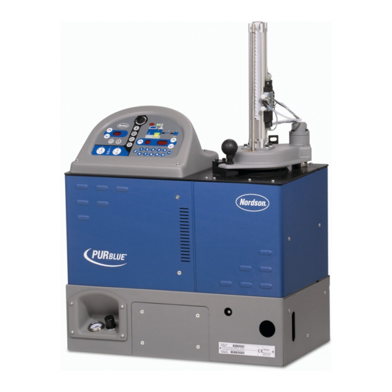
Description Section 2 Description This manual describes the installation and use of PURBlue 4 high-output adhesive melters. When necessary, the reader is referred to the documentation supplied with other Nordson products or products supplied by third parties. Figure 2-1 PURBlue 4 high-output adhesive melter... -
Page 22: Other Sources Of Information
Other Sources of Information Refer to the following additional resources for quick-reference information, technical support, and information about getting the most out of your PURBlue 4 high-output melter. Online Support Visit www.enordson.com/support to download melter firmware updates and Blue Series software utilities. -
Page 23: Product Description
Product Description See Figure 2-2. Nordson PURBlue 4 high-output adhesive melters are used in conjunction with Nordson hot melt hoses and guns to create a hot melt application system. The melter liquifies solid-form hot melt in foil wrapped slugs and maintains the hot melt at the desired temperature. -
Page 24: Intended Use
Be used in non-explosive environments Limitations of Use Use PURBlue 4 high-output melters only for the purpose for which they are designed. PURBlue 4 melters should not be used: to melt or pump any material that creates a health or safety hazard... -
Page 25: Modes Of Operation
Description Modes of Operation PURBlue 4 high-output melters operate in the following modes: Automatic scan — The melter automatically checks and displays the current temperature of the reservoir, hoses, and guns to confirm that they are within their pre-defined temperature range. By default, the melter is always in the automatic scan mode unless it is placed into another operating mode. -
Page 26: Pressure Control Options
Description Pressure Control Options PURBlue 4 high-output melters have two different pressure control options for maintaining maximum adhesive output pressure. When the melter is dispensing adhesive, the system hydraulic pressure is governed by the pressure drop through the manifold, hose, and applicator as affected by fluid flow rate, fluid viscosity, and nozzle size(s). - Page 27 Description This page intentionally left blank. Part 1120277_01 E 2012 Nordson Corporation...
-
Page 28: Key Components
8. Drive removal jack screw 12. Switch receptacles 5. Hopper, melt plate, and reservoir 9. Drive cover or optional pressure assembly (cover removed for clarity) control drive cover (F option drive cover not shown) Part 1120277_01 E 2012 Nordson Corporation... - Page 29 11. Clock key/LED 18. Hopper empty LED 5. Keypad 12. Setup key/LED 19. Piston down key/LED 6. Left display and scroll key 13. Clear/reset key 7. Service LED 14. Pump speed display (rpms) and arrow keys Part 1120277_01 E 2012 Nordson Corporation...
-
Page 30: Optional Equipment
Optional Equipment Optional equipment may be ordered to expand the functionality of PURBlue 4 melters, including, but not limited to, the following: Automatic pressure control option kits that allow the melter to automatically adjust adhesive output pressure based on production requirements. -
Page 31: Installation
Overview PURBlue 4 melters are factory-configured for each order and require only the assembly and set up tasks described in this section. The melter is shipped from the factory with an installation kit that contains components that must be assembled on the melter by the customer. -
Page 32: Installation Tasks
The instructions provided in this section are intended to be used by personnel who have experience in the following subjects: Hot melt application processes Industrial power and control wiring Industrial mechanical installation practices Basic process control and instrumentation Part 1120277_01 E 2012 Nordson Corporation... - Page 33 Installation This page intentionally left blank. Part 1120277_01 E 2012 Nordson Corporation...
-
Page 34: Installation Requirements
290 mm (11.4 in.) remove the service cover Depth of melter including service 678 mm (26.7 in.) handles Minimum vertical space required for the 964 mm (37.9 in.) melter if mounting feet are not used Part 1120277_01 E 2012 Nordson Corporation... - Page 35 Installation Figure 3-1 Minimum installation clearances Part 1120277_01 E 2012 Nordson Corporation...
-
Page 36: Electrical Power
Nordson recommends that an isolation valve be installed in the plant air supply line just before the melter. -
Page 37: Other Considerations
The melter must be installed where it will be in conformance with the ventilation requirements specified in the Material Safety Data Sheet for the hot melt being used. Part 1120277_01 E 2012 Nordson Corporation... -
Page 38: Unpacking The Melter
Before starting the installation, remove the melter from the pallet, locate the installation kit, and inspect the melter for damaged and missing parts. Report any problems to your Nordson representative. Customer-Supplied Materials The following additional materials are required to install the melter:... - Page 39 Installation kit components 1. Voltage plug (2) 4. Spare fuses (8) 7. Strain relief connector (1) 2. Voltage plug with neutral (2) 5. Straight hose fitting (1) 3. Input/output connectors (2) 6. 90-degree hose fitting (1) Part 1120277_01 E 2012 Nordson Corporation...
-
Page 40: Mounting The Melter
12.7 10.3 15.0 4X M6X1.0 - 6H THRU ALL FOR MOUNTING FEET (NOT SHOWN) 4X M10X1.5 - 6H THRU ALL ATTACHING BOLT THREAD ENGAGEMENT MIN 10MM / MAX 30MM Figure 3-3 Bolt mounting pattern Part 1120277_01 E 2012 Nordson Corporation... -
Page 41: Configuring The Electrical Service
3-11 Configuring the Electrical Service PURBlue 4 melters are shipped from the factory without an attached power cable and without a designated service-type. To configure the melter to function in your facility, you must connect a power cable to the melter and designate the service type by installing a Nordson-supplied voltage plug into the melter. - Page 42 The ground lug is marked PE/G. Opening the electrical enclosure EXAMPLE ONLY (3/N/PE AC wiring shown) L1 L2 L3 N PE/G Figure 3-4 Connecting the power cable and ground lead Part 1120277_01 E 2012 Nordson Corporation...
- Page 43 NOTE A: The 400/230 VAC 3-phase service (4-wire service including neutral) includes the 415/240 VAC 3-phase (4-wire service, including neutral) voltage. The 230 VAC 1-phase service (2-wire service, including a neutral) includes the 240 VAC 1-phase (2-wire service, including a neutral) voltage. Part 1120277_01 E 2012 Nordson Corporation...
- Page 44 If the electrical service was configured correctly, the melter control panel (plugs with and without the neutral will display dashes. lead shown) P/N 232617 P/N 227567 P/N 227569 P/N 227568 Figure 3-5 Connecting a voltage plug Part 1120277_01 E 2012 Nordson Corporation...
- Page 45 Installation 3-15 This page intentionally left blank. Part 1120277_01 E 2012 Nordson Corporation...
-
Page 46: Connecting Hoses And Guns
3-16 Connecting Hoses and Guns PURBlue 4 melters use standard Nordson hoses and guns and support the connection of up to three hose/gun pairs. The hose/gun capacity of each melter is determined by the number of hose/gun receptacles on the melter. - Page 47 Connecting a switched handgun hose or footswitch To connect guns Observe the following guidelines: For information about choosing the most appropriate Nordson hot melt gun for your manufacturing process, refer to the latest edition of Nordson's hot melt dispensing equipment Replacement Parts Catalog or contact your Nordson representative.
-
Page 48: Connecting A Compressed Air Supply
3. Turn the air regulator (1) to set the melter's operating air pressure (pressure supplied to the piston) to 2 bar (30 PSI). 2 (6 mm) Figure 3-7 Location of the air supply input port 1. Piston air regulator and gauge 2. Air supply inlet Part 1120277_01 E 2012 Nordson Corporation... -
Page 49: Connecting A Pressure Control Signal
Figure 3-8 Connecting a signal to the pressure control terminal block for the pressure control F option 1. Pressure control option terminal block 2. F Option drive cover assembly 3. Pneumatic PCV Part 1120277_01 E 2012 Nordson Corporation... -
Page 50: Setting Up The Melter
If you need to make changes to the factory setup or if you want to learn about other operating parameters, go to the next part in this section, Operating Parameters. Part 1120277_01 E 2012 Nordson Corporation... - Page 51 A group of parameters that control the melter's clock. 50 to 77 Seven-day Clock The clock is used to automatically turn the heaters on Disabled and off and to place the melter into the standby mode. Part 1120277_01 E 2012 Nordson Corporation...
-
Page 52: Operating Parameters
In addition to the ability to read and edit parameter values, you can also save and restore the current value of every operating parameter and review a log of the last ten changes that were made to editable parameters. Part 1120277_01 E 2012 Nordson Corporation... -
Page 53: Selecting Operating Parameters
NOTE: Motor control parameters are set differently from operating parameters. Refer to Setting up the Motor Control later in this section. Some applications will require a change to one or more motor control parameters. Part 1120277_01 E 2012 Nordson Corporation... -
Page 54: Reading Or Editing Operating Parameters
NOTE: If the keypad has no affect on the right display, the melter is password protected. You must enter a valid password before you can edit parameters. Refer to Entering the Melter Password in Section 4, Operation. Part 1120277_01 E 2012 Nordson Corporation... - Page 55 Change Hose 1 Output to Electric Gun 0 (disabled) or 1 (enabled) 0 (disabled) Activation Change Hose 2 Output to Electric Gun 0 (disabled) or 1 (enabled) 0 (disabled) Activation External Communications Lock-out 0 or 1 0 (disabled) Continued... Part 1120277_01 E 2012 Nordson Corporation...
- Page 56 6 (Alert) Optional Output 4 0–6 0 (disabled) Optional Output 5 0–6 0 (disabled) Optional Output 6 0–6 0 (disabled) Optional Output 7 0–6 0 (disabled) PUR Timer PUR timer 10-120 minutes 30 minutes Continued... Part 1120277_01 E 2012 Nordson Corporation...
- Page 57 NOTE: Motor control parameters are set differently from operating parameters. Refer to Setting Up the Motor Control later in this section. Some applications will require a change to one or more motor control parameters. Part 1120277_01 E 2012 Nordson Corporation...
-
Page 58: Setpoint Temperature Of The Reservoir, Hoses, And Guns
Adjusting Component Temperatures in Section 4, Operation. As with operating parameters, you can also save and restore setpoint temperatures and review past changes that were made to setpoint temperatures. Part 1120277_01 E 2012 Nordson Corporation... - Page 59 Each component begins to heat or cool to the new global setpoint temperature and the melter returns to the automatic scan mode. Reservoir key When all of the components reach the global setpoint temperature, the ready LED turns on (green). Ready LED Part 1120277_01 E 2012 Nordson Corporation...
-
Page 60: Save And Restore Melter Settings
With the melter in the automatic scan mode, simultaneously press the number 2 key and the Setup key. S-2 appears momentarily in the right display. Restoring current settings Part 1120277_01 E 2012 Nordson Corporation... - Page 61 Installation 3-31 This page intentionally left blank. Part 1120277_01 E 2012 Nordson Corporation...
-
Page 62: Review Parameter And Setpoint Temperature Changes
3. Press a right-display scroll key to review each of the remaining nine log entries. Each press of a scroll key displays a progressively older log entry. 4. Press the Setup key to return to the automatic scan mode. Scrolling through the fault log Part 1120277_01 E 2012 Nordson Corporation... - Page 63 Parameter 4 (ready delay) was changed. Example 2: If the LED on the gun key is on, then this display would indicate that the global-by-component method was used to change the temperature of the guns. Part 1120277_01 E 2012 Nordson Corporation...
-
Page 64: Installing Melter Inputs
Installation 3-34 Installing Melter Inputs PURBlue 4 melters are equipped with two standard digital inputs. Each input is customer-wired to the melter and then set up to provide one of the following control options: Place the melter into the standby mode... - Page 65 3. Plug the connector (P/N 277909) into the bottom receptacle of terminal Connector P/N 277909 XT7, which is located on the expansion board. If input number four is used, plug connector P/N 277908 into the top receptacle on terminal XT7. Figure 3-9 Wiring inputs Part 1120277_01 E 2012 Nordson Corporation...
- Page 66 The input capacity of the melter may be Section 7, Parts increased from four inputs to a total of ten inputs by adding an optional I/O expansion card that is available from Nordson Corporation. Part 1120277_01 E 2012 Nordson Corporation...
- Page 67 I/O board is installed. Refer to Appendix B, Operating Parameters, for more information. C: Refer to the instruction sheet provided with the optional I/O expansion card or analog I/O board for wiring information. Part 1120277_01 E 2012 Nordson Corporation...
-
Page 68: Installing Melter Outputs
Installation 3-38 Installing Melter Outputs The PURBlue 4 melter is equipped with three user-configurable digital outputs. Outputs are used to communicate with user-supplied production equipment or control hardware, such as a programmable logic controller. Each output is customer-wired and then set up in the melter's firmware to... - Page 69 Set up the parameter control option for each output that you connected to the melter. Table 3-9 lists the available control options. Refer to Setting Up the Melter earlier in this section for information about how to select operating parameters and edit parameter control options. Part 1120277_01 E 2012 Nordson Corporation...
- Page 70 C: For PURBlue 4 melters, a reservoir-empty state produces a melter fault after several seconds. When the fault occurs, the reservoir-empty output reverts back to its standard condition. In most cases, Nordson Corporation recommends the use of control option 3 (Fault), which will indicate a reservoir-empty state or any other condition that will stop production.
- Page 71 Installation 3-41 This page intentionally left blank. Part 1120277_01 E 2012 Nordson Corporation...
-
Page 72: Setting Up Gear-To-Line Operation
See Figure 3-11. Opening the electrical enclosure 2. Connect a 0-10 VDC line speed reference signal to terminals A8-X5-1 (+) and A8-X5-2 (-) on the motor control assembly. Part 1120277_01 E 2012 Nordson Corporation... - Page 73 Installation 3-43 A8-X5-1 (+) A8-X5-2 (- -) Figure 3-11 Connecting a line speed reference signal for gear-to-line operation Part 1120277_01 E 2012 Nordson Corporation...
-
Page 74: Setting Up The Motor Control
5. Repeat steps 3-4 for each parameter you want to change. 6. To exit the setup mode, press the Pump mode key one additional time after the last parameter has been displayed. Pump mode key Part 1120277_01 E 2012 Nordson Corporation... - Page 75 After the set number of turns, the melter will shut down and display an F9/1 melter fault code. Refer to Melter Faults in Section 6, Troubleshooting, for more information on melter fault codes. Part 1120277_01 E 2012 Nordson Corporation...
-
Page 76: Installing Optional Equipment
Flushing the Melter Flush the melter before initial operation. Refer to Flushing the Melter in Section 5, Maintenance. Refer to Section 4, Operation, for information about filling the hopper and operating the melter. Part 1120277_01 E 2012 Nordson Corporation... - Page 77 Most of the controls described in this section are located on the control panel. Refer to Key Components in Section 2, Description, for the location of the controls and indicators described in this section. Part 1120277_01 E 2012 Nordson Corporation...
-
Page 78: Operation
If the slug is not changed and the four minute time limit is exceeded, the melt plate will turn off. The actual temperature of the melt plate can be displayed by pressing the Reservoir key and then 2. Part 1120277_01 E 2012 Nordson Corporation... -
Page 79: Loading An Adhesive Slug
Operation Loading an Adhesive Slug The PURBlue 4 melter is designed to work with PUR adhesive slugs in sealed foil bags. Before loading an adhesive slug, confirm that the hot melt material is compatible with the melter. Refer to Intended Use in Section 2, Description, for information about hot melt materials that should not be used in PURBlue 4 melters. - Page 80 (PIP) over the hopper. If the piston is in place, it applies downward force for 30 seconds after the Piston down key is pressed. After 30 seconds, the downward force is turned on and off by the Piston down key melt-on-demand sensor functionality. Part 1120277_01 E 2012 Nordson Corporation...
-
Page 81: Starting The Melter
3 _C (5 _F) of their assigned setpoint temperature. NOTE: If the Ready Delay Time (parameter 4) is set to a value other than 0, then this additional time must pass before the ready state will be reached. Part 1120277_01 E 2012 Nordson Corporation... -
Page 82: Operating In Manual Mode
NOTE: When the melter is operating in the manual mode, the pump speed is determined by the following equation. Refer to Section 8, Technical Data, for pump displacement values. Adhesive output = displayed rpm × pump displacement (cc/min) Part 1120277_01 E 2012 Nordson Corporation... -
Page 83: Operating In Gear-To-Line Mode
NOTE: When the melter is operating in the gear-to-line mode, the pump speed is determined by the following equation. Refer to Section 8, Technical Data, for pump displacement values. Adhesive input voltage output = displayed rpm × pump displacement × (cc/min) Part 1120277_01 E 2012 Nordson Corporation... -
Page 84: Adjusting The Pcv
With the melter at operating temperature, the line running, and the guns dispensing adhesive, turn the adjustment screw on the PCV: clockwise to increase the adhesive output counterclockwise to decrease the adhesive output Adjusting the PCV Part 1120277_01 E 2012 Nordson Corporation... -
Page 85: Flow Control Bypass (F Option)
1. Press the Standby key to reduce the system temperature and place the system in standby mode. 2. Cover the applicator nozzles with petroleum jelly or submerge them in a suitable oil. Standby key Part 1120277_01 E 2012 Nordson Corporation... -
Page 86: Monitoring The Melter
Refer to Monitor Melter Faults and Using Melter Function Keys later in this section for information about melter faults and using the seven-day clock and standby functions. Refer to Appendix B, parameter 4, for information about the ready delay. Part 1120277_01 E 2012 Nordson Corporation... -
Page 87: Monitor The Adhesive Level
The melter is shipped with both level sensors calibrated for standard adhesive. If recalibration becomes necessary, refer to Calibrating the Hopper-Empty Sensor or Calibrating the Level Sensors in Section 5, Maintenance. Figure 4-2 Location of the level sensors 1. Melt-on-demand sensor 2. Reservoir-empty monitor Part 1120277_01 E 2012 Nordson Corporation... -
Page 88: Monitor Component Temperatures
3. When the position number of the desired component appears in the left display, observe the right display to determine the component's actual temperature. NOTE: On PURBlue 4 melters, 1 is the pump temperature and 2 is the Component keys melt plate temperature when the reservoir LED is on. - Page 89 (blank display). Left display and scroll key NOTE: On PURBlue 4 melters, 1 is the pump temperature and 2 is the melt plate temperature when the reservoir LED is on. 2. If the first sequential component is not the component you want to check, use the left-display scroll key to change to the correct component number.
-
Page 90: Monitor Melter Faults
RAM backup Clock does not Insufficient voltage from Replace CPU F4/3 battery function RAM backup battery Internal clock Heaters remain on, Battery-backed RAM Replace CPU F4/4 battery backed but fault condition failure persists Continued... Part 1120277_01 E 2012 Nordson Corporation... - Page 91 CPU and the card persists optional I/O card Alert output (if output Fieldbus option 6 is selected) Replace the Fieldbus F4/E communications Fieldbus card failure Melter continues to card failure operate normally. Continued... Part 1120277_01 E 2012 Nordson Corporation...
- Page 92 B: For a detailed description of how the melt-on-demand functionality of this melter works, refer to Modes of Operation in Section 2, Description. Part 1120277_01 E 2012 Nordson Corporation...
-
Page 93: How F1, F2, And F3 Faults Are Handled
LED will turn off, the red fault LED will turn on, the heaters turn off, and the melter records the fault in the fault log. Refer to To review the fault log later in this section. Fault LED Part 1120277_01 E 2012 Nordson Corporation... -
Page 94: How F4 Faults Are Handled
I/Os. Refer to Section 6, Troubleshooting, for information about diagnosing F4 faults. 5. The melter records the fault in the fault log. Refer to To review the fault log later in this section. Part 1120277_01 E 2012 Nordson Corporation... - Page 95 2. Return the melter to the automatic scan mode by pressing the Setup key twice. Setup key 3. Press the Clear/reset key. Clear/reset key 4. Press the Heaters key to turn on the heaters. Heaters key Part 1120277_01 E 2012 Nordson Corporation...
- Page 96 Scrolling through 4. Press the Setup key to return to the automatic scan mode. the fault log Part 1120277_01 E 2012 Nordson Corporation...
-
Page 97: Monitor Motor/Piston Control Or Motor Drive Faults
The pump speed display and the display on the motor drive located inside the electrical enclosure alert the operator to abnormal motor/piston-related faults. These faults may cause the pump to stop. Refer to Motor/Piston Control Faults or Motor Drive Faults in Section 6, Troubleshooting. Part 1120277_01 E 2012 Nordson Corporation... -
Page 98: Monitor The Service Interval
Service LED To reset the service LED With the melter in the scan mode, press the Clear/Reset key to turn off the service LED and reset the service interval time. Clear/reset key Part 1120277_01 E 2012 Nordson Corporation... -
Page 99: Adjusting Component Temperatures
The right display indicates all dashes (----) and the LEDs on all of the component keys turn green. Left display and scroll key 3. Press the Enter key. The right display flashes. Enter key Part 1120277_01 E 2012 Nordson Corporation... - Page 100 5. Press the Reservoir key. All components begin to heat or cool to the new global setpoint temperature. When all of the components reach their setpoint temperature, the ready LED turns on (green). Reservoir key Part 1120277_01 E 2012 Nordson Corporation...
- Page 101 Refer to Entering the Melter Password later in this section. 5. Press the Enter key. The hoses or the guns begin to heat or cool to their new setpoint temperature. Part 1120277_01 E 2012 Nordson Corporation...
- Page 102 To register the new setpoint temperature and return to the automatic scan mode, go to step 6. 6. Press any component key (reservoir, hose, or gun). The selected component begins to heat or cool to its new setpoint temperature. Part 1120277_01 E 2012 Nordson Corporation...
-
Page 103: Entering The Melter Password
If the password is incorrect, the left display remains at 0 and the right display momentarily indicates dashes (----) and then returns to 4000. If the password is incorrect, re-enter it and then press the Enter key. Part 1120277_01 E 2012 Nordson Corporation... -
Page 104: Using Melter Function Keys
When a fault occurs (refer to Monitor Melter Faults earlier in this section) the Heaters key heaters automatically turn off. The heaters key is used to turn the heaters back on after correcting a fault condition. Part 1120277_01 E 2012 Nordson Corporation... -
Page 105: Pump Enable Key
The LED on the pump mode key is green when the melter is in the manual mode. When the melter is operating in the gear-to-line mode, a 0-10 VDC signal must be supplied. Refer to Setting Up Gear-to-Line Operation in Section 3, Pump mode key Installation. Part 1120277_01 E 2012 Nordson Corporation... -
Page 106: Setup Key
Refer to Appendix B, Operating Parameters, Seven-day Clock, for information about setting up the seven-day clock and the standby delta. Part 1120277_01 E 2012 Nordson Corporation... -
Page 107: Standby Key
Using the standby key overrides the control of the melter (on or off) by the seven-day clock or a remote input. Refer to Section 3, Installation, Setting Up the Melter, and to Appendix B, Operating Parameters, for information about setting the standby delta and the standby timer. Part 1120277_01 E 2012 Nordson Corporation... -
Page 108: Shutting Down The Melter
Ensure that material connections are closed such that they are airtight. 4. If the system will be shut down for a longer period of time, rinse it with a suitable cleaning agent. Use only a cleaning agent recommended by the material manufacturer. Part 1120277_01 E 2012 Nordson Corporation... -
Page 109: Maintenance
Preventive Maintenance Tasks Table 5-1 describes the preventive maintenance tasks required to keep PURBlue 4 melters operating within their specified limits and to prevent equipment malfunctions. For information about maintaining optional equipment that was supplied by Nordson, refer to the instructions provided with the equipment. - Page 110 (sensors are Sensor or Calibrating the Level factory-calibrated) Sensors Calibrating the pump speed display As needed throughout the life of the Calibrating the Pump Speed Display melter (the pump speed display is factory-calibrated) Part 1120277_01 E 2012 Nordson Corporation...
-
Page 111: Relieving System Pressure
2. Set the control option for parameter 14 to 1 (enabled). 3. When the service activity is complete, return parameter 14 to 0 (disabled). Pump mode key Refer to Setting Up the Melter in Section 3, Installation, for information about changing operating parameters. Part 1120277_01 E 2012 Nordson Corporation... -
Page 112: Flushing The Melter
Process a minimum of one reservoir volume of hot melt or flushing material through the melter, hoses, and applicators. At some point, set the pressure control to a low value and close the applicator(s) to flush the pressure control recirculation loop. Part 1120277_01 E 2012 Nordson Corporation... -
Page 113: Cleaning The Melter
5. Reverse steps 2-4 to reinstall each cover. To clean the electrical enclosure After covers are removed, inspect the fan area and ensure that the air flow path for both side covers is clear. Remove excessive dust from inside the cabinet. Part 1120277_01 E 2012 Nordson Corporation... - Page 114 Maintenance Cleaning the Melter (contd) Figure 5-1 Removing the service covers 1. Hopper cover 2. Service cover 3. Manifold cover Part 1120277_01 E 2012 Nordson Corporation...
-
Page 115: Cleaning The Hopper And Melt Plate
This surface must be clear so that a good seal with the adhesive slug foil bag is possible. 4. Restore the system to normal operation. Part 1120277_01 E 2012 Nordson Corporation... -
Page 116: Cleaning The Reservoir And Level Sensors
9. See Figure 5-2. Clean the melt demand and reservoir empty sensor probes at the back of the reservoir. 10. Restore the system to normal operation. Part 1120277_01 E 2012 Nordson Corporation... - Page 117 Maintenance Figure 5-2 Hopper/melt plate assembly removal and the location of the level sensor probes Part 1120277_01 E 2012 Nordson Corporation...
-
Page 118: Cleaning The Piston
10. If the adhesive is cool, try to peel it from the release-coated parts. If the adhesive is hot, use a wooden or plastic scraper to remove it. 11. Restore the system to normal operation. Piston down key Part 1120277_01 E 2012 Nordson Corporation... -
Page 119: Calibrating The Hopper-Empty Sensor
2. Loosen the hopper-empty sensor (1) and move it to the lowest position on the piston (2). 3. Move the sensor up until its LED illuminates and then secure the sensor at this location. Figure 5-3 Location of the hopper-empty sensor 1. Hopper-empty sensor 2. Piston Part 1120277_01 E 2012 Nordson Corporation... -
Page 120: Calibrating The Level Sensors
NOTE: When an LED turns yellow, the system believes that adhesive is present. Because we know that adhesive is not present, turning an adjustment screw counterclockwise until the LED turns green and then adding an additional two (2) counterclockwise turns calibrates the sensors. Part 1120277_01 E 2012 Nordson Corporation... - Page 121 Green Amber Figure 5-4 Location of the level sensor adjustment screws and LEDs 1. Melt-on-demand sensor (S1) 3. Level sensor LED 4. Level sensor adjustment screw (behind plug) 2. Reservoir-empty monitor Part 1120277_01 E 2012 Nordson Corporation...
-
Page 122: Calibrating The Pump Speed Display
2. Press and hold both Pump speed arrow keys. 3. When the motor control display indicates CAL, release the keys. Pump speed display and arrow keys 4. Enter the actual pump rpm. 5. Press the Pump mode key. Pump mode key Part 1120277_01 E 2012 Nordson Corporation... -
Page 123: Troubleshooting
If you cannot resolve the problem using the troubleshooting flowchart, contact your Nordson representative for technical assistance. Safety Never disconnect cables from, or reconnect cables to, any circuit board while the melter is energized. -
Page 124: Melter Faults
RAM backup Clock does not Insufficient voltage from Replace CPU F4/3 battery function RAM backup battery Internal clock Heaters remain on, Battery-backed RAM Replace CPU F4/4 battery backed but fault condition failure persists Continued... Part 1120277_01 E 2012 Nordson Corporation... - Page 125 CPU and the card persists optional I/O card Alert output (if output Fieldbus option 6 is selected) Replace the Fieldbus F4/E communications Fieldbus card failure Melter continues to card failure operate normally. Continued... Part 1120277_01 E 2012 Nordson Corporation...
- Page 126 B: For a detailed description of how the melt-on-demand functionality of this melter works, refer to Modes of Operation in Section 2, Description. Part 1120277_01 E 2012 Nordson Corporation...
-
Page 127: Motor/Piston Control Faults
Close the lid. (Lid Not Closed) Displayed rpms do not Pump speed display not Calibrate the pump speed match motor speed calibrated display. Refer to Calibrating the Pump Speed Display in Section 5, Maintenance. Continued... Part 1120277_01 E 2012 Nordson Corporation... - Page 128 Allow the temperature to stabilize for 30 minutes (with the maximum air pressure still applied). Part 1120277_01 E 2012 Nordson Corporation...
-
Page 129: Motor Drive Faults
1. Motor drive power LED (steady=OK, 2. Display flashing=fault, off=no power) Note: Do not use the motor drive keys. Contact your Nordson representative for assistance if you need to adjust any motor drive settings. Part 1120277_01 E 2012 Nordson Corporation... - Page 130 Ensure that the unit ambient temperature does not exceed 50 _C (120 _F), that the electrical enclosure vents are not blocked, and that the electrical enclosure fan is operating properly. Continued... Part 1120277_01 E 2012 Nordson Corporation...
- Page 131 Section 8, Technical Data, for allowable input Overvoltage Disturbed line supply voltage range. Motor drive parameter(s) changed Contact your Nordson representative. Configuration fault Check the unit input line voltage. Refer to Line supply too low Section 8, Technical Data, for allowable input...
-
Page 132: Pump Operational Status
Ready status of the melter Activation of a switched input (handgun or footswitch) Activation of the pump key Table 6-4 provides the status of the pump LED for each combination of the pump operating variables. Part 1120277_01 E 2012 Nordson Corporation... - Page 133 B: If the remote motor input is assigned, then its status is described in this column. C: “On” means the pump key was pressed and the unit accepted the key press. “ ” means that the Ignored pump key will not respond to a key press. Part 1120277_01 E 2012 Nordson Corporation...
-
Page 134: Using The Troubleshooting Flow Chart
Use of the chart assumes that the melter is installed correctly and that it is set up to support the current manufacturing process. Refer to Section 3, Installation, for information about installing and setting up the melter. Troubleshooting question and action blocks a) Question b) Action Part 1120277_01 E 2012 Nordson Corporation... -
Page 135: Troubleshooting Quick-Checks
Reservoir and Clear/reset keys, and then switch the melter back on, holding the Reservoir and Clear/reset keys until the letters PUR appear on the right display. This will reset the melter as a PUR melter. Part 1120277_01 E 2012 Nordson Corporation... -
Page 136: Identifying Electrical Components
Melt plate heaters (6.3 A, 250 V, 5 x 20 mm) F9/F10 Hose/gun 1 heaters (6.3 A, 250 V, 5 x 20 mm) F11/F12 Motor start (6.3 A, 250 V, 5 x 20 mm) Continued... Part 1120277_01 E 2012 Nordson Corporation... - Page 137 Input voltage configuration plugs Input 24 VDC in from main board Input/output Ribbon cable connection between expansion board and power module (hoses/guns 2 and 3) Input/output Ribbon cable connection between expansion board and main board Part 1120277_01 E 2012 Nordson Corporation...
- Page 138 Connection point for the wire harness between hose/gun 2 and the power module J4/J5 Input AC power input from XT2 on the expansion board Fuses F1, F2 Hose 3 and gun 3 F3, F4 Hose 2 and gun 2 Part 1120277_01 E 2012 Nordson Corporation...
- Page 139 Sensor input Piston-in-place sensor connection Sensor input Melt on demand sensor connection Sensor input Reservoir empty sensor connection Sensor input Hopper empty sensor connection Switch Switch to put motor control CPU into software upgrade mode Part 1120277_01 E 2012 Nordson Corporation...
- Page 140 Test Test Test Test Output Solenoid 1 Output Solenoid 2 Fuses Fuse Fuse for fan, motor drive, 24VDC power supply Fuse Same as above Fuse Fuse for 24 VDC power to and through board Part 1120277_01 E 2012 Nordson Corporation...
- Page 141 Troubleshooting 6-19 Part 1120277_01 E 2012 Nordson Corporation...
- Page 142 Troubleshooting 6-20 Part 1120277_01 E 2012 Nordson Corporation...
- Page 143 Troubleshooting 6-21 Part 1120277_01 E 2012 Nordson Corporation...
- Page 144 Troubleshooting 6-22 Part 1120277_01 E 2012 Nordson Corporation...
- Page 145 Troubleshooting 6-23 Part 1120277_01 E 2012 Nordson Corporation...
- Page 146 Troubleshooting 6-24 Part 1120277_01 E 2012 Nordson Corporation...
- Page 147 Troubleshooting 6-25 Part 1120277_01 E 2012 Nordson Corporation...
- Page 148 Troubleshooting 6-26 Part 1120277_01 E 2012 Nordson Corporation...
- Page 149 Troubleshooting 6-27 Part 1120277_01 E 2012 Nordson Corporation...
- Page 150 Troubleshooting 6-28 Part 1120277_01 E 2012 Nordson Corporation...
- Page 151 Troubleshooting 6-29 Part 1120277_01 E 2012 Nordson Corporation...
- Page 152 Troubleshooting 6-30 Part 1120277_01 E 2012 Nordson Corporation...
- Page 153 Troubleshooting 6-31 Part 1120277_01 E 2012 Nordson Corporation...
- Page 154 Troubleshooting 6-32 Part 1120277_01 E 2012 Nordson Corporation...
- Page 155 Troubleshooting 6-33 Part 1120277_01 E 2012 Nordson Corporation...
- Page 156 Troubleshooting 6-34 Part 1120277_01 E 2012 Nordson Corporation...
- Page 157 Troubleshooting 6-35 Part 1120277_01 E 2012 Nordson Corporation...
- Page 158 Troubleshooting 6-36 Part 1120277_01 E 2012 Nordson Corporation...
- Page 159 Troubleshooting 6-37 Part 1120277_01 E 2012 Nordson Corporation...
- Page 160 Troubleshooting 6-38 Part 1120277_01 E 2012 Nordson Corporation...
- Page 161 Troubleshooting 6-39 Part 1120277_01 E 2012 Nordson Corporation...
- Page 162 Troubleshooting 6-40 Part 1120277_01 E 2012 Nordson Corporation...
- Page 163 Troubleshooting 6-41 Part 1120277_01 E 2012 Nordson Corporation...
- Page 164 Troubleshooting 6-42 Part 1120277_01 E 2012 Nordson Corporation...
- Page 165 Troubleshooting 6-43 Part 1120277_01 E 2012 Nordson Corporation...
- Page 166 Troubleshooting 6-44 Part 1120277_01 E 2012 Nordson Corporation...
- Page 167 Troubleshooting 6-45 Part 1120277_01 E 2012 Nordson Corporation...
- Page 168 Troubleshooting 6-46 Part 1120277_01 E 2012 Nordson Corporation...
- Page 169 Troubleshooting 6-47 Part 1120277_01 E 2012 Nordson Corporation...
- Page 170 Troubleshooting 6-48 Part 1120277_01 E 2012 Nordson Corporation...
- Page 171 Troubleshooting 6-49 Part 1120277_01 E 2012 Nordson Corporation...
- Page 172 Troubleshooting 6-50 Part 1120277_01 E 2012 Nordson Corporation...
- Page 173 Troubleshooting 6-51 Refer to PURBlue 4 Troubleshooting Chart T.4.2. Figure 6-2 Opening the reservoir isolation valve 1. Open 2. Closed Part 1120277_01 E 2012 Nordson Corporation...
- Page 174 Troubleshooting 6-52 Part 1120277_01 E 2012 Nordson Corporation...
-
Page 175: Parts
Section 7 Parts Using the Illustrated Parts Lists To order parts, call the Nordson Customer Service Center or your local Nordson representative. Use these five-column parts lists, and the accompanying illustrations, to describe and locate parts correctly. The following chart provides guidance for reading the parts lists. - Page 176 Parts This page intentionally left blank. Part 1120277_01 E 2012 Nordson Corporation...
-
Page 177: Melter Part Numbers
NOTE: The following table is not a complete list of melter configurations. As new configurations are ordered, additional melter part numbers will be created. Contact your Nordson representative for information on configuring a PURBlue 4 high-output melter. Part Number... -
Page 178: Top Support Plate Assembly Parts
S SHIELD, DOOR, ELEC, PB4 - - - - - - S SHIELD, PANEL, REAR, PB4 - - - - - - S RIVET, POP, 1/8X.250 CARBON STL 288221 S GASKET, .354X.216, MPL, 3000V (cut pcs) Part 1120277_01 E 2012 Nordson Corporation... - Page 179 Parts Figure 7-2 Top support plate assembly parts Part 1120277_01 E 2012 Nordson Corporation...
-
Page 180: Hopper/Melt Plate Assembly Parts
- - - - - - S CABLETIE,4 IN,338F/170C,BLUE 1120261 KIT,SERVICE,GRID HEATER ASSY,240V,PB4, 1096020 KIT,SERVICE,MAN./GRID,RTD SENSOR, PB4 NOTE A: Refer to Heaters and RTDs (Sensors) later in this section for an illustration of the heater/RTD locations. NS: Not Shown Part 1120277_01 E 2012 Nordson Corporation... - Page 181 Parts (4X 1088036A) Figure 7-3 Hopper/grid assembly parts Part 1120277_01 E 2012 Nordson Corporation...
-
Page 182: Reservoir Assembly Parts
KIT,SERVICE,RESERVOIR, RTD SENSOR, PB4 NOTE A: To replace this part, order service kit 1095999. B: Refer to Heaters and RTDs (Sensors) later in this section for an illustration of the heater/RTD locations. NS: Not Shown Part 1120277_01 E 2012 Nordson Corporation... - Page 183 Parts 2 x 9 2 x 11 (16) Section B--B Section A--A Figure 7-4 Reservoir assembly parts Part 1120277_01 E 2012 Nordson Corporation...
-
Page 184: Pivot Lid Assembly Parts
- - - - - - S TUBING, 6 MM ODX 1 MM WALL 900344 S LUBRICANT, NEVER SEEZ, 8OZ CAN NOTE A: To replace these parts, order service kit 1093148. This kit includes item 12. NS: Not Shown Part 1120277_01 E 2012 Nordson Corporation... - Page 185 Parts 7-11 Figure 7-5 Pivot lid assembly parts Part 1120277_01 E 2012 Nordson Corporation...
- Page 186 Parts 7-12 This page intentionally left blank. Part 1120277_01 E 2012 Nordson Corporation...
-
Page 187: Pump/Drive/Manifold Assembly Parts
- - - - - - MODULE, PUMP MANIFOLD DRIVE — - - - - - - S DRIVE ASSY NOTE A: Refer to Drive Assembly later in this section. Figure 7-6 Pump/manifold/drive assembly parts Part 1120277_01 E 2012 Nordson Corporation... -
Page 188: Drive Assembly
S SCR, SKT, M5X10, BL - - - - - - S BRACKET, MANIFOLD COVER, PB4 NOTE A: To replace the motor, order service kit 1093143. B: Refer to Pump/Manifold Assembly later in this section. Part 1120277_01 E 2012 Nordson Corporation... - Page 189 Parts 7-15 2X TORQUE TO 54--60 IN--LB 4X TORQUE TO 2X TORQUE TO 7--8 FT--LB 7--8 FT--LB +.030 .030 -- .000 +0.8 SPACE BETWEEN COUPLING JAWS Figure 7-7 Drive assembly parts Part 1120277_01 E 2012 Nordson Corporation...
-
Page 190: Pump/Manifold Assembly
NOTE A: To replace the manifold, order service kit 1093142. B: Refer to Pump Assembly later in this section. C: Refer to Heaters and RTDs (Sensors) later in this section for an illustration of the heater/RTD locations. AR: As Required NS: Not Shown Part 1120277_01 E 2012 Nordson Corporation... - Page 191 Parts 7-17 4X TORQUE TO 16-18 FT-LB 03 17 18 17 18 Figure 7-8 Pump/manifold assembly parts Part 1120277_01 E 2012 Nordson Corporation...
-
Page 192: Pump Assembly
- - - - - - S ASSY BUSHING F.SHAFT SEALING D12,7 7146229 S IN-ASSEMBLY TOOLS 7136915, 7136918, EN/GE NOTE A: This instruction may be obtained from http://emanual.nordson.com, or contact your Nordson representative. NS: Not Shown Part 1120277_01 E 2012 Nordson Corporation... -
Page 193: Pressure Control Option Parts
Manual PCV (X Option) See Figure 7-10. Item Part Description Quantity Note 1031222 S SVCE KIT, DURABLUE, PCV, 1100 PSI NOTE A: Order this kit to change to this pressure control option. Figure 7-10 Manual PCV Part 1120277_01 E 2012 Nordson Corporation... -
Page 194: Flow Control Bypass (F Option)
NOTE A: Order this kit to change to this pressure control option. To use this option, the pneumatic PCV contained in kit part 1034042 must be installed on the melter. Figure 7-11 Pressure control option parts Note: For a pneumatic schematic of the pressure control F option, refer to Section 8, Technical Data. Part 1120277_01 E 2012 Nordson Corporation... - Page 195 Parts 7-21 This page intentionally left blank. Part 1120277_01 E 2012 Nordson Corporation...
-
Page 196: Electrical Component Parts
- - - - - - S STRAP, CABLE,.875DIA NOTE A: To replace this item, order service kit 1093146. B: To replace this item, order service kit 1095998. C: To replace this item order service kit 1101619. Part 1120277_01 E 2012 Nordson Corporation... - Page 197 Parts 7-23 Figure 7-12 Control panel assembly parts Part 1120277_01 E 2012 Nordson Corporation...
-
Page 198: Other Circuit Boards And Electrical Components
(melt-on-demand and reservoir-empty sensor probes) NOTE A: For fuses, refer to the next parts list, Main Board Fuses. B: The location where this item is installed is shown in Figure 7-13. NS: Not Shown Part 1120277_01 E 2012 Nordson Corporation... - Page 199 Parts 7-25 Figure 7-13 Other circuit board and electrical component parts Part 1120277_01 E 2012 Nordson Corporation...
-
Page 200: Main Board Fuses
- - - - - - S FUSE, FAST, 5 A, 250 VAC, 5 X 20 MM, F5-F6 939683 S FUSE, 6.3 A, 250 VAC, 5 X 20 MM, F7-F12 Figure 7-14 Fuse service kit parts Part 1120277_01 E 2012 Nordson Corporation... -
Page 201: Heaters
Parts 7-27 Heaters See Figure 7-15. Item Part Description Quantity Note 1120261 KIT,SERVICE,GRID HEATER ASSY,240V,PB4,HO 1096025 KIT, SERVICE, RES. HEATER ASSY, 240V 1096027 KIT, SERVICE, MAN. HEATER ASSY, 240V Figure 7-15 Heaters Part 1120277_01 E 2012 Nordson Corporation... -
Page 202: Rtds (Sensors)
KIT, SERVICE, MANIFOLD/MELT PLATE, RTD SENSOR - - - - - - PLATE, CAPTURE, RTD, ALTA TT-RM - - - - - - SCR,SKT,M5 x 10,BL 1095999 KIT,SERVICE,RESERVOIR, RTD SENSOR, PB4 Figure 7-16 RTDs (sensors) Part 1120277_01 E 2012 Nordson Corporation... -
Page 203: Thermostat Assembly
Note 1096032 KIT, THERMOSTAT, O.O.R, 350 DEG F, PB4 - - - - - - S SCR, SKT, M4X8, BL 900298 S COMPOUND, HEAT SINK, 5 OZ TUBE, 11281 Figure 7-17 Thermostat assembly parts Part 1120277_01 E 2012 Nordson Corporation... -
Page 204: Recommended Spare Parts
Parts 7-30 Recommended Spare Parts Nordson Corporation recommends stocking these service kits and other components for a complete spare parts inventory. Assembly Part Description Note Top support plate 7100642 PROXIMITY SWITCH SIEN-M12B-PS-K-L Hopper/melt plate 1100759 INSULATOR, 134 ID, ALTA TT-RM... -
Page 205: Optional Equipment
To use the gear-to-line capability of the melter, you must install a device that measures the speed of the production line. The default type of line-speed signal input is 0-10 VDC, although other inputs can be accepted. Nordson Corporation offers the following 0-10 VDC generator. - Page 206 Parts 7-32 Part 1120277_01 E 2012 Nordson Corporation...
-
Page 207: Technical Data
C: For displacement information, refer to Motor and Pump Specifications. Motor and Pump Specifications Item Data Note Viscosity range 45,000 cps Maximum hydraulic pressure 75 bar (1100 psi) PR12M1 pump: 1.86 cc/rev Displacement PR12M2 pump: 3.71 cc/rev Part 1120277_01 E 2012 Nordson Corporation... -
Page 208: Electrical Specifications
240 V 137-160 ohms each Melt plate 4 x 200 240 V 287 ohms each NOTE A: Nominal wattage at 177-204 _C (350-400 _F). B: Measured at room temperature for a previously heated element. Part 1120277_01 E 2012 Nordson Corporation... -
Page 209: Dimensions
Technical Data Dimensions 27.0 11.4 37.9 21.1 15.0 25.0 Figure 8-1 Melter dimensions Part 1120277_01 E 2012 Nordson Corporation... -
Page 210: Conduit Penetration Sizes
Technical Data Conduit Penetration Sizes Figure 8-2 Conduit penetration sizes Part 1120277_01 E 2012 Nordson Corporation... -
Page 211: Wiring Diagram
Technical Data Wiring Diagram Part 1120277_01 E 2012 Nordson Corporation... - Page 212 Technical Data Figure 8-3 Wiring diagram Part 1120277_01 E 2012 Nordson Corporation...
-
Page 213: Flow Control Bypass Pneumatic Schematic
Technical Data Flow Control Bypass Pneumatic Schematic FACTORY SET TO 70 PSI; DO NOT ADJUST. FROM AIR TO PNEUMATIC SUPPLY TO PRESSURE CONTOL MELTER VALVE Figure 8-4 Flow control bypass option pneumatic schematic (F option) Part 1120277_01 E 2012 Nordson Corporation... -
Page 214: Melter Configuration Code
Unit identification plate Table 8-1 Melter Configuration Code Values Description Code Values Identifies the equipment as a PURBLUE 4 = PURBlue 4 melter PURBlue 4 melter Adhesive slug size A = 134 mm diameter (2 kg) Voltage 1 = 240 VAC Delta or 400 VAC Wye E = PR12M1 pump (1.86 cc/rev) -
Page 215: Calculating Melter Power Requirements
Two hose/gun pair maximum—The combined wattage of hose/gun pair 1 or hose/gun pairs 2 and 3 If your Nordson representative has already calculated the hose/gun power requirements and confirmed that the maximum allowable wattages will not be exceeded, then no further calculation is necessary. However, you should... - Page 216 Table A-2, then the configuration or position of the hose/gun pairs must be rearranged, shorter hoses must be used, or lower power guns must be used in order to reduce the power requirement. Part 1120277_01 E 2012 Nordson Corporation...
- Page 217 Table A-2 Maximum Allowable Hose/Gun Wattages Column in Component Maximum Wattage Table A-1 Any single hose or gun 1000 W Any hose/gun pair 1200 W Sum of hose/gun pairs 2 and 3 2000 W Part 1120277_01 E 2012 Nordson Corporation...
- Page 218 Calculating Melter Power Requirements Part 1120277_01 E 2012 Nordson Corporation...
-
Page 219: Operating Parameters
PUR Timer Set the PUR timer Seven-day Clock 50 to 77 Configure the clock feature Automatic Fill Configure the external motor control Timer switch PID Selection 80 to 91 Configure the PID settings Part 1120277_01 E 2012 Nordson Corporation... -
Page 220: Standard
F1, F2, F3, and F4 Use: Use the right-display scroll keys to review the log entries for the last ten faults. Empty log entries are indicated by “_-F0.” Refer to Monitoring the Melter in Section 4, Operation. Part 1120277_01 E 2012 Nordson Corporation... - Page 221 The service LED will turn on after the pre-set time elapses. With the melter in the scan mode, press the Clear/Reset key to turn off the service LED and reset the time. Part 1120277_01 E 2012 Nordson Corporation...
- Page 222 If Automatic Pump On is enabled, the pump will turn on automatically when the melter is ready. NOTE: If Automatic Pump On is disabled (0) while the pump is running, the pump will remain on until the pump key is pressed. Part 1120277_01 E 2012 Nordson Corporation...
- Page 223 0 (disabled) Format: — Use: Use only when a Nordson manifold-mounted electric gun is installed and a switching device is connected to the melter's switch receptacle. Refer to the electric gun manual for information on mounting and using the gun.
- Page 224 0 (disabled) Format: — Use: Use only when a Nordson manifold-mounted electric gun is installed and a switching device is connected to the melter's switch receptacle. Refer to the electric gun manual for information on mounting and using the gun.
-
Page 225: Pressure Control
— Default Value: Format: — Use: This parameter is available only when the optional analog I/O board is installed on the melter. Refer to Section 7, Parts, for the I/O board kit part number. Part 1120277_01 E 2012 Nordson Corporation... -
Page 226: Temperature Control
(F2) occurs. Value: 5 _C (10 _F) to 60 _C (110 _F) Resolution: Default Value: 25 _C (50 _F) Format: — Use: — Part 1120277_01 E 2012 Nordson Corporation... - Page 227 (parameter 24) before the heaters turn off. Value: 0 to 1440 minutes (24 hours) Resolution: 1 minute Default Value: 0 (disabled) Format: — Use: Set parameter 24 (automatic standby timeout) to the desired value before setting parameter 25. Part 1120277_01 E 2012 Nordson Corporation...
- Page 228 The number of degrees by which all heated guns will be decreased when the applicator is placed into the standby mode. Value: 1 _C to 190 _C (1 _F to 350 _F) Resolution: 1 _C 1 _F Default Value: Part 1120277_01 E 2012 Nordson Corporation...
- Page 229 This parameter functions like parameter 23 except when it is set to 0, in which case it reverts to the setting for parameter 23. NOTE: The standby delta does not affect the under temperature delta (parameter 22). Part 1120277_01 E 2012 Nordson Corporation...
- Page 230 Melter internal zones are designated as follows: DuraBlue D10/D16: primary=reservoir; secondary=pump DuraBlue D4L/D10L/D16L: primary=reservoir; secondary=pump AltaBlue TT: primary=reservoir; secondary=pump DuraBlue 25/50/100: primary=melt plate; secondary=reservoir AltaBlue 15/30/50/100: primary=melt plate; secondary=reservoir DuraDrum: primary=platen; secondary=pump PURBlue: 4 primary=reservoir; secondary=manifold; tertiary=melt plate Part 1120277_01 E 2012 Nordson Corporation...
-
Page 231: Input Setup
Allows a PUR melter to identify when the hopper is empty. Standard Input 3 (Noneditable) Description: Control option that allows the unit to function as a PUR melter. Value: 19 - Melt demand Resolution: — Default Value: Part 1120277_01 E 2012 Nordson Corporation... - Page 232 Operating Parameters B-14 Format: — Use: Allows a PUR melter to control the melt demand logic. Part 1120277_01 E 2012 Nordson Corporation...
- Page 233 NOTE: Parameter 78, Automatic Fill Timer, must be set to a value of 1 or greater in order to use option 13 or 14. Output option 6, Alert, can be used to signal when the Automatic Fill Timer expires. Part 1120277_01 E 2012 Nordson Corporation...
- Page 234 NOTE: Parameter 78, Automatic Fill Timer, must be set to a value of 1 or greater in order to use option 13 or 14. Output option 6, Alert, can be used to signal when the Automatic Fill Timer expires. Part 1120277_01 E 2012 Nordson Corporation...
- Page 235 NOTE: Parameter 78, Automatic Fill Timer, must be set to a value of 1 or greater in order to use option 13 or 14. Output option 6, Alert, can be used to signal when the Automatic Fill Timer expires. Part 1120277_01 E 2012 Nordson Corporation...
-
Page 236: Output Setup
If the potential fault condition clears before the end of the two minute period, the output signal ends. Refer to Section 4, Operation, Monitor Melter Faults, for information about fault monitoring. Part 1120277_01 E 2012 Nordson Corporation... -
Page 237: Pur Timer
Refer to Calibrating the Level Sensors in Section 5, Maintenance, if this situation occurs and the S1Cal warning is displayed. Part 1120277_01 E 2012 Nordson Corporation... -
Page 238: Seven-Day Clock
71 through 77 is schedule 0, which has no time values as- signed to it. With the default set to schedule 0, unintentionally pressing the clock key will have no affect on the melter. Part 1120277_01 E 2012 Nordson Corporation... -
Page 239: Example 1
1600 at the end of the day, every day of the week: Par 55 = 0600 Par 56 = 1600 Par 57 = 1130 Par 58 = 1230 Par 71 through 75 = 1 Par 71 and 77 = 1 Part 1120277_01 E 2012 Nordson Corporation... - Page 240 Schedule 1 Heaters Off Description: Used to set the time that the clock will turn off the heaters during schedule 1. Value: 0000 to 2359, - - - - Resolution: 1 minute Default Value: 1700 Part 1120277_01 E 2012 Nordson Corporation...
- Page 241 Description: Used to set the time that the clock will turn on the heaters during schedule 2. Value: 0000 to 2359, - - - - Resolution: 1 minute Default Value: - - - - Part 1120277_01 E 2012 Nordson Corporation...
- Page 242 Hours, Hour: Minute, Minute Use: Set the desired time for the heaters to turn on. To disable this parameter, set the parameter's value to “- - - -” by simultaneously pressing both of the right-display scroll keys. Part 1120277_01 E 2012 Nordson Corporation...
- Page 243 NOTE: Do not set an exit standby time that is outside of the time period defined by the schedule's heater on and off time. The melter cannot enter the standby mode when the heaters are off. Part 1120277_01 E 2012 Nordson Corporation...
- Page 244 NOTE: Do not set an enter standby time that is outside of the time period defined by the schedule's heater on and off time. The melter cannot enter the standby mode when the heaters are off. Part 1120277_01 E 2012 Nordson Corporation...
- Page 245 Default Value: Format: — Use: Selects the active schedule(s) for the day. NOTE: If the 0 schedule option is used, the heaters will not turn on again until the next scheduled heaters on time arrives. Part 1120277_01 E 2012 Nordson Corporation...
- Page 246 Default Value: Format: — Use: Selects the active schedule(s) for the day. NOTE: If the 0 schedule option is used, the heaters will not turn on again until the next scheduled heaters on time arrives. Part 1120277_01 E 2012 Nordson Corporation...
- Page 247 Default Value: Format: — Use: Selects the active schedule(s) for the day. NOTE: If the 0 schedule option is used, the heaters will not turn on again until the next scheduled heaters on time arrives. Part 1120277_01 E 2012 Nordson Corporation...
- Page 248 Default Value: Format: — Use: Selects the active schedule(s) for the day. NOTE: If the 0 schedule option is used, the heaters will not turn on again until the next scheduled heaters on time arrives. Part 1120277_01 E 2012 Nordson Corporation...
-
Page 249: Automatic Fill Timer
0 or 1 depending on the channel type (hose or gun) Format: — Use: Consult your Nordson representative before changing PID settings. PID Selection for Hose/Gun Receptacles 5, 6, 7, 88 - 91 and 8 (DuraBlue D25, D50, and D100 melters only) Description: Used to change the preset PID selections. - Page 250 Operating Parameters B-32 Part 1120277_01 E 2012 Nordson Corporation...
Need help?
Do you have a question about the PURBlue 4 and is the answer not in the manual?
Questions and answers